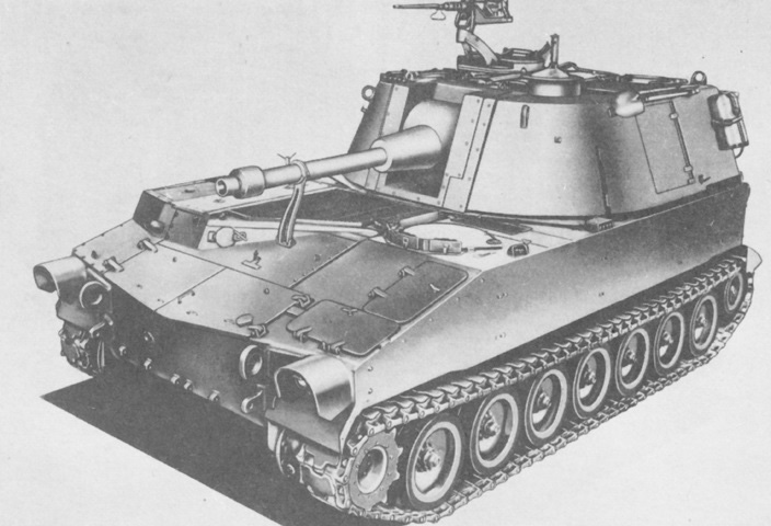
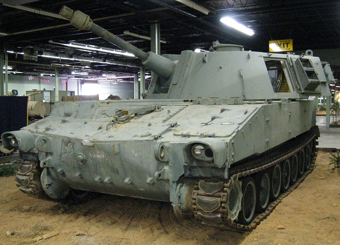
105mm Self-propelled Howitzer M108.
This M108 shows the large size of the vehicle that was built for a relatively small ordnance. The M108's hull and turret were shared with the more potently-armed M109, by which it would eventually be eclipsed. (Picture from TM 9-2350-217-20 C7.)
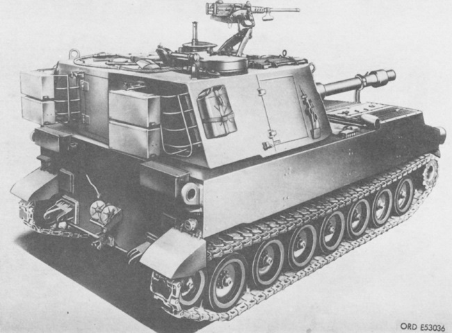
Stowage and the cab side and rear doors can be seen here. Unlike the M109, the M108 did not require rear spades for stability when firing. (Picture from TM 9-2350-217-20 C7.)
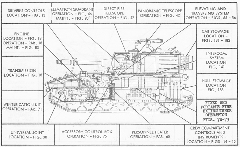
A cross-section of the vehicle is sketched. (Pictures from TM 9-2350-217-10 C3.)
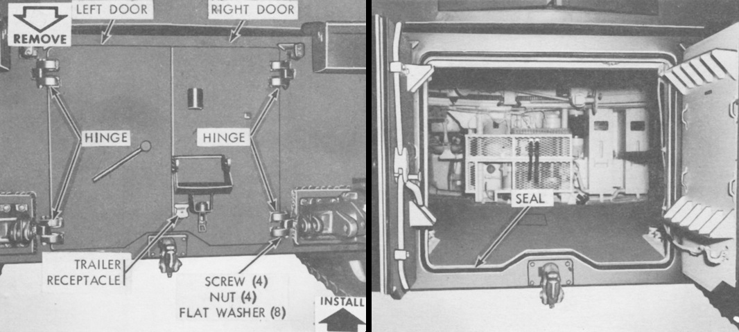
The hull rear had an entrance that could be sealed by one or two doors. The two-door version is shown here closed and opened. (Picture from TM 9-2350-217-20 C7.)
The single hull rear door is shown in this picture. (Picture from TM 9-2350-217-20 C7.)
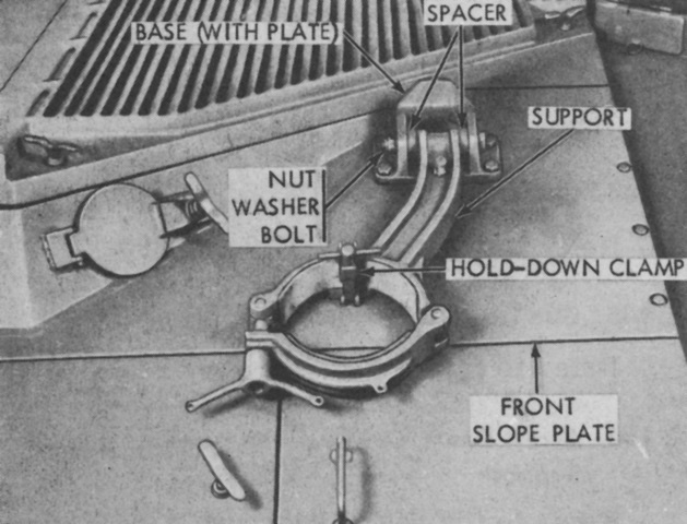
The travel lock is seen stowed on the hull front. The round cover left of the travel lock was for engine oil access. (Picture from TM 9-2350-217-20 C7.)
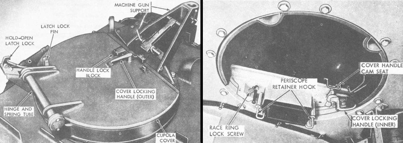
The exterior and interior of the commander's cupola is shown here. This cupola was mounted on all M108s and on M109s up to serial number 1122. (Picture from TM 9-2350-217-20 C7.)
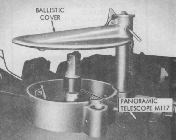
The panoramic telescope M117 is shown in position with its ballistic cover raised. The latch on top of the cover held it in place in the raised position, while the removable pin chained to the cover secured the cover in either the raised or lowered positions. (Picture from TM 9-2350-217-10 C3.)
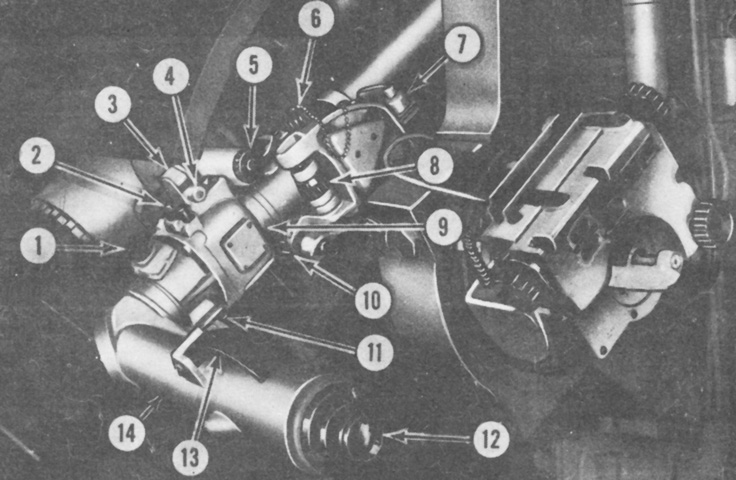
The telescope M118 was identical to the M118C found in the M109 except for the reticles. 1. Light control knob. 2. Reticle lever arm. 3. Level vial mirror. 4. Level vial. 5. Cant correction (crosslevel) knob. 6. King pin knob. 7. Mount electrical connector. 8. Elevation boresight knob. 9. Cant index. 10. Azimuth boresight knob. 11. Telescope electrical connector. 12. Eyepiece. 13. Arm release lever. 14. Eyepiece arm. (Picture from TM 9-2350-217-10 C3.)
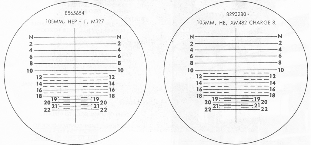
The M118 used the two reticle patterns drawn above, which were identical except that the geometric center of pattern 8565654 was slightly above the 12-mil horizontal line while the geometric center of 8293280 was slightly below the 16-mil horizontal line. The normal sighting line was denoted as "N," and the horizontal ranging lines were numbered in hundreds of meters. The vertical line extended 19.7 mils above and 74.25 mils below the normal sighting line, and the intersection of the vertical line and the normal sighting line was used for boresighting. The N through 10 horizontal lines were 30 mils wide, while lines 12 through 18 were 20 mils, lines 20 and 22 were 10 mils, and lines 19 and 21 were 5 mils. The dashed horizontal lines were made up of 2.5 mil-wide dashes and spaces. (Picture from TM 9-2350-217-10 C3.)
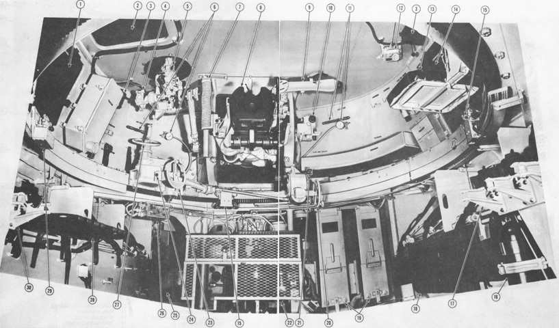
The cab and hull front are detailed in this composite image. 1. Cab left side door. 2. Gunner's escape hatch. 3. Intercom control box, C-375/VRC. 4. M145 panoramic telescope mount. 5. M117 panoramic telescope. 6. Cab race ring seal gage and air pump. 7. Equilibrator. 8. 105mm howitzer cannon and mount. 9. Direct fire telescope, M118. 10. Elevation quadrant, M15. 11. Gun shield seal gage and air pump. 12. Dome light. 13. Commander's seat. 14. Cab right side door. 15. Cab slip ring contact arm. 16. Portable fire extinguisher. 17. Hull ammunition rack (right). 18. Loader's (cannoneer's) seat (right). 19. Engine air cleaner. 20. Elevating handwheel. 21. Right firing switch. 22. Personnel heater. 23. Auxiliary elevating handwheel. 24. Left firing switch. 25. Driver's compartment. 26. Accessary control panel. 27. Traversing handwheel. 28. Loader's (cannoneer's) seat (left). 29. Traverse lock. 30. Hull ammunition rack (left). (Pictures from TM 9-2350-217-10 C3.)
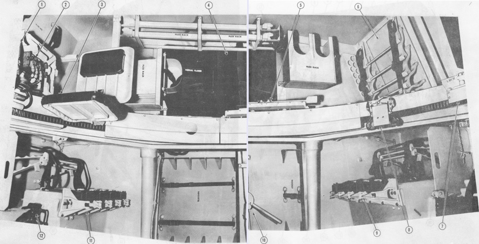
The cab and hull rear are shown in these pictures. 1. Interphone control C-980/U. 2. Intercommunication amplifier AM-65/GRC. 3. Commander's seat. 4. Cab rear door. 5. Fuzing and zoning tray. 6. Cab ammunition rack. 7. Traverse lock. 8. Cab slip ring contact arm. 9. Hull ammunition rack (left). 10. Hull rear door. 11. Hull ammunition rack (right). 12. Portable fire extinguisher. (Pictures from TM 9-2350-217-10 C3.)
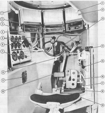
The driver's position is labeled in this picture, with his seat backrest lowered for clarity. When driving with his head out of the hatch, the steering wheel could be rotated about its hub so that it faced upwards. 1. Hatch control. 2. Dome light (hidden). 3. Auxiliary power receptacle. 4. Driver's periscope (3). 5. Master warning light. 6. Portable instrument panel. 7. Main instrument panel. 8. Brake lock. 9. Vehicle identification plate. 10. Brake pedal. 11. Hatch locking handle. 12. Fuel shut-off. 13. Steering wheel. 14. Transmission shift lever. 15. Throttle control lever. 16. Accelerator pedal. 17. Seat vertical control lever. 18. Headlight dimmer switch. 19. Driver's seat. (Picture from TM 9-2350-217-10 C3.)
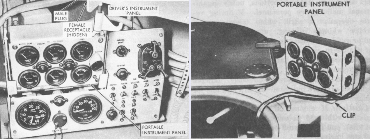
The driver was provided with a portable instrument panel so that if he was operating in the raised position, the portable panel could be detached from the main instrument panel and clipped to the hull roof, as seen on the right. (Pictures from TM 9-2350-217-20 C7 and TM 9-2350-217-10 C3.)
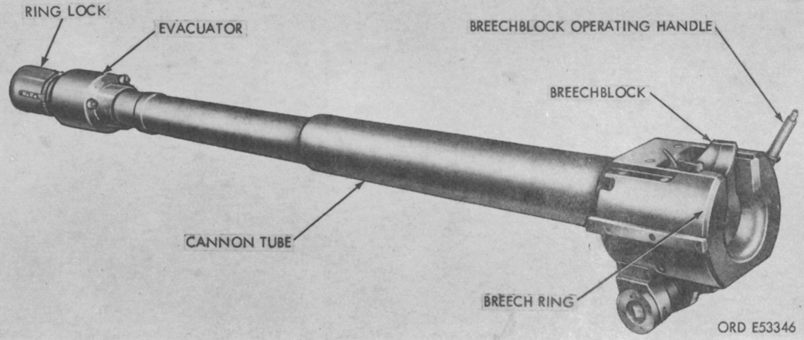
The 105mm howitzer cannon weighed 986lb (447kg) and used a manually-operated vertical sliding wedge breechblock. (Picture from TM 9-2350-217-20 C7.)
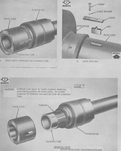
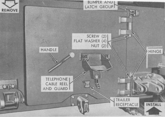
The howitzer ring lock and its securing hardware are shown in this picture. (Picture from TM 9-2350-217-20 C7.)
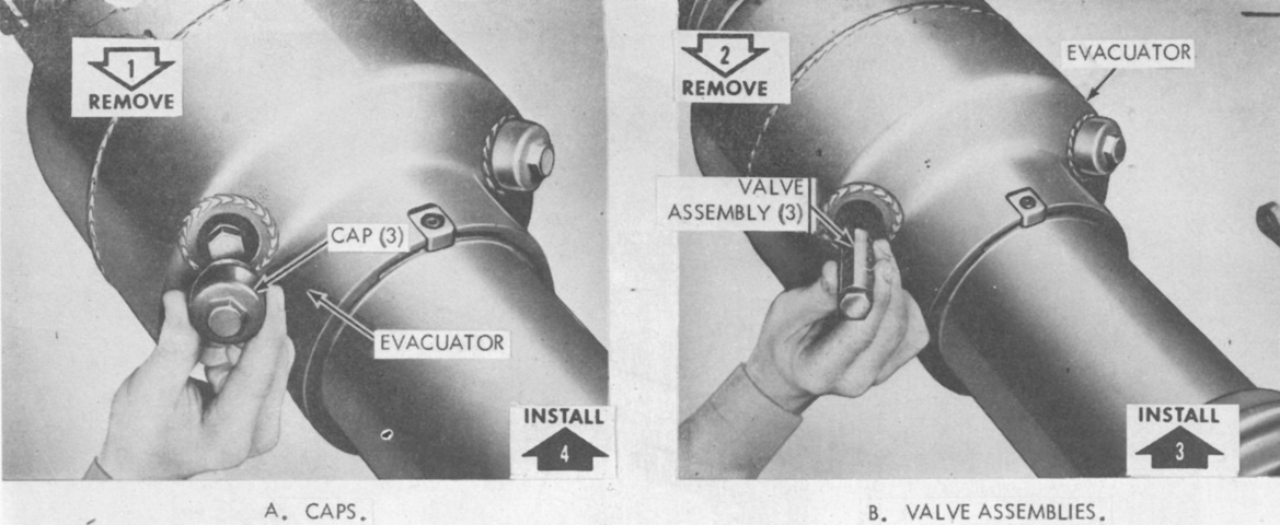
The bore evacuator valve assemblies were accessible from the rear of the chamber. (Picture from TM 9-2350-217-20 C7.)
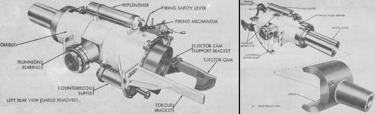
The howitzer mount is seen from the left rear and right front without the ordnance installed. Together, the howitzer and mount weighed 2,530lb (1,150kg). (Picture from TM 9-2350-217-20 C7.)
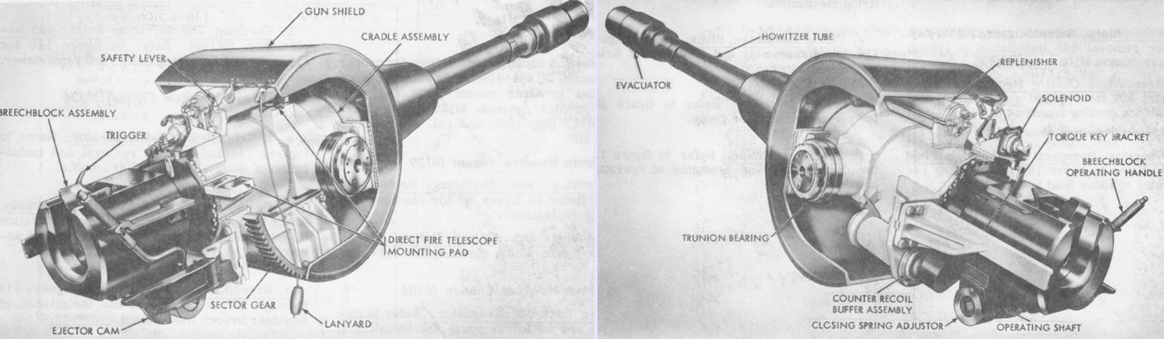
The assembled howitzer and mount are seen from the right and left rear. (Pictures from TM 9-2350-217-10 C3.)
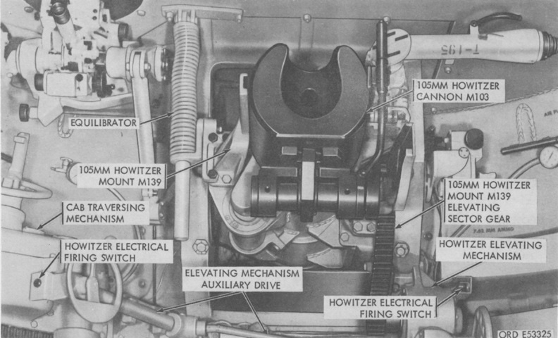
The breech of the howitzer can be seen in this view of the front of the turret. Traverse and elevation were both via manual handwheels. (Picture from TM 9-2350-217-20 C7.)
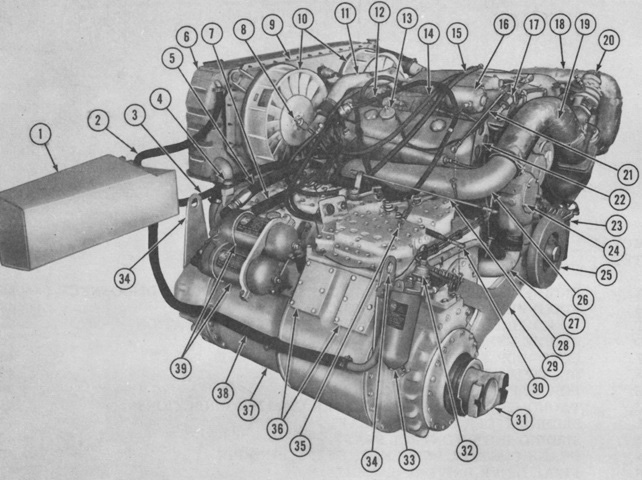
The powerplant is shown here from the left front. 1. Coolant surge tank. 2. Radiator-to-surge tank hose. 3. Bypass thermostat housing-to-surge tank hose. 4. Transmission breather. 5. Engine oil filter-to-oil cooler hose. 6. Coolant radiator. 7. Engine oil cooler-to-filter hose. 8. Engine oil level dipstick (indicator). 9. Radiator cooling fan shroud. 10. Radiator cooling fan. 11. Coolant crossover tube. 12. Generator-to-rectifier wiring harness. 13. Engine oil filler cap. 14. Tachometer drive shaft. 15. Speedometer drive shaft. 16. Engine air box heater fuel pump. 17. Air box heater fuel pump solenoid valve. 18. Engine exhaust bypass pipe. 19. Engine exhaust crossover pipe. 20. Turbocharger regulator assembly. 21. Engine governor throttle control rod. 22. Engine lifting eye. 23. Engine primary fuel filter. 24. Engine coolant pump. 25. Engine vibration (viscous) damper. 26. Engine right exhaust manifold. 27. Engine coolant inlet line. 28. Transmission throttle valve rod. 29. Engine and transmission support. 30. Transmission steer control rod. 31. Universal joint flange adapter. 32. Air cleaner dust exhauster motors switch. 33. Engine secondary fuel filter. 34. Power plant lifting eye (at transmission). 35. Transmission shift control rod. 36. Transmission inspection cover (brake adjustment). 37. Transmission. 38. Surge tank-to-coolant pump tube hose. 39. Engine oil filters. (Picture from TM 9-2350-217-20 C7.)
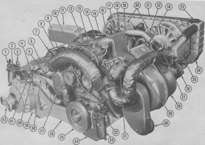
The powerplant is shown here from the left rear. 1. Air cleaner dust exhauster motors switch. 2. Engine secondary fuel filter. 3. Power plant lifting eye (at transmission). 4. Transmission steer control rod. 5. Transmission throttle valve rod. 6. Transmission shift control rod. 7. Engine governor throttle control rod. 8. Engine exhaust crossover pipe. 9. Engine oil filter. 10. Air box heater fuel pump solenoid. 11. Coolant surge tank. 12. Air box heater fuel pump. 13. Engine governor. 14. Engine lifting eye. 15. Speedometer drive shaft. 16. Tachometer drive shaft. 17. Engine blower inlet housing. 18. Coolant crossover tube drain plug. 19. Coolant crossover tube drain cock. 20. Radiator cooling fan. 21. Radiator cooling fan shroud. 22. Coolant crossover tube. 23. Radiator filler cap. 24. Radiator. 25. Inlet thermostat housing. 26. Engine exhaust outlet duct. 27. Engine coolant temperature transmitter. 28. Turbocharger. 29. Engine exhaust bypass pipe. 30. Engine turbocharger inlet duct. 31. Turbocharger regulator assembly. 32. Fuel supply quick disconnect. 33. Engine primary fuel filter. 34. Engine oil pan. 35. Engine vibration (viscous) damper. 36. Engine and transmission support. 37. Engine coolant pump. 38. Coolant pump-to-surge tank tube. 39. Transmission. 40. Transmission right brake apply shaft lever. 41. Transmission left brake apply shaft lever. 42. Universal joint flange adapter. (Picture from TM 9-2350-217-20 C7.)
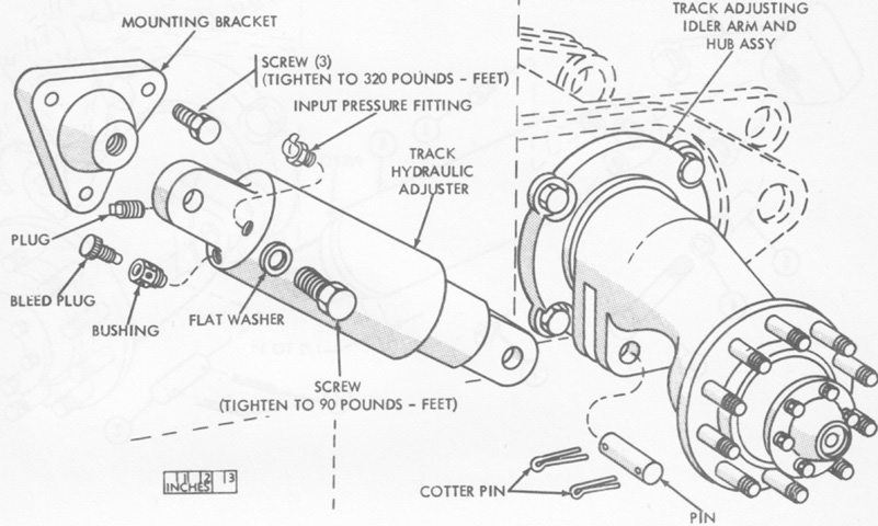
An exploded view of the idler adjustment mechanism is provided in this sketch. This design appeared on all M108s as well as on M109s up to serial number 1122. In order to increase track tension, lubricant was added via a grease gun to the input pressure fitting. To decrease tension, lubricant was removed from the adjuster via the bleed plug. (Picture from TM 9-2350-217-20 C7.)
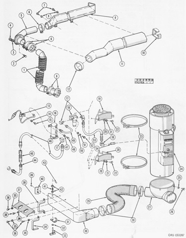
The personnel heater system is diagrammed here. 1. Flexible exhaust tube. 2. Exhaust adapter tube attaching screw (3). 3. Exhaust adapter tube lock washer (3). 4. Exhaust adapter tube nut (3). 5. Exhaust adapter tube. 6. Tube clamp. 7. Exhaust crossover tube attaching screw. 8. Exhaust crossover tube attaching lock washer. 9. Exhaust crossover tube. 10. Exhaust tube insulation band (2). 11. Exhaust tube insulation. 12. Insulation band. 13. Connector assy (circuit no. 402A). 14. Connector attaching lock washer. 15. Connector attaching screw. 16. Electric fuel pump. 17. Elbow. 18. Fuel filter. 19. Heater mounting saddle. 20. Saddle mounting flat washer (4). 21. Saddle mounting lock washer (4). 22. Saddle mounting screw (4). 23. Heater mounting clamp. 24. Personnel heater. 25. Lower duct attaching lock washer (4). 26. Lower duct attaching screw (4). 27. Lower duct. 28. Outlet hose clamp. 29. Outlet hose. 30. Outlet duct. 31. Outlet duct valve index plate. 32. Outlet duct valve handle flat washer. 33. Outlet duct valve handle. 34. Outlet duct bracket. 35. Outlet duct attaching flat washer. 36. Outlet duct attaching screw. 37. Outlet duct guard. 38. Outlet duct mounting clamp. 39. Outlet duct valve pin (2). 40. Outlet duct valve. 41. Outlet duct valve spring. 42. Outlet duct valve spring flat washer. 43. Outlet duct valve handle retaining pin. 44. Bulkhead-to-coupler fuel hose. 45. Fuel coupler (quick disconnect). 46. Coupler-to-electric fuel pump hose. 47. Electric fuel pump attaching lock washer (2). 48. Electric fuel pump attaching screw (2). 49. Fuel pump-to-filter tube. 50. Fuel filter attaching flat washer (2). 51. Fuel filter attaching lock washer (2). 52. Fuel filter attaching screw (2). 53. Fuel filter-to-heater hose. 54. Personnel heater fuel nipple. (Picture from TM 9-2350-217-20 C7.)
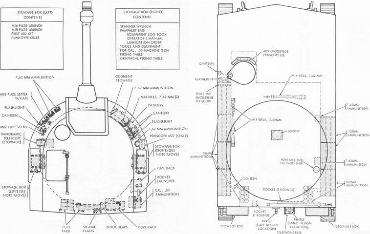
Internal stowage, including ammunition, is detailed in these sketches. (Pictures from TM 9-2350-217-10 C3.)
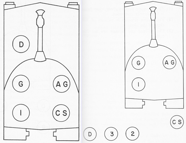
The howitzer section is shown mounted in the left image and prepared for action on the right. Two more cannoneers were part of the section as seen on the right, but traveled in a separate vehicle. (Picture from FM 6-79 105-mm Howitzer M108, Self-propelled.)
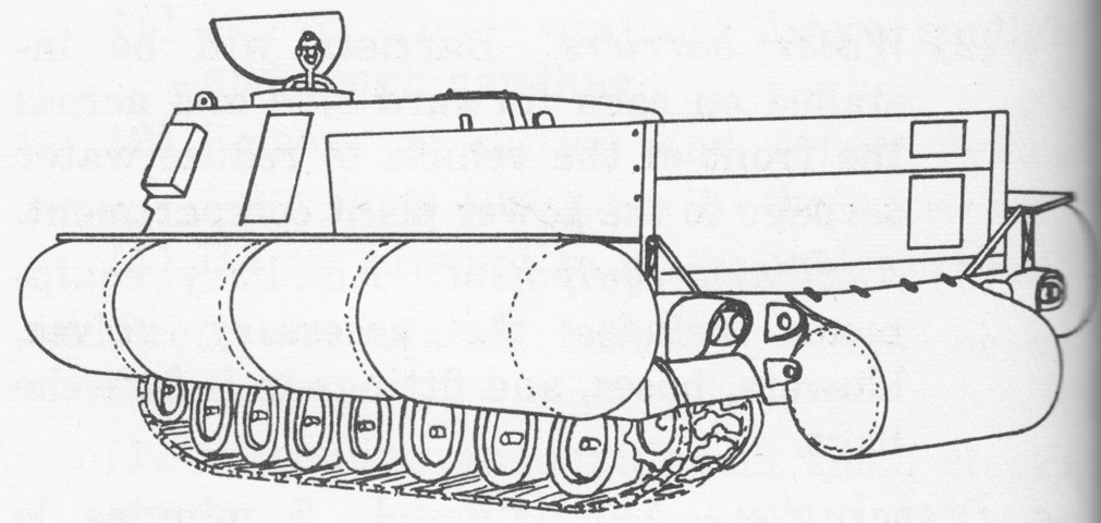
This sketch shows the howitzer with the flotation device installed. Four neoprene-impregnated nylon bags were attached to each side and one to the bow. Water barriers were erected on the hull; and a turboblower, air valves, and hosing and fittings were used for bag inflation. (Picture from FM 6-79 105-mm Howitzer M108, Self-propelled.)
The transmission access plates on the hull front top are visible, with their hinges just inboard of the lifting eyes. The howitzer travel lock is folded down. The doors on the hull's left side above the track were for access to the batteries. The driver's shuttered periscopes are visible on the left side of the hull, with the engine across from him on the right side of the vehicle. The cab left side door is open, allowing us a glimpse into the turret, and the commander's cupola can be seen on the far side of the turret roof.
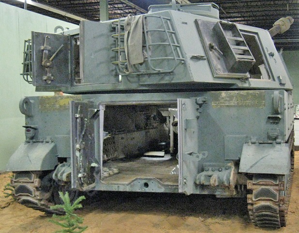
The hull and cab rear doors as well as the cab right side door are also open on this vehicle
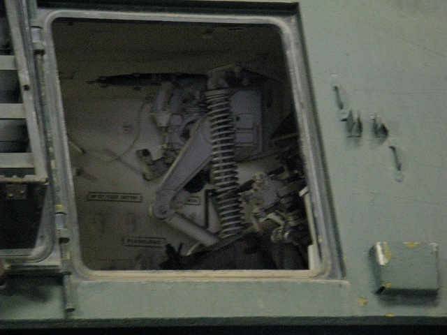
This view is looking into the open cab right side door, towards the left-hand turret interior. The large spring was part of the howitzer equilibrator mechanism, and the mount for the panoramic telescope M17 is beyond the spring.
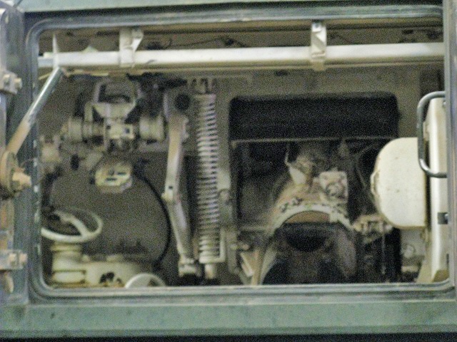
This picture was taken through the open cab rear doors. The breech of the 105mm howitzer is on the far end, and the commander's seat back is visible directly in front of the open doors. The horizontal handwheel below the panoramic telescope mount is for traverse, and the top portion of the auxiliary elevating handwheel can be seen at the bottom of the image. The bar going across the top of the opening above the commander's seat was part of the fuze rack.
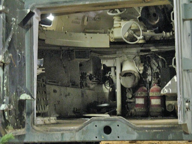
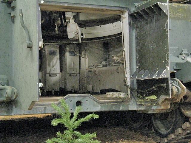
Looking through the hull rear doors, the traversing and auxiliary elevating handwheels are again visible, providing a reference to the above image. The turret traverse lock mechanism is directly below the light coming in through the open cab left side door, and the opening to the driver's compartment can be seen towards the front left corner of the fighting compartment. Parts of the left side hull ammunition rack can be glimpsed towards the rear of the vehicle, and just beyond this is the folded-down, woven seat for one of the cannoneers.
The opposite side of the fighting compartment is illustrated here. The elevating handwheel is visible at the front of the fighting compartment, and the engine air cleaners are the two locker-like structures directly below it. Parts of the right side hull ammunition rack can again be seen, but another seat for the other cannoneer appears to be missing.
