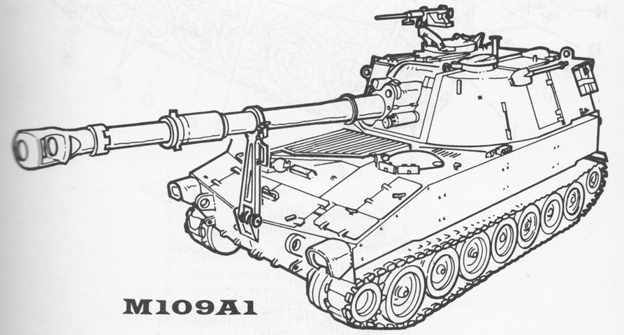
155mm Self-propelled Howitzer M109.
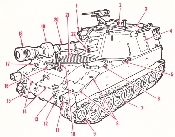
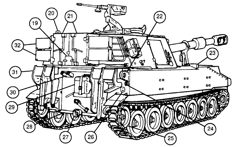
The M109 used the same turret and hull as the 105mm SPH M108. 1. Cab front lifting eye (2). 2. Ballistic cover. 3. Gunner's escape hatch. 4. Cab left side door. 5. Fixed fire extinguisher actuating handle. 6. Driver's hatch. 7. Road wheel (14). 8. Battery access doors. 9. Drive sprocket (2). 10. Howitzer travel lock. 11. Headlight (2). 12. Front towing eye (2). 13. Front lifting eye (2). 14. Transmission access doors. 15. Final drive filler plug (2). 16. Engine oil access door. 17. Bilge pump outlet. 18. Muzzle brake. 19. Evacuator. 20. Howitzer cannon M126/M126A1. 21. Engine grill [sic] cover. 22. Recuperator. (Picture from TM 9-2350-217-10N.)
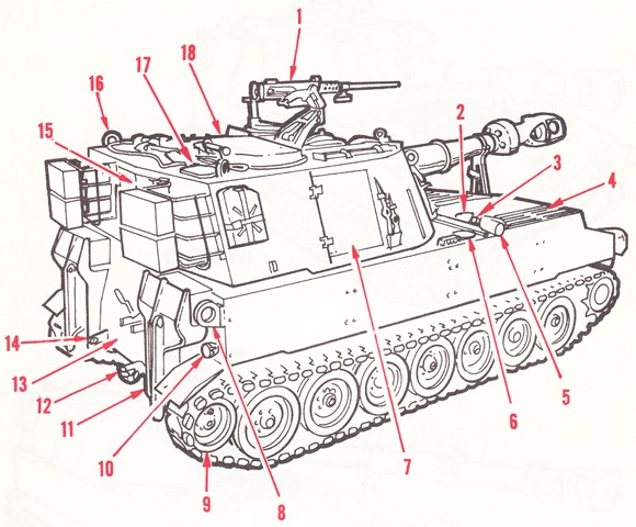
1. Cal .50 machine gun. 2. Radiator cap access cover. 3. Personnel heater exhaust. 4. Exhaust grille. 5. Exhaust outlet. 6. Fuel access cover. 7. Cab right side door. 8. Rear lifting eye (2). 9. Idler wheel (2). 10. Taillight (2). 11. Spade (2). 12. Tow pintle. 13. Crew compartment access door. 14. Rear towing eye (2). 15. Rear cab doors. 16. Cab rear lifting eye (2). 17. Main accumulator cab access plate. 18. Commander's cupola. (Picture from TM 9-2350-217-10N.)
The interior layout is visualized in this cross-sectional sketch. (Picture from TM 9-2350-217-10 C3.)
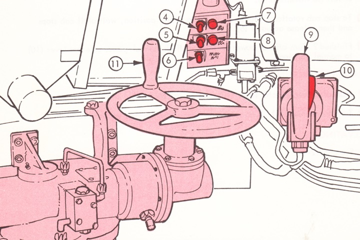
The driver's station is illustrated in this drawing. The steering wheel could be changed to an upward orientation when the driver was driving in the raised position. (Picture from TM 9-2350-217-10N.)
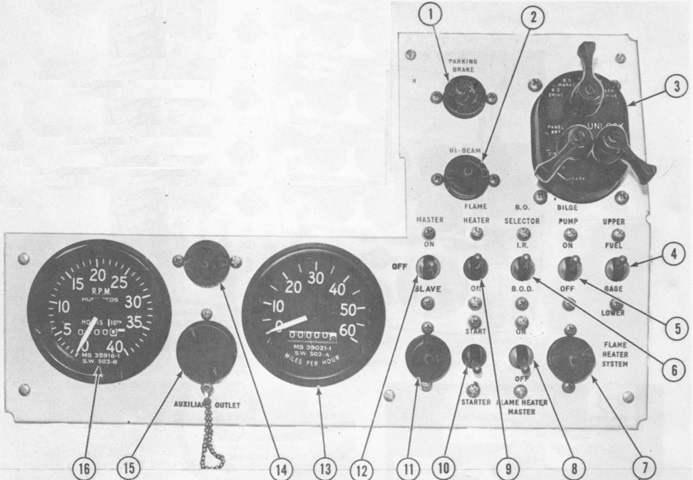
The driver's main instrument panel is labeled here. 1. Parking brake indicator light. 2. Hi-beam indicator light. 3. Light switch assembly. 4. Fuel tank gage selector switch. 5. Bilge pump switch. 6. I.R./B.O.D. [infrared/blackout drive light] selector switch. 7. Flame heater warning light. 8. Flame heater master switch. 9. Flame heater switch. 10. Starter switch. 11. Master switch warning light. 12. Master switch (all M108, M109 through serial number 1122); master/slave switch (M109 after serial number 1122). 13. Speedometer. 14. Panel light. 15. Auxiliary power outlet. 16. Tachometer. (Picture from TM 9-2350-217-20 C7.)
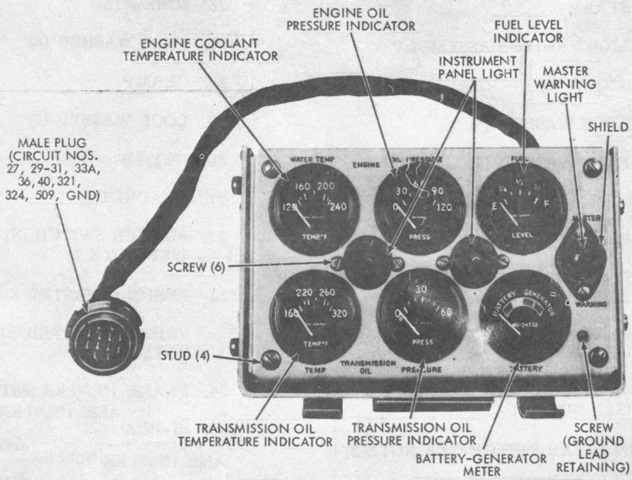
The driver was provided with a portable instrument panel that could be stowed on the main instrument panel or clipped to the hull roof when driving in the raised position. (Picture from TM 9-2350-217-20 C7.)
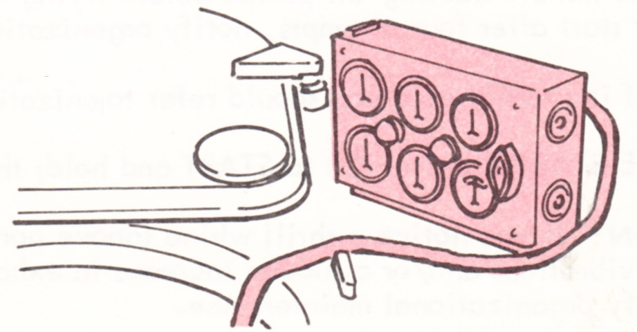
The portable instrument panel is depicted here in use on the hull roof. The driver's hatch and door are to the left. (Picture from TM 9-2350-217-10N.)
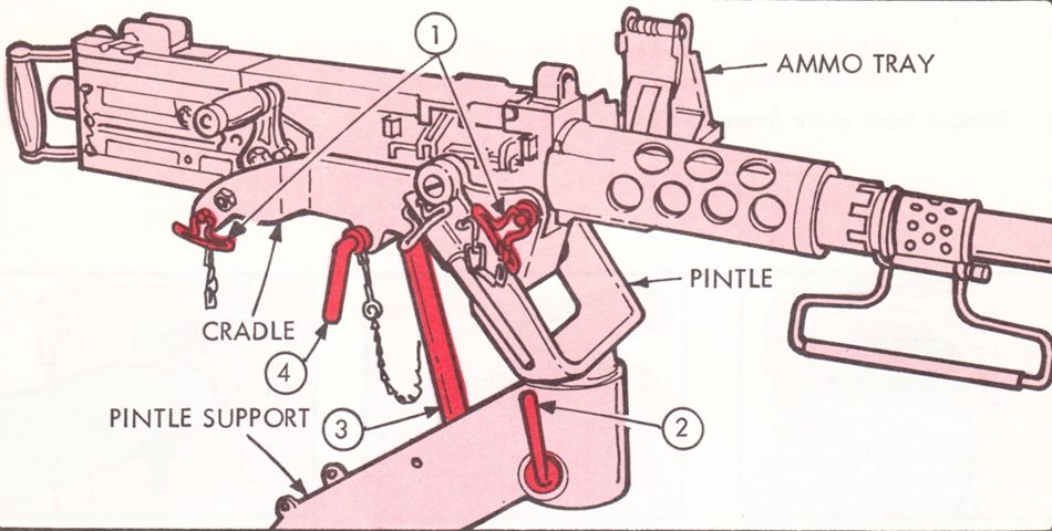
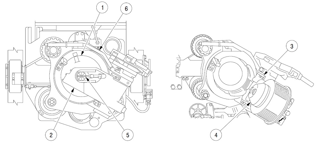
The cupola mount for the commander's machine gun is drawn in this picture. To install the machine gun pintle into the cradle, lock handle (2) was pulled downwards, and the machine gun was held with locking pins (1). Travel lock (3) was held with travel lock pin (4). (Picture from TM 9-2350-217-10N.)
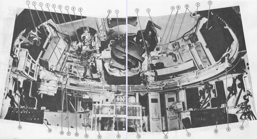
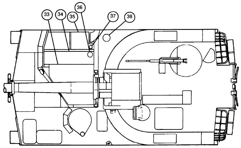
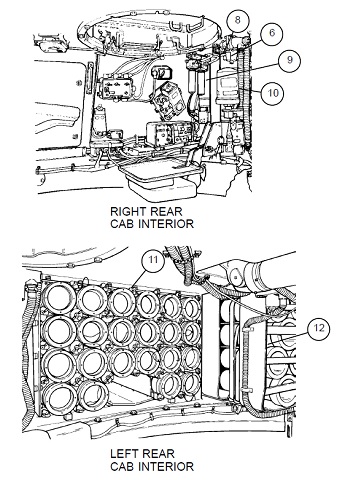
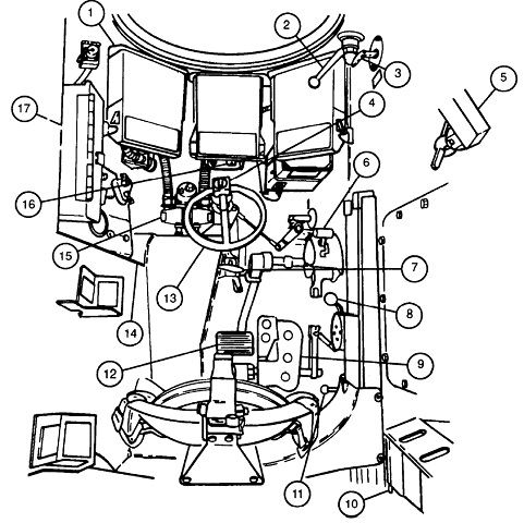
This composite image showcases the front of the hull and cab. 1. Cab left side door. 2. Gunner's selector assembly. 3. Manual traversing handwheel. 4. Gunner's control. 5. Intercom control box C-375/VRC. 6. Equilibrator system. 7. M145 panoramic telescope mount. 8. Gunner's escape hatch. 9. M117 panoramic telescope. 10. Cab race ring seal gage and air pump. 11. 155mm howitzer cannon and mount. 12. Elevation control assembly. 13. Direct fire telescope M118C. 14. Elevation quadrant M15. 15. Gun shield seal gage and air pump. 16. Dome light. 17. Cab right side door. 18. Portable fire extinguisher. 19. Cab slip ring contact arm. 20. Loader's (cannoneer's) seat (right). 21. Ammunition rack. 22. Engine air cleaner. 23. Personnel heater. 24. Traverse lock. 25. Driver's compartment. 26. Accessary control panel. 27. Speed selector lever. 28. Manual-power selector lever. 29. Loader's (cannoneer's) seat (left). (Pictures from TM 9-2350-217-10 C3.)
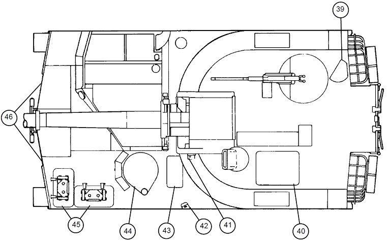
The rear of the hull and cab interior are labeled here. 1. Power relay box. 2. Commander's seat. 3. Accumulator. 4. Power pack sight gage. 5. Power pack. 6. Intercommunication amplifier AM-65/GRC. 7. Rammer valve. 8. Interphone control, C-980/U. 9. Rammer. 10. Cab rear door. 11. Cab ammunition rack. 12. Cab slip ring contact arm. 13. Hull ammunition rack. 14. Hull rear door. (Pictures from TM 9-2350-217-10 C3.)
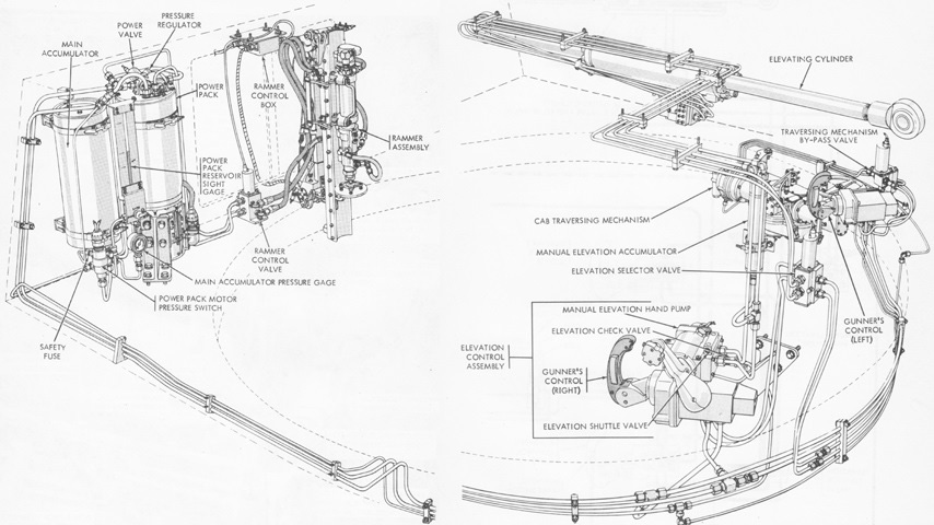
Two images have been combined to provide an overview of the cab hydraulic system. (Picture from TM 9-2350-217-20 C7.)
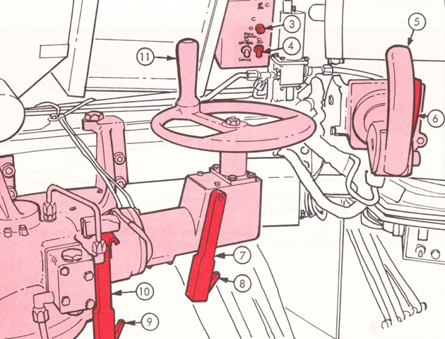
The traverse controls are highlighted here. 3. Cab power indicator light. 4. Cab power switch. 5. Gunner's control handle. 6. Actuator. 7. Speed selector lever. 8. Speed selector lever-locking trigger. 9. Manual-power lever-locking trigger. 10. Manual-power lever. 11. Traversing handwheel. (Picture from TM 9-2350-217-10N.)
The manual elevation hand pump knob (14) was on the number 1 man's control handle (13) to the right of the ordnance. (Picture from TM 9-2350-217-10N.)
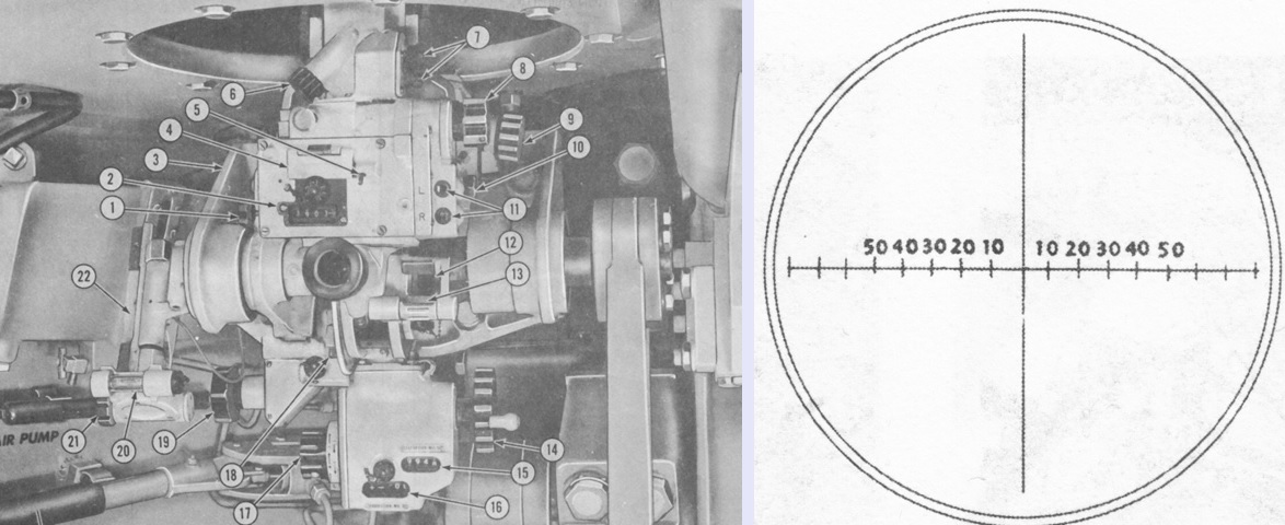
The panoramic telescope M117 and mount M145 are labeled in this image, with the reticle pattern sketched on the right. The M117 was a 4x device with a 10° field of view. It was used to set the howitzer in azimuth during indirect fire and when using the two-man, two-sight system for direct fire. The horizontal line in the reticle was marked in tens of mils; later variants of the M117 had the horizontal line labeled out to 80 mils. 1. Reset knob. 2. Reset counter (3200-mil). 3. Lamp toggle switch (hidden). 4. Azimuth counter (6400-mil). 5. Azimuth counter door release. 6. Elevation knob. 7. Rheostat knobs. 8. Azimuth knob. 9. Crosslevel knob. 10. Gunner's aid knob. 11. Gunner's aid counters. 12. Pitch level vial. 13. Crosslevel level vial. 14. Elevation handwheel. 15. Elevation counter. 16. Correction counter. 17. Elevation correction knob. 18. Elevation level vial. 19. Pitch knob. 20. Quadrant crosslevel vial. 21. Quadrant level knob. 22. Quadrant seat. (Picture from TM 9-2350-217-10 C3.)
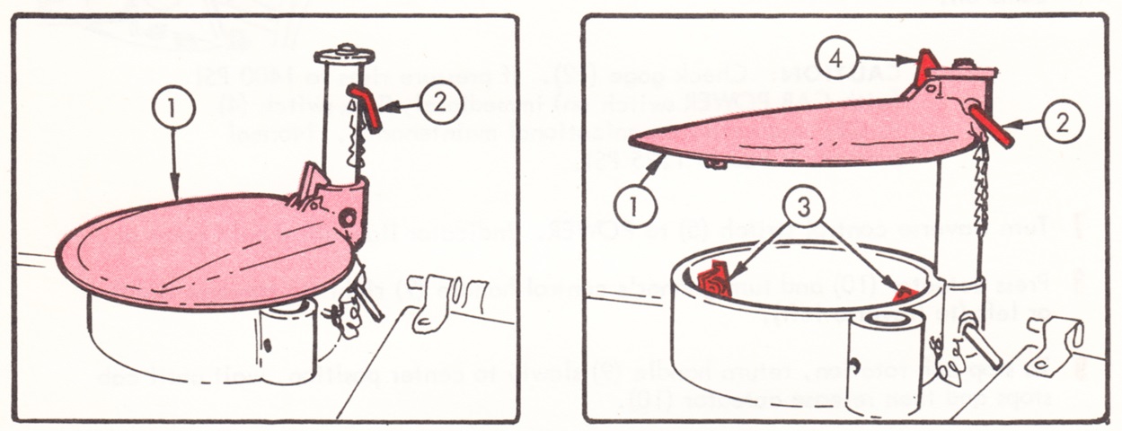
To raise the panoramic telescope's ballistic cover (1), pin (2) needed to be pulled and cover latches (3) needed to be released. Then the cover was raised and secured by latch (4) and the reinstallation of pin (2). (Picture from TM 9-2350-217-10N.)
The telescope M118C or M118CA1 in mount M146 was used to lay the howitzer in elevation when using the 2-man, 2-sight system for direct fire. The M118C was a 4x device with a 10° field of view. It was 38" (97cm) long, 14" (36cm) wide including the eyepiece arm, 7½" (19cm) tall, and weighed 44lb (20kg). It could correct for cant up to ±5°. 1. Light control knob. 2. Reticle detent knob. 3. Level vial mirror. 4. Level vial. 5. Cant correction (cross level [sic]) knob. 6. King pin knob. 7. Elevation boresight scale. 8. Elevation boresight knob. 9. Eyepiece. 10. Release lever. 11. Eyepiece arm. 12. Azimuth boresight knob. 13. Azimuth boresight scale. (Picture from TM 9-2350-217-10N.)
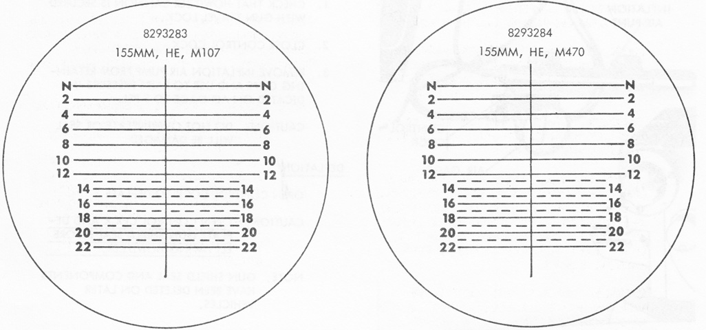
The two reticles used in the M118C are drawn here. The patterns were identical except that the geometric center of pattern 8293283 was slightly above the 12-mil horizontal line while the geometric center of 8293284 was slightly below the 16-mil horizontal line. The normal sighting line was denoted as "N," and the horizontal ranging lines were numbered in hundreds of meters. The vertical line extended 9.8 mils above and 49.2 mils below the normal sighting line, and the intersection of the vertical line and the normal sighting line was used for boresighting. The N through 12 horizontal lines were 30 mils wide, while lines 13 through 22 were 20 mils. The dashed horizontal lines were made up of 2 mil-wide dashes and spaces. (Picture from TM 9-2350-217-10 C3.)
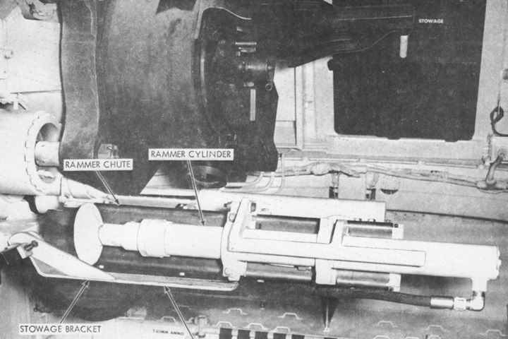
The weapon mounted projectile rammer is shown here in the stowed position. (Picture from TM 9-2350-217-20 C7.)
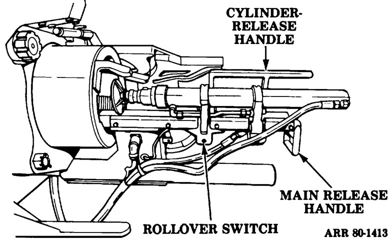
The rammer is sketched in the ram position. The cylinder release handle was used to rotate the rammer cylinder from the load position into the ram position, where it would then latch the rammer into place. Lifting the handle released the latch, allowing the rammer cylinder to be rotated back into the load position. The main release handle unlatched the rammer from the stowed position, pulled the rammer rearward on the rammer support shaft, and assisted in lifting the rammer into the ram position. The rollover switch was activated when the rammer cylinder was rotated to the load position. (Picture from TM 9-3305 Principles of Artillery Weapons.)
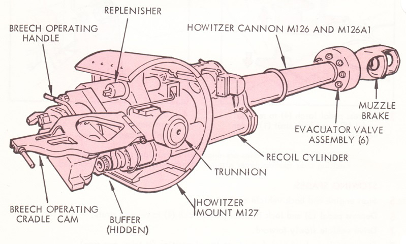
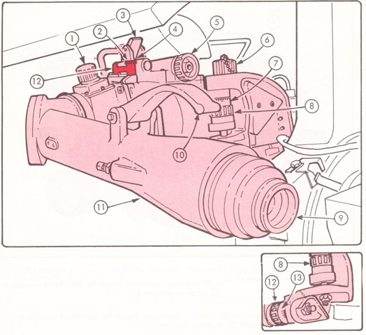
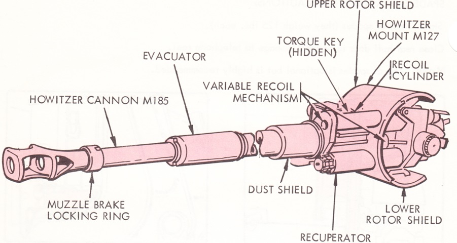
The 155mm howitzer M126 utilized tube 8768691 while the M126A1 was fitted with tube 11576737. The former tube weighed 2,006lb (909.9kg) and the latter 2,069lb (938.5kg), yielding a weight of 3,137lb (1,423kg) for the M126 and 3,200lb (1,450kg) for the M126A1. The M126 tube's estimated accuracy life was 15,000 equivalent full charge rounds. The mount M127 weighed 3,130lb (1,420kg) with 6 gallons (23L) of oil in the recoil mechanism. Normal recoil at high elevation was 24" (61cm), and maximum at low elevation was 36" (91cm). (Picture from TM 9-2350-217-10N.)
The howitzer mount M127 is shown from the left rear and right front. (Picture from TM 9-2350-217-20 C7.)
The fluid level in the equilibrator reservoir was to be even with mark (6) when the system was pressurized. (Picture from TM 9-2350-217-10N.)
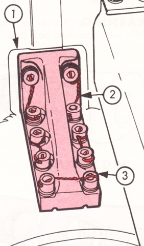
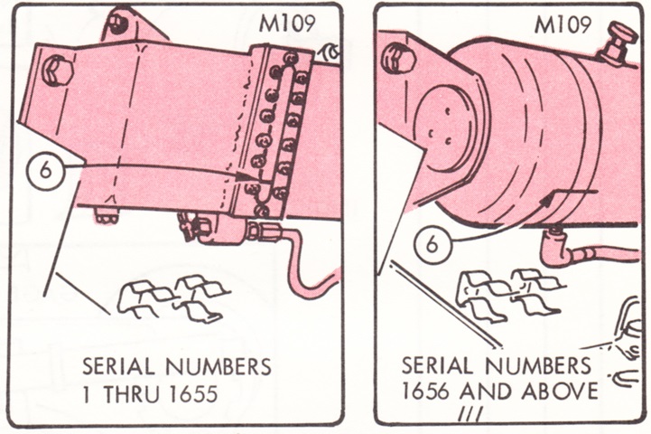
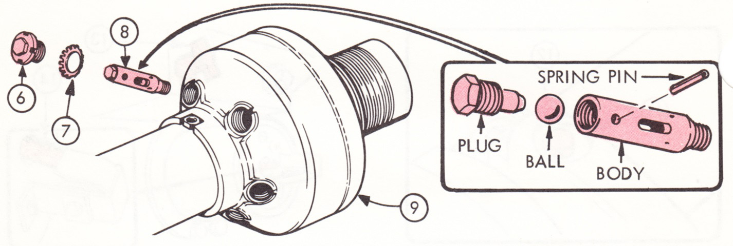
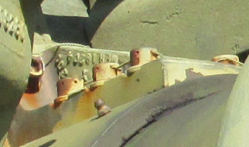
The torque key (1) at the base of the mount was held with ten 5⁄16" (.7938cm) allen screws (3) and washers and secured with locking wire (2). It was to be removed and checked for wear after every 1,500 rounds fired. (Picture from TM 9-2350-217-10N.)
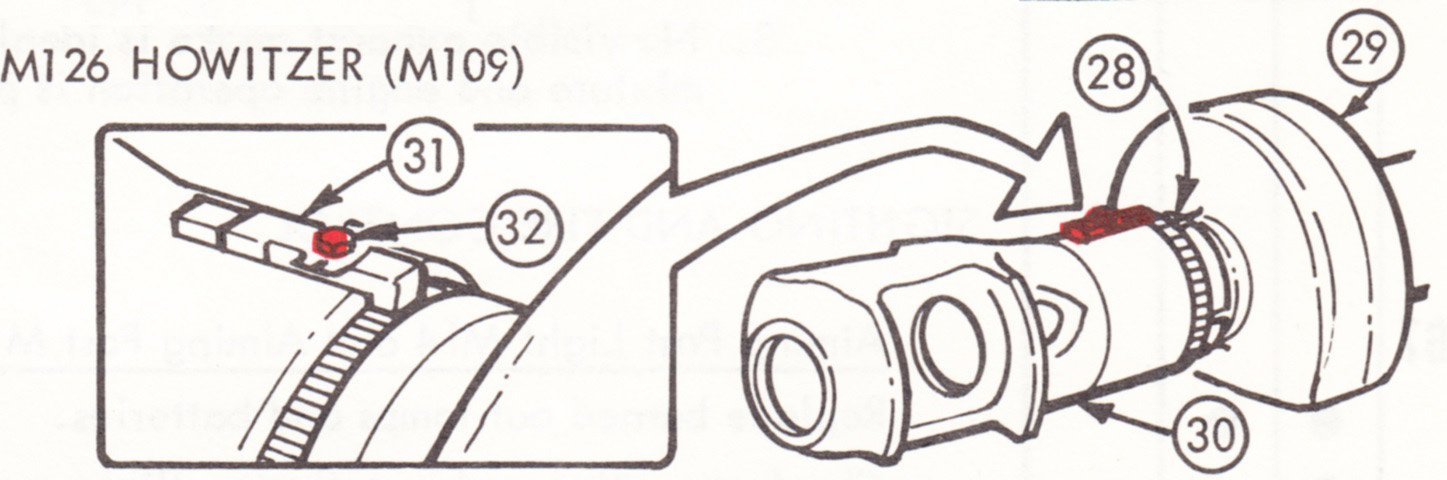
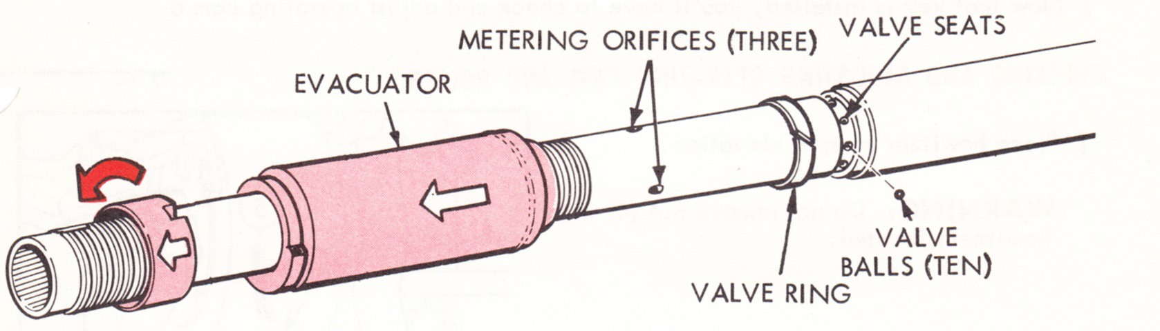
The muzzle brake (30) weighed 350lb (160kg), and was to be checked for cracks after every 250 rounds fired. If a crack was found that was over 1" (2.5cm) long, the brake was considered unserviceable. The locking ring (28) was to be flush with the rear of the muzzle brake, and the evacuator key (31) was held by lock screw (32). (Picture from TM 9-2350-217-10N.)
After every 300 rounds fired, or monthly, the bore evacautor (9) was to be removed, cleaned, and the inside coated with a light layer of GAA grease. The valve assemblies (8) could be obtained after removing the caps (6) and lock washers (7). (Picture from TM 9-2350-217-10N.)
The functioning of the howitzer travel lock is illustrated here. (Picture from TM 9-2350-217-10N.)
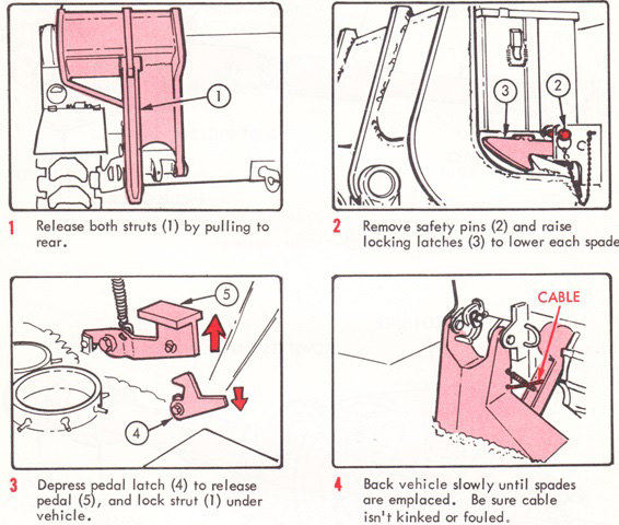
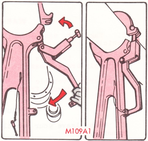
The emplacement procedure for the spades is outlined in this series of sketches. The spades each weighed 125lb (56.7kg), and therefore took two men to restow on the hull. (Picture from TM 9-2350-217-10N.)
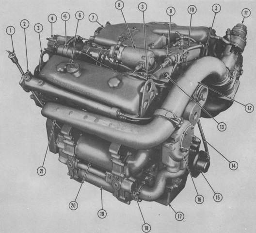
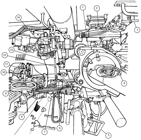
The engine is shown here from the right front. 1. Engine oil dipstick (indicator). 2. Coolant manifold--right. 3. Engine lifting eye. 4. Generator (alternator) mounting housing. 5. Engine flame heater coil. 6. Engine crankcase oil filler cap. 7. Engine blower inlet housing. 8. Flame heater fuel pump. 9. Flame heater fuel pump solenoid. 10. Engine governor. 11. Engine turbocharger regulator assembly. 12. Engine exhaust crossover pipe. 13. Flame heater electrical receptacle. 14. Fuel filter-to-engine fuel pump hose. 15. Engine vibration (viscous) damper adapter. 16. Engine coolant pump. 17. Engine oil pan. 18. Engine oil cooler inlet. 19. Engine oil cooler. 20. Transmission oil cooler. 21. Engine right exhaust manifold. (Picture from TM 9-2350-217-20 C7.)
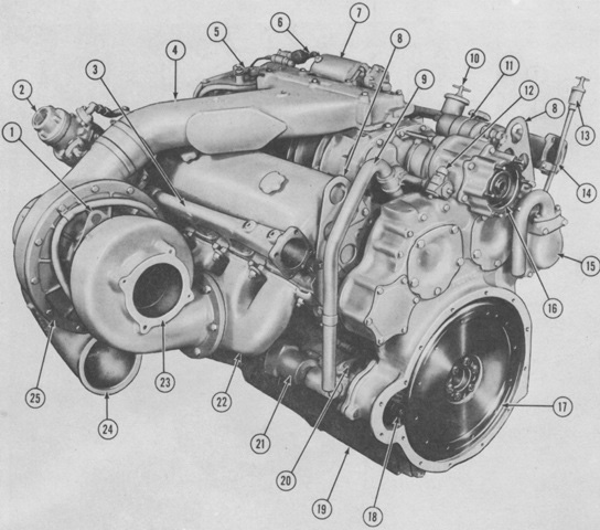
The left rear of the engine is labeled. 1. Turbocharger lifting eye. 2. Engine turbocharger regulator assembly. 3. Coolant manifold--left. 4. Engine blower inlet housing. 5. Engine governor. 6. Flame heater fuel pump solenoid. 7. Flame heater fuel pump. 8. Engine lifting eye. 9. Crankcase breather. 10. Engine oil filler cap. 11. Engine flame heater coil. 12. Tachometer drive adapter. 13. Engine oil dipstick (indicator). 14. Coolant manifold--right. 15. Engine gear train breather. 16. Generator (alternator) mounting housing. 17. Engine flywheel. 18. Starter motor drive. 19. Engine oil pan. 20. Engine starter motor. 21. Starter motor solenoid. 22. Engine left exhaust manifold. 23. Turbocharger exhaust outlet. 24. Turbocharger air inlet housing. 25. Turbocharger. (Picture from TM 9-2350-217-20 C7.)
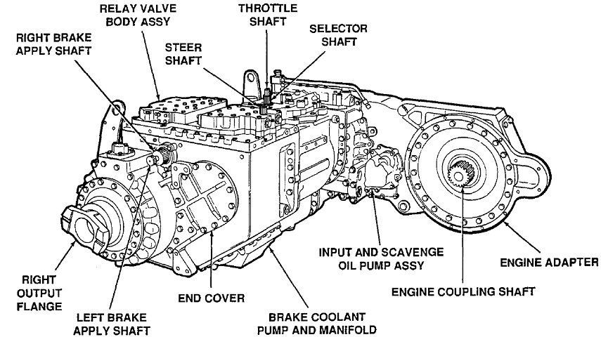
The XTG-411-2A or -4 power train is shown here. The XTG-411-2A's overall dry weight was 3,745lb (1,699kg), its maximum input torque was 880 lb-ft, maximum net input horsepower was 360, and the maximum input speed was 2300rpm. The later XTG-411-4 weighed 3,805lb (1,726kg), and its maximum input torque, input speed, and net input horsepower were 1200 lb-ft, 2500rpm, and 575, respectively. The -2A's maximum torque converter ratio at stall was 3.3:1, compared to 3.2:1 for the -4. (Picture from TM 9-2520-234-35.)
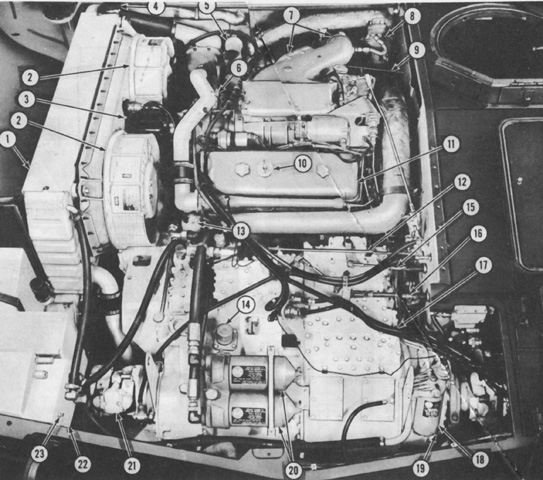
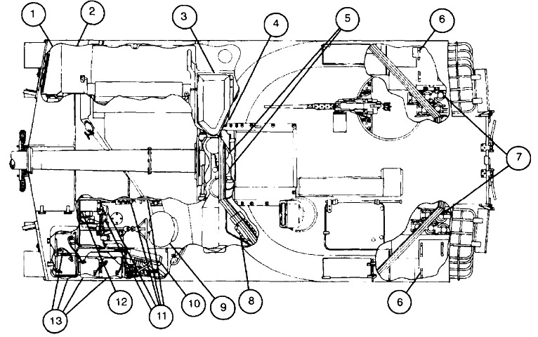
More detailed labeling of the left front of the transmission and transfer assemblies and accessories is provided in this image. 1. Engine mounting flange adapter. 2. Engine oil cooler-to-filter hose. 3. Transmission-to-oil cooler hose. 4. Transmission throttle valve rod. 5. Steering control rod. 6. Transmission steer shaft rod lever. 7. Transmission shaft control linkage. 8. Air cleaner dust exhauster motor switch. 9. Transmission lifting eye. 10. Low oil pressure switch. 11. Oil pressure transmitter. 12. Transmission assembly. 13. Oil temperature transmitter. 14. Oil cooler-to-transmission hose elbow. 15. High oil temperature switch. 16. Engine oil filter. 17. Oil cooler-to-oil filter hose elbow. 18. Transmission breather. 19. Speedometer drive. 20. Surge tank-to-coolant pump tube hose. 21. Universal joint flange adapter. 22. Radiator mounting bracket. 23. Input transfer housing. 24. Radiator cooling fan drive. 25. Radiator mounting bracket. (Picture from TM 9-2350-217-20 C7.)
More detailed labeling of the right front of the transmission and transfer assemblies and accessories is provided in this image. 1. Universal joint flange adapter. 2. Engine secondary fuel filter. 3. Air cleaner dust exhauster motor switch. 4. Transmission lifting eye. 5. Left brake apply lever. 6. Right brake apply lever. 7. Transmission steer control rod. 8. Transmission throttle valve rod. 9. Engine oil filters. 10. Oil cooler-to-oil filter hose elbow. 11. Transmission breather. 12. Oil pressure transmitter. 13. Oil cooler-to-transmission hose elbow. 14. Low oil pressure switch. 15. Radiator mounting bracket. 16. Input transfer housing. 17. Radiator mounting bracket. 18. Engine mounting flange adapter. 19. Engine oil cooler-to-filter hose. 20. Transmission-to-oil cooler hose. 21. Surge tank-to-coolant pump tube hose. (Picture from TM 9-2350-217-20 C7.)
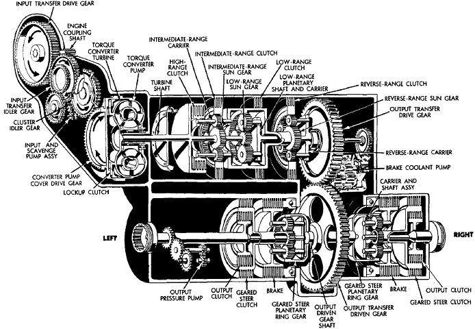
A schematic of the gearing and clutches in the transmission is provided here. (Picture from TM 9-2520-234-35.)
The powerplant is shown here installed in the hull. 1. Radiator. 2. Radiator cooling fan. 3. Generator (alternator). 4. Radiator filler cap. 5. Fixed fire extinguisher discharge horn. 6. Engine coolant drain cock. 7. Turbo-charger air outlet. 8. Turbo-charger regulator assy. 9. Fuel shut-off cable. 10. Engine oil filler cap. 11. General Motors 8V71T diesel engine. 12. Transmission throttle valve rod. 13. Engine oil dipstick. 14. Transmission filler cap and dipstick. 15. Transmission shift control knob. 16. Transmission steer control rod. 17. Allison Model XTG-411-2A transmission. 18. Engine secondary fuel filter. 19. Filter drain cock. 20. Engine oil filter. 21. Universal joint. 22. Coolant surge tank. 23. Coolant surge tank drain cock. (Picture from TM 9-2350-217-10 C3.)
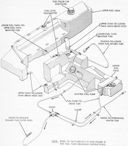
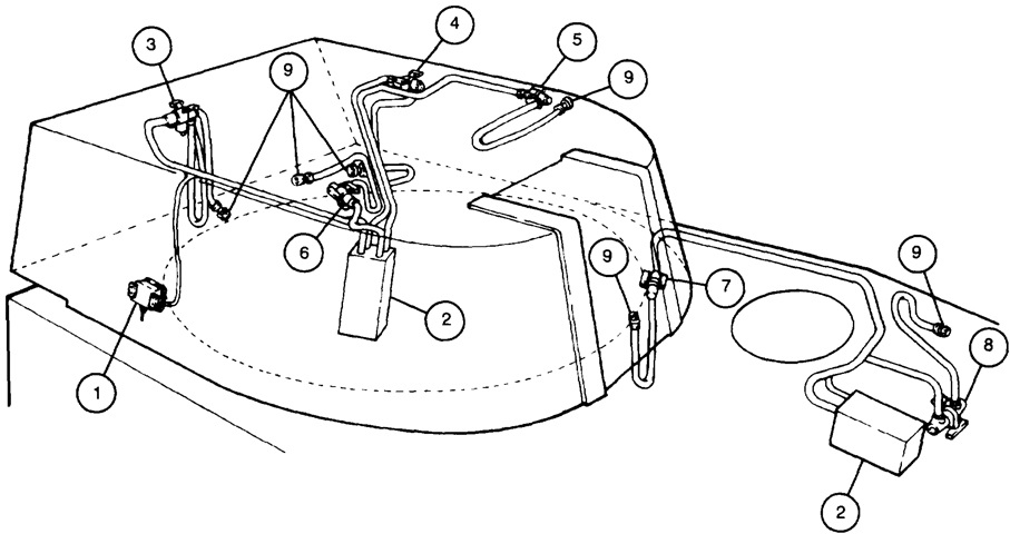
The fuel tanks and tubes for M109s up to serial number 1122 are diagrammed in this drawing. (Picture from TM 9-2350-217-20 C7.)
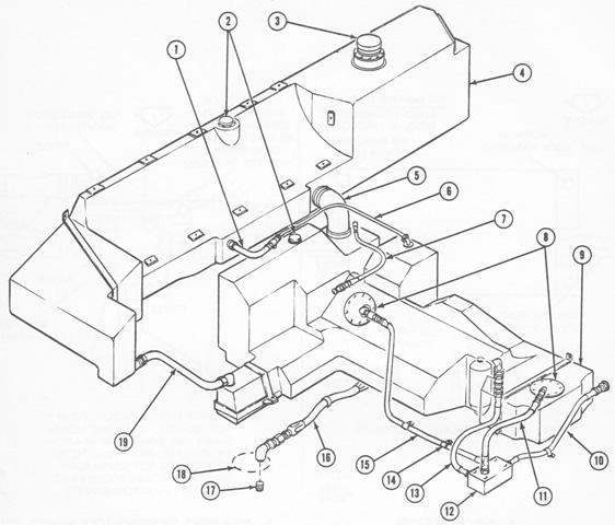
The fuel tanks and tubes for M109s after serial number 1122 are diagrammed in this drawing. 1. Lower fuel tank-to-upper fuel tank breather hose. 2. Fuel level transmitter. 3. Fuel filler cap and filter. 4. Upper fuel tank. 5. Upper tank-to-lower tank main drain hose assembly. 6. Lower fuel tank breather tube. 7. Engine-to-lower tank fuel return hose assembly. 8. Electric fuel pump. 9. Lower fuel tank. 10. Fuel distribution fitting-to-personnel heater hose assembly. 11. Fuel pump-to-fuel distribution fitting hose assembly. 12. Fuel distribution fitting. 13. Fuel distribution fitting-to-engine primary fuel filter hose assembly. 14. Clamp. 15. Fuel pump-to-fuel distribution fitting hose assembly. 16. Lower fuel tank drain hose. 17. Drain pipe plug. 18. Hole in hull bottom plate. 19. Upper tank-to-lower tank drain hose assembly. (Picture from TM 9-2350-217-20 C7.)
The battery compartment has been opened, revealing as well the auxiliary power slave receptacle at the top. Four 12-volt batteries were connected in series-parallel to make a 24-volt system. (Picture from TM 9-2350-217-10N.)
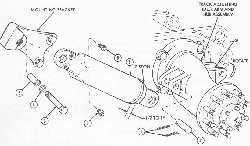
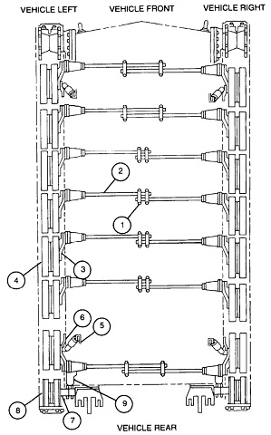
The hydraulic track adjuster and mounting bracket installed on M109s after serial number 1122 is diagrammed here; previous M109s shared the same design as found on the M108. 1. Cotter pin. 2. Pin. 3. Screw. 4. Flat washer. 5. Pivot pin. 6. Track hydraulic adjuster. 7. Input pressure fitting. 8. Bleed plug.
To increase track tension, lubricant was added to the adjuster via the input pressure fitting. Tension was decreased by removing lubricant via the bleed plug. (Picture from TM 9-2350-217-20 C7.)
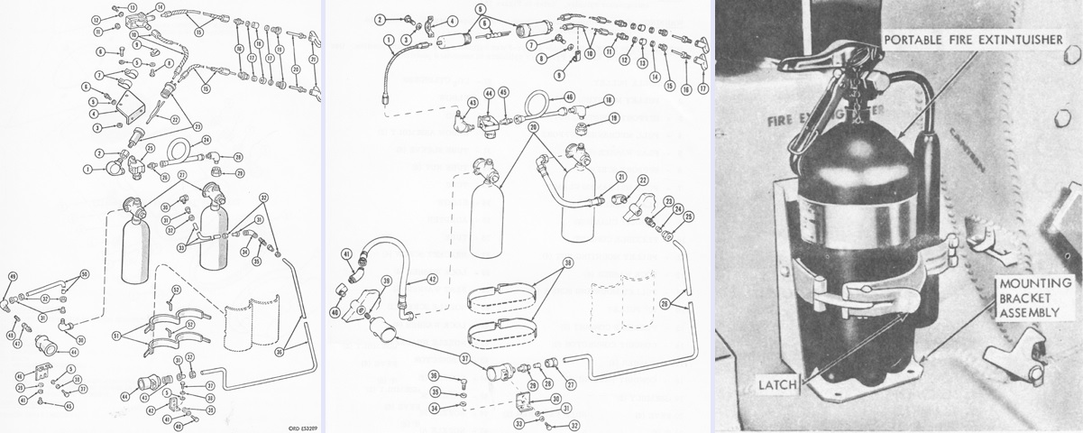
The fixed fire extinguisher system for M109s through serial number 1122 (and all M108s) is diagrammed on the left, while the system for M109s after serial number 1122 is shown in the center. In addition, a portable fire extinguisher was also carried, seen on the right. (Pictures from TM 9-2350-217-20 C7.)
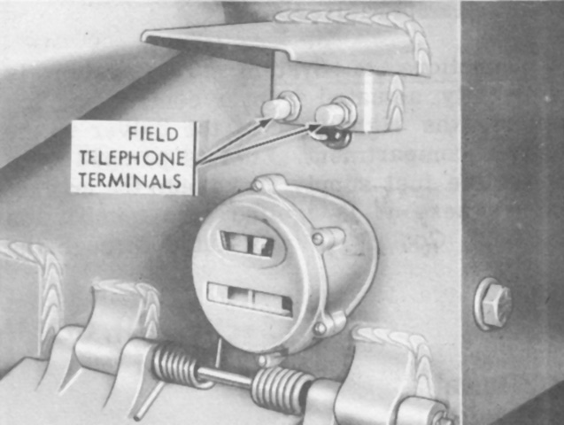
Terminals for connecting field telephones could be found on the rear hull above the right taillight. (Picture from TM 9-2350-217-10 C3.)
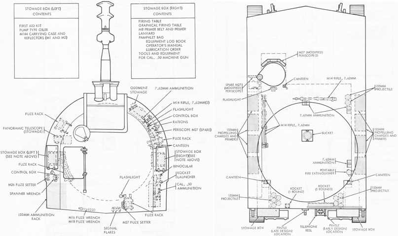
Internal stowage, including ammunition, is the subject of these diagrams. (Picture from TM 9-2350-217-10 C3.)
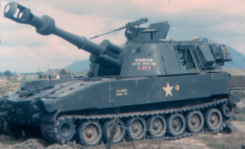
The muzzle brake and bore evacuator on the short M126 or M126A1 howitzer are obvious. The howitzer travel lock is folded down on "Bouncer's" front plate, and the .50cal MG is mounted on the turret roof. The two hatch doors on the sloping front plate above the drive sprocket were for battery access, and the travel lock is resting on the transmission access doors. The turret left side door is open, and the mushroom-like ballistic cover for the M117 panoramic telescope is elevated on the turret roof. (Picture by Jon W. Madzelan.)
The longer ordnance on this machine is strikingly different from the howitzers M126 or M126A1. (Picture from TM 9-2350-217-10N.)
The revised power control box is shown in this sketch. 4. Cab power switch. 5. Traverse control switch. 6. Elevation control switch. 7. Cab power switch indicator light. 8. Traverse control switch indicator light. 9. Gunner's control handle. 10. Actuator. 11. Traverse handwheel. (Picture from TM 9-2350-217-10N.)
The 155mm howitzer M185 weighed 4,320lb (1,960kg) total, with the tube weighing 3,166lb (1,436kg). It conferred a ~24% increase in range when firing the M107 high-explosive shell compared to the howitzer M126. (Picture from TM 9-2350-217-10N.)
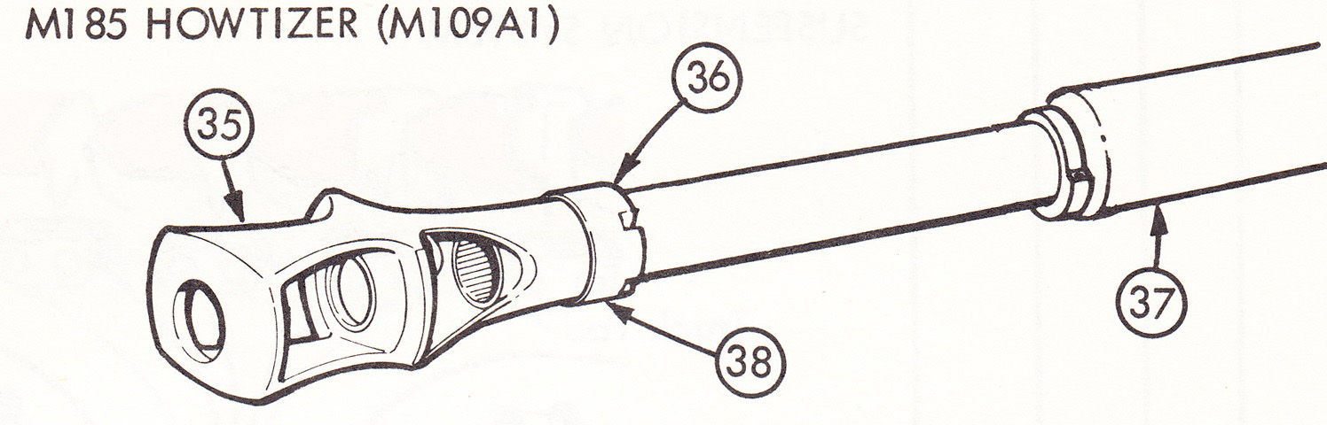
The muzzle of the M185 is shown here. 35. Muzzle brake. 36. Key. 37. Evacuator. 38. Thrust collar. (Picture from TM 9-2350-217-10N.)
The new design of bore evacuator is shown in this drawing with the thrust collar (left) and evacuator chamber highlighted in pink. (Picture from TM 9-2350-217-10N.)
The functioning of the M185's travel lock is illustrated here. (Picture from TM 9-2350-217-10N.)
The long howitzer tube but unextended turret bustle between the stowage baskets mark this vehicle as an M109A1. These marines were taking part in Operation CAX 1-2-82. (Picture taken 1 Nov 1981 by Cpl J. A. Daniels; available from the National Archives.)
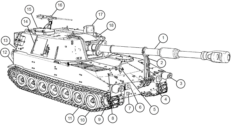
Details of the front of the vehicle are shown here. 1. Cannon and howitzer assembly. 2. Travel lock assembly. 3. Headlight. 4. Final drive drain plug. 5. Engine oil level check access door. 6. Front lifting eye. 7. Front towing eye. 8. Bilge pump outlet. 9. Drive sprocket and hub. 10. Road wheels. 11. Track assembly. 12. Hull. 13. Cab. 14. Cab side door. 15. Commander's cupola. 16. M2 caliber .50 machine gun. 17. Panoramic telescope ballistic cover. 18. Cab weather cover. (Picture from TM 9-2350-311-10 C6.)
The rear of the howitzer is sketched here. 19. Projectile access door. 20. Cab lifting eye. 21. Bustle door. 22. Rear lifting eye. 23. Exhaust deflector. 24. External power receptacle (M109A4/M109A5). 25. Idler wheels. 26. Stoplight and blackout light. 27. Towing pintle assembly. 28. Rear hull door. 29. M13 decontamination apparatus. 30. Reel bracket. 31. Spade. 32. Stowage box. (Picture from TM 9-2350-311-10 C6.)
The top of the howitzer is sketched here. 33. Air intake grille. 34. Radiator fan access door. 35. Exhaust grille. 36. Radiator cap access door. 37. Personnel heater exhaust deflector. 38. Fuel tank access door. (Picture from TM 9-2350-311-10 C6.)
39. Cab access cover. 40. Gunner's escape hatch. 41. M140 alignment device mount. 42. Fire extinguisher handle. 43. Personnel air vent ventilator. 44. Driver's hatch cover. 45. Battery compartment access doors. 46. Transmission access doors. (Picture from TM 9-2350-311-10 C6.)
Major internal hull components are detailed in this picture. 1. Coolant surge tank. 2. Fuel tank and pumps. 3. Air cleaner. 4. Personnel heater. 5. Fixed fire extinguisher. 6. Canister stowage. 7. Projectile racks. 8. Accessory control box. 9. Driver's seat assembly. 10. Portable and driver's instrument panels. 11. Driver's controls. 12. M2A2 air purifier (M109A4/M109A5). 13. Battery. (Picture from TM 9-2350-311-10 C6.)
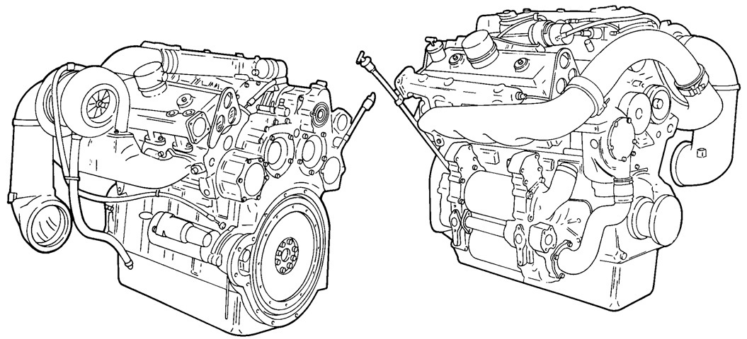
The Model 7083-7396 engine is seen from the left rear and right front, respectively. This engine featured a side-mounted TA18A90 turbocharger; crankshaft and camshaft dampers; crosshead piston and connecting rod assembly; accessory drive; throttle delay assembly; Model N80 fuel injectors; remote mounted fuel filter and strainer; airbox heater air pump; and water manifolds. Bore and stroke were 4.25" (10.8cm) and 5.0" (13cm), respectively, for a displacement of 568in³ (9.31L). The engine was 42.4" (108cm) long, 54.9" (139cm) wide, 41.6" (106cm) tall, and weighed 2,495lb (1,132kg). (Picture from TM 9-2815-202-34 C1.)
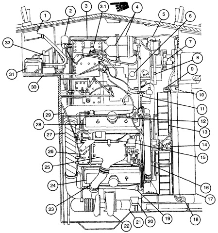
The layout of the powerplant and drivetrain compartments is sketched here for vehicles with the Model 7083-7396 engine. 1. Rectifier. 2. Secondary fuel filter. 3. Transmission. 3.1. Transmission and engine oil sampling valves. 4. Engine oil filter. 5. Primary fuel filter. 6. Transmission dipstick/filler cap. 7. Universal joint (right). 8. Transmission breather. 9. Coolant aeration detector. 10. Bilge pump. 11. Engine oil dipstick. 12. Engine oil filler cap. 13. Radiator fan assembly. 14. Surge tank pressure relief valve. 15. Flame heater igniter. 16. Coolant crossover tube. 17. Radiator. 18. Radiator filler cap. 19. Engine coolant temperature transmitter. 20. Fixed fire extinguisher nozzle. 21. Engine exhaust outlet duct. 22. Turbocharger. 23. Engine air inlet tube. 24. Cylinder head rocker cover (rear). 25. Engine intake air blower. 26. Engine speed governor. 27. Exhaust crossover tube. 28. Cylinder head rocker cover (front). 29. Right engine exhaust manifold. 30. Master relay. 31. Voltage regulator. 32. Universal joint (left). (Picture from TM 9-2350-311-10 C6.)
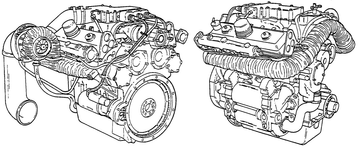
The low heat rejection Model 7083-7391 engine is seen from the left rear and right front, respectively. This engine featured a side-mounted TV8405 turbocharger; a bypass blower system; crankshaft and camshaft dampers; crosshead piston and connecting rod assembly; accessory drive; remote mounted fuel filter and strainer; water manifolds; Model 7590 fuel injectors; low heat rejection cylinder heads; insulated turbocharger turbine housing and exhaust manifolds; and glow plugs and a glow plug controller. Bore, stroke, and other dimensions were unchanged from the Model 7083-7396. (Picture from TM 9-2815-202-34 C1.)
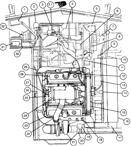
The layout of the powerplant and drivetrain compartments is sketched here for vehicles with the Model 7083-7391 engine. 1. Rectifier. 2. Secondary fuel filter. 3. Transmission. 3.1. Transmission and engine oil sampling valves. 4. Engine oil filter. 5. Primary fuel filter. 6. Transmission dipstick/filler cap. 7. Universal joint (right). 8. Transmission breather. 9. Coolant aeration detector. 10. Bilge pump. 11. Engine oil level gage. 12. Engine oil filler cap. 13. Radiator fan assembly. 14. Surge tank pressure relief valve. 15. Coolant crossover tube. 16. Radiator. 17. Radiator filler cap. 18. Engine coolant temperature transmitter. 19. Fixed fire extinguisher nozzle. 20. Engine exhaust outlet duct. 21. Turbocharger. 22. Engine air inlet tube. 23. Cylinder head rocker cover (rear). 24. Engine intake air blower. 25. Engine speed governor. 26. Exhaust crossover tube. 27. Glow plug controller. 28. Cylinder head rocker cover (front). 29. Right engine exhaust manifold. 30. Master relay. 31. Voltage regulator. 32. Universal joint (left). (Picture from TM 9-2350-311-10 C6.)
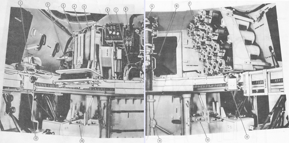
The left front of the cab is drawn here. 1. Operating handle (breech mechanism). 2. Dome light switch. 3. Rammer actuating valve control handle. 4. Firing mechanism manual control lever. 5. Rammer handle. 6. Turret lock. 7. M3 electrical air heater (M109A4/M109A5). 8. Accessory control box. 9. Manual traverse handwheel. 10. Gunner's control assembly handle. 11. Gunner's selector switch box assembly. 12. Equilibration handpump assembly. 13. M145/M145A1 telescope mount. 14. M117/M117A2 panoramic telescope. (Picture from TM 9-2350-311-10 C6.)
The rear of the cab is drawn here. 8. Power pack assembly. 9. External filter (M109A4/M109A5). 10. Air line filter and hygroscopic breather (M109A4/M109A5). 11. Cab ammunition rack assembly. 12. Canister rack propellant. (Picture from TM 9-2350-311-10 C6.)
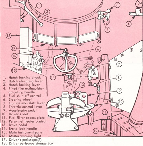
This is the driver's position. 1. M42 driver's periscope. 2. Hatch locking lever. 3. Fuel shut off control assembly handle. 4. Master warning light. 5. Fire extinguisher handle. 6. Transmission shift control lever. 7. Manual control handle [used to engage parking brake]. 8. Hand throttle control lever. 9. Accelerator pedal. 10. Driver's heater outlet duct. 11. Driver's seat vertical adjusting lever. 12. Brake pedal. 13. Steering wheel. 14. Driver's fixed instrument panel. 15. M3 electrical air heater (M109A4/M109A5). 16. Dome light switch. 17. Portable instrument panel [used when driver is in raised position]. (Picture from TM 9-2350-311-10 C6.)
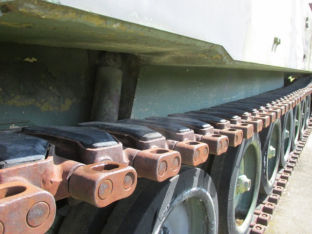
Suspension components are diagrammed here. 1. Torsion bar anchor. 2. Torsion bar. 3. Road wheel arm. 4. Road wheel. 5. Shock absorber. 6. Bump stop. 7. Idler arm assembly. 8. Idler wheel. 9. Track adjuster. (Picture from TM 9-2350-311-10 C6.)
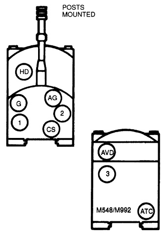
The mounted crew positions are shown here. HD: howitzer driver. AG: assistant gunner. G: gunner. 1-3: cannoneers. CS: chief of section. AVD: ammo vehicle driver. ATC: ammo team chief. (Picture from TM 9-2350-311-10 C6.)
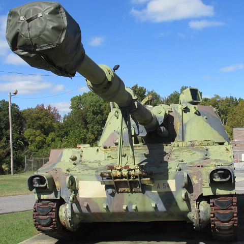
The large howitzer and imposing muzzle brake of this M109A2 stand out. The travel lock mounting point was moved down to the extreme front with the installation of the longer howitzers. The mount for the .50cal M2HB machine gun is visible on the turret's right side, and the new protective ballistic hood for the panoramic telescope M145 is on the turret's left, facing to the right. (Picture courtesy Armor Foto.)
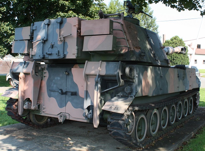
This rear view shows the lengthened turret bustle, which is flanked on either side by stowage racks. The back of the turret can be contrasted to the M109A1 above, where there is no bustle visible between the rear stowage baskets. The stabilization spades are folded up on either side of the hull rear. (Photo by Richard S. Eshleman.)
The turret stowage bustle and commander's cupola hatch are open on this vehicle, and the stabilization spades are lowered. (Photo by Richard S. Eshleman.)
The NBC system is sketched here. The system would not protect against carbon monoxide, and in temperatures below 32°F (0°C), the M3 heaters were to be run for 15 minutes before the crew's M25A1 masks were connected to prevent the risk of frostbite. 1. NBC control box assembly. 2. M2A2 air purifier. 3. Section chief's M3 electrical air heater. 4. Cannoneer no.1's M3 electrical air heater. 5. Gunner's M3 electrical air heater. 6. Assistant gunner's M3 electrical air heater. 7. Cannoneer no.2's M3 electrical air heater. 8. Driver's M3 electrical air heater. 9. Orifice connectors to M25A1 field protective masks. (Picture from TM 9-2350-311-10 C6.)
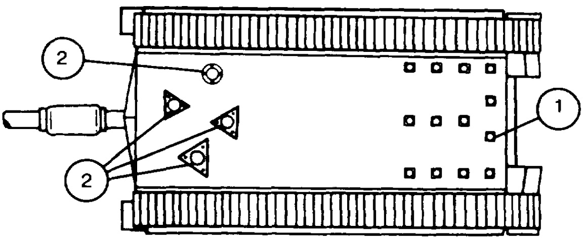
The locations for the 13 drains added to the M109A4 are marked as 1. Cover plates for hull access holes are labeled as 2. (Picture from TM 9-2350-311-10 C6.)
From this angle and distance, the M109A5 is difficult to distinguish from the M109A4, or indeed earlier howitzers, whence it was derived.
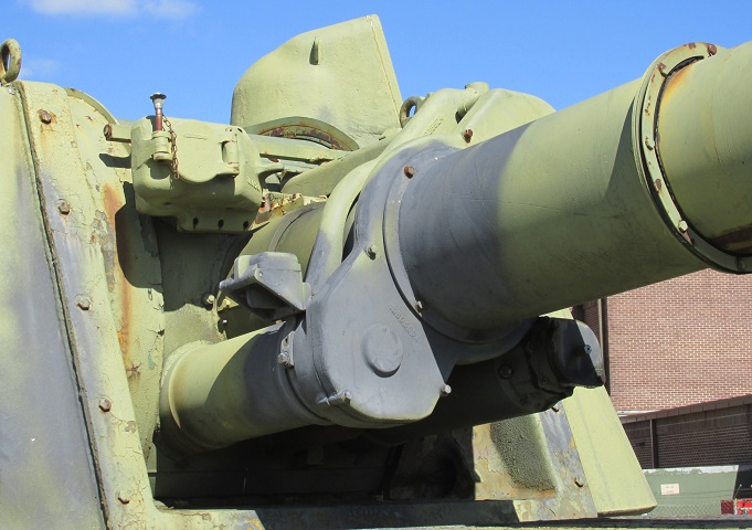
Here the vehicle can be positively identified. The forward-facing optic with the closed, hinged cover is the offset periscope M42 that allowed the telescope M118 series to see around the muzzle brake. Enclosing the howitzer tube to its top left and bottom right is the variable recoil mechanism, attached to the upper and lower recoil cylinders.
Zooming in on the base of the howitzer tube in the previous image, we can see the torque key that fits into the keyway on the cradle mount to prevent the tube from rotating. On the howitzer mount M178 this was held in place by ten cap screws. On this M109A5's mount M182, only four cap screws are present on each side.
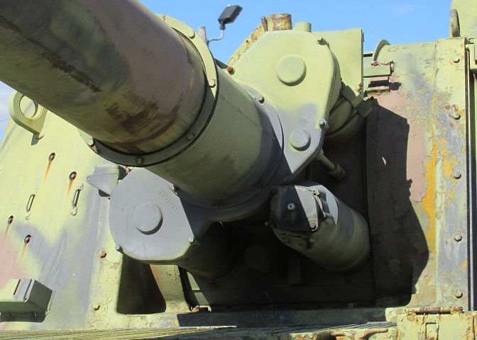
The recuperator can be seen to the howitzer mount's bottom left, unconnected to the cover of the variable recoil mechanism. A dust shield is attached to the base of the howitzer tube and the variable recoil mechanism cover.
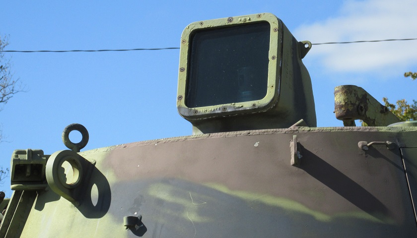
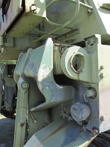
A closeup of the cover for the panoramic telescope is provided here, and it is pointing to the vehicle's front left. The commander's machine gun mount can be seen in the background. In front of the turret lifting eye can be seen the mount for the M140 or M140A1 alignment device, which ensures the panoramic telescope and the howitzer tube are aligned.
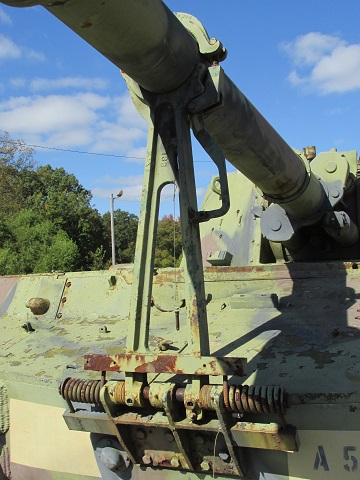
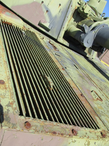
The driver's hatch is highlighted in this image. Three periscopes M42 ring his position, and a handle for external activation of the vehicle's fire extinguishers is enclosed in a guard on the hull roof. Between the driver's hatch and the turret is the grille for the personnel air vent ventilator, and to the driver's right is the large air intake grille. A mounting bracket for the antenna of the radar chronograph M90 is attached to the upper recoil cylinder.
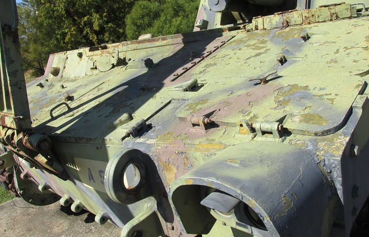
Two access doors for the battery compartment are on the front hull slope directly behind the left headlight, and inboard of the lower battery compartment door are access doors for the transmission. On the more vertical slope of the front of the engine compartment can be seen the engine oil level check access door and, outboard of this, the bilge pump outlet. Beside the headlight cluster are a lifting eye above and a towing eye below.
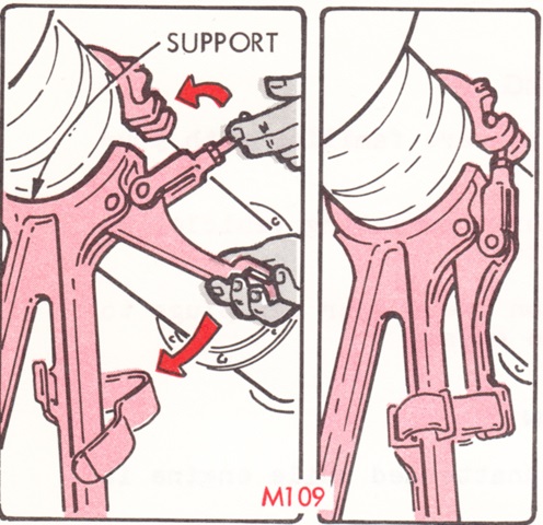
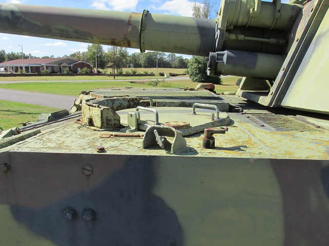
Driving with the howitzer unsecured could lead to serious damage, so the there were locks for both the turret and howitzer tube. To release the tube, the locking pin was removed (already done on this vehicle: it can be seen hanging on a string between the struts of the travel lock), then the handle was raised and the tube elevated until it cleared the travel lock cradle rest. The travel lock was folded to the rear to be stowed on the engine compartment deck.
The exhaust grille is in the center of this picture, with the exhaust deflector just visible to the upper left of the image. Just inboard of the exhaust grille is the radiator fan access door; the hinge near the turret shows the location of the radiator cap access door.
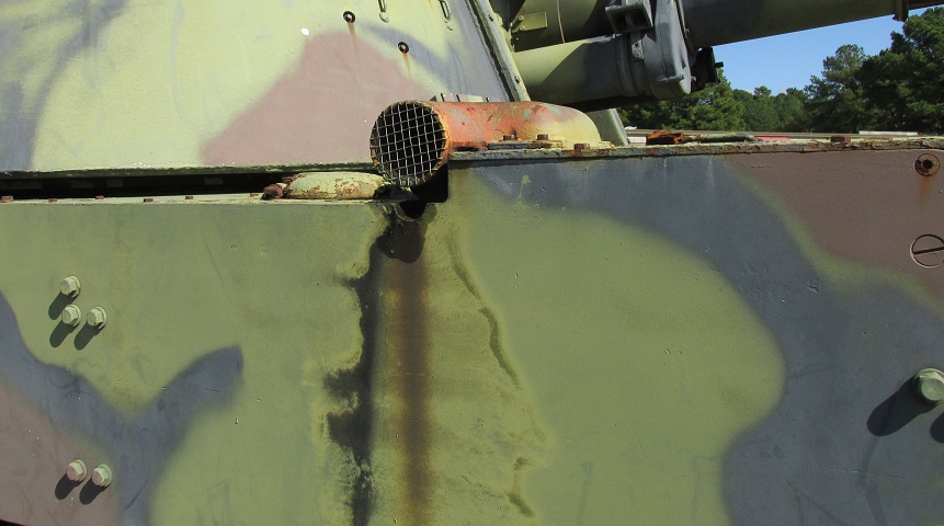
The exhaust deflector was mounted at the rear of the exhaust grille. Behind it is a fuel tank access door.
The location of the right rear shock absorber can be gleaned from this picture.
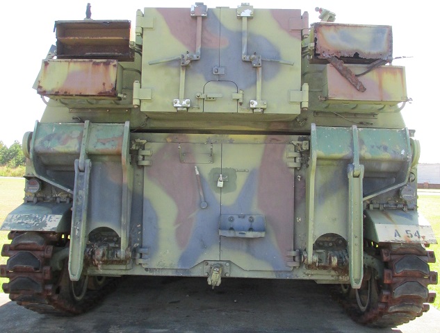
This vehicle was converted from an earlier-production M109A4, shown by the double doors on the hull rear. The locking handle is pointed up towards the bracket for communication wire, and a mount for a liquid can is on the right hull door. Recoil spades flank the hull doors, and a towing pintle is below them. The turret bustle can be opened either by the two large doors or by the smaller tunnel-shaped door in the bottom center, which allowed projectiles to be passed into the cab with greater security for the turret crew compared to the large doors. Stowage boxes flank the turret bustle.
The right rear of the hull is detailed here. Above the rear lifting eye is the connection for external telephone communication, and below the lifting eye is an external power receptacle common to the M109A4 and M109A5. Below the power receptacle is a stoplight and blackout light. A stowage box is hidden by the spade, and the turret stowage boxes are mounted on stowage baskets.
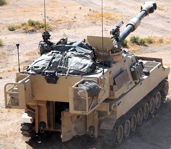
The new turret with a full-width bustle can be seen on this vehicle from C Battery, 41st Field Artillery Regiment, 1st Armored Brigade Combat Team, 3d Infantry Division. The remote-control travel lock can be contrasted to the vehicles above. A blank adapter is on the .50cal MG, and the crew are wearing NBC protective gear. (Picture taken 1 Aug 2017 by SGT Joseph Truckley; available from the Defense Video & Imagery Distribution System.)
The enlarged bustle is more apparent in this rear view of a howitzer from the 155th Armored Brigade Combat Team, and the stowage baskets attached to the bustle are swung back. This can help decrease the vehicle's width. (Picture taken 2 Jun 2017 by SGT Edward Lee; available from the Defense Video & Imagery Distribution System.)
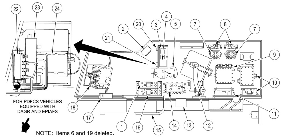
The locations of major internal components on the right side of the cab are illustrated here. 1. VRC radio (voice). 2. Hydraulic control box. 3. AFCS Display Unit (DU)/PDFCS Display Unit (DU). 4. Keypad (PDFCS). 5. Chief of section control handle. 7. Full Function Crew Station (FFCS). 8. M3 heaters. 9. PDIU (AFCS). 10. Automatic fire control system/Paladin digital fire control system batteries. 11. AFCS Power Conditioner Unit (PCU)/PDFCS Power Conditioner Unit-2 (PCU-2). 12. Commander's seat assembly (stowed). 13. AFCS Azimuth tachometer/PDFCS azimuth cover plate and shorting plug. 14. Master Control Station (MCS). 15. Footrest (stowed). 16. VRC radio (digital). 17. Vehicle Motion Sensor (VMS) modem. 18. AFCS Computer Unit (ACU)/PDFCS Computer Unit (PDCU). 20. Boot dongle (PDFCS) (Will be removed from vehicles equipped with EPIAFS [Enhanced Portable Inductive Artillery Fuze Setter, which can initialize the global positioning system for guided projectiles and provides automated fire mission transfer]). 21. Paladin Serial Interface Adapter Device (PSIAD) (PDFCS). 22. Paladin Serial Interface Adapter Device (PSIAD) (For vehicles equipped with PDFCS, DAGR [Defense Advanced GPS Receiver], and EPIAFS). 23. Platform Interface Adapter (PIA) (For vehicles equipped with PDFCS, DAGR, and EPIAFS). 24. PIK [Platform Integration Kit for the EPIAFS, which is a data processor that manages data streams from multiple sources in the system] (For vehicles equipped with PDFCS, DAGR, and EPIAFS). (Picture from TM 9-2350-314-34-2 C4.)
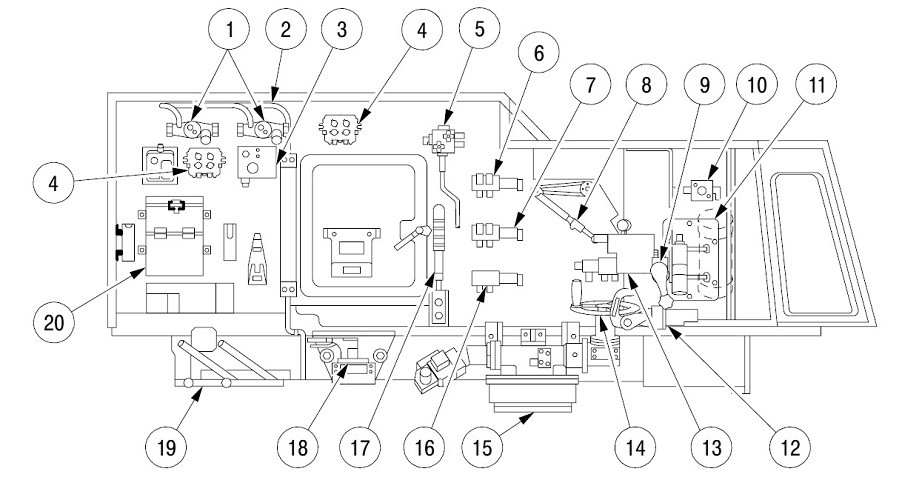
The locations of major internal components on the left side of the cab are illustrated here. Text in brackets has been added. 1. Heater (M3). 2. Driver's hose. 3. MCS [Microclimate Conditioning System] control box. 4. Full function crew station (FFCS). 5. Equilibration manifold. 6. Elevation selector valve. 7. Azimuth selector valve. 8. Pantel [panoramic telescope] linkage. 9. Elevation hand pump. 10. Return manifold. 11. Hydraulic interior compartment panel. 12. Gunner's control handle. 13. Fuse manifold. 14. Handwheel assembly. 15. Turret traverse mechanism. 16. Traverse limit valve. 17. Equilibration hand pump. 18. Turret lock. 19. Crew seat. 20. Periscope box. (Picture from TM 9-2350-314-34-2 C4.)
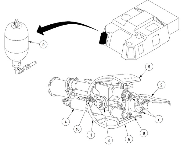
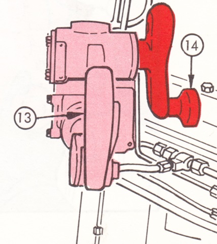
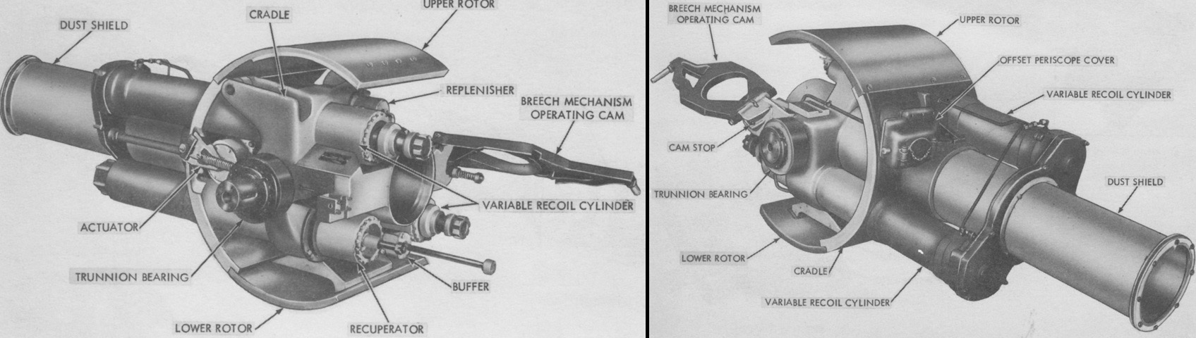
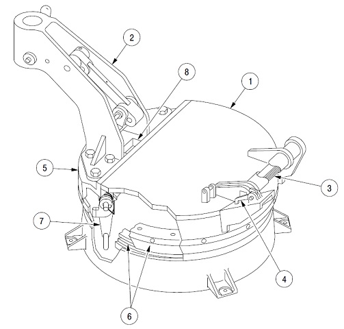
The mount M182A1 is illustrated here. 1. Cradle. 2. Breech operating handle cam. 3. Trunnion bearing. 4. Recuperator cylinder. 5. Upper rotor shield. 6. Lower rotor shield. 7. Variable recoil cylinders (2). 8. Buffer cylinder. 9. Replenisher accumulator. 10. Actuator and linkage.
The variable recoil system shortens the recoil length for higher elevations. The recuperator returns the howitzer to battery, and the buffer governs the recuperator's slamming action and works to ease the ordnance into battery. (Picture from TM 9-2350-314-34-2 C4.)
The breech mechanism of the howitzer M284 is shown here. 1. Breechblock. 2. Carrier. 3. Operating crank. 4. Obturator. 5. Firing mechanism. 6. Operating handle. (Picture from TM 9-2350-314-34-2 C4.)
Parts of the commander's cupola are detailed in this image. 1. Hatch cover. 2. Machine gun support assembly. 3. Torsion bar. 4. Spring-loaded latch. 5. Cupola body assembly. 6. Race rings. 7. Spring-loaded latch (rotation). 8. Periscope slot. (Picture from TM 9-2350-314-34-2 C4.)
