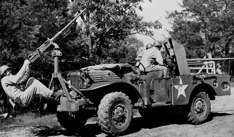
37mm Gun Motor Carriage M6.
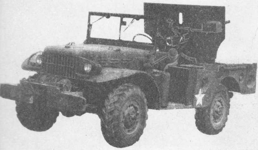
Although it makes for a dramatic picture, the .50cal machine gun mount on the front of this M6 was a field modification added by the Headquarters Company of the 5th Armored Maintenance Battalion. The machine gunner's feet are resting on the self-recovery winch. The fuel tank pressure cap is visible below the axe handle, and a reflector light is aft of the fuel tank cap. Scant protection was offered by the gun shield, but this was the only armor available on the vehicle. An ammunition rack was placed at each corner of the fighting compartment, and the white star is painted on the exterior of one of these racks. A ration box is just in front of this ammo rack, and a fuel container is on the running board in front of the ration box. The windshield is folded forward onto the hood. Note the reversed tread on the front driver's tire. (Picture taken 6 Jun 1943 by Pvt. J.F. Albert; available from the U.S. Army Center of Military History.)
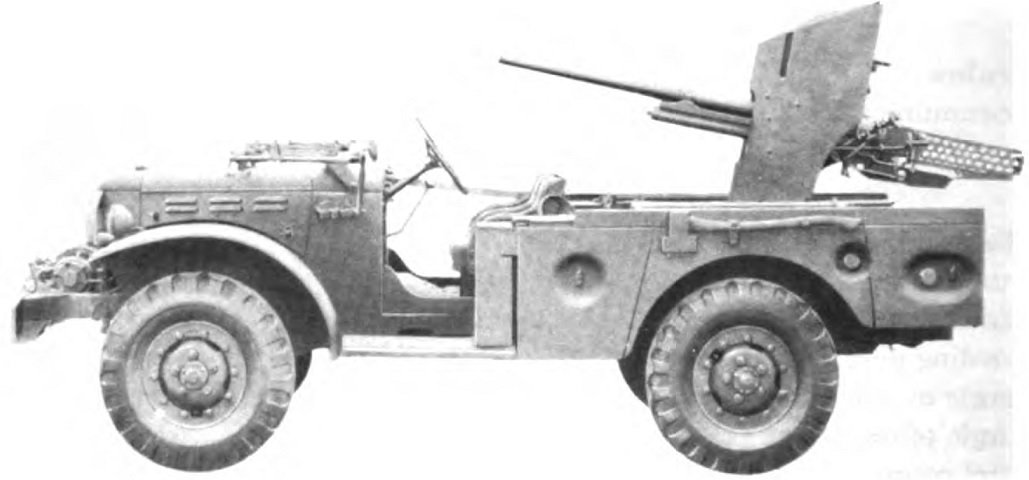
This more stock example has not had a machine gun added, and the 37mm gun is facing forward. Firing normally took place with the gun oriented to the rear since full depression could not be obtained toward the front. (Picture from TM 9-2800 Standard Military Motor Vehicles.)
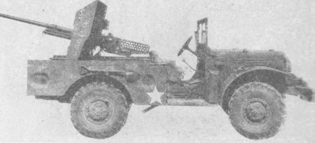
Seen from the opposite side with the ordnance traversed behind, the gun overhang to the rear can be gleaned. (Picture from FM 30-40 Military Intelligence Identification of United States Armored Vehicles.)
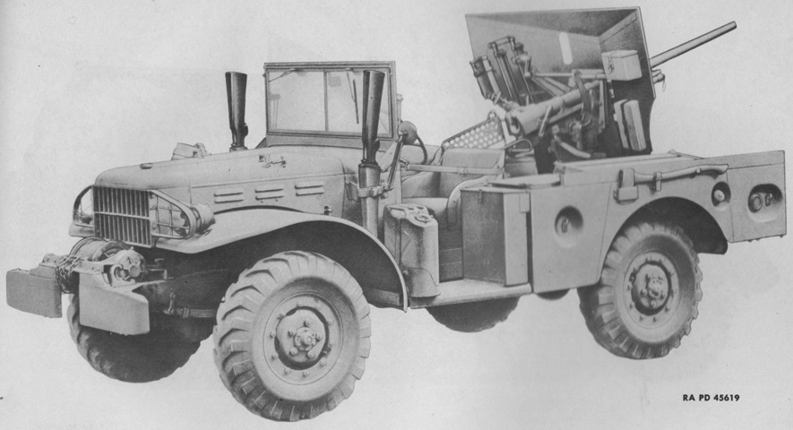
The gun is elevated to the rear, and a rifle is stowed on each side of the engine cowling. (Picture from Modern Ordnance Materiel.)
The rear view mirror helped the driver see around the gun shield. The shield design seen in this image was replaced by one that offered overhead protection and that had the bottom corners filled out as seen above. (Picture from FM 30-40 Military Intelligence Identification of United States Armored Vehicles.)
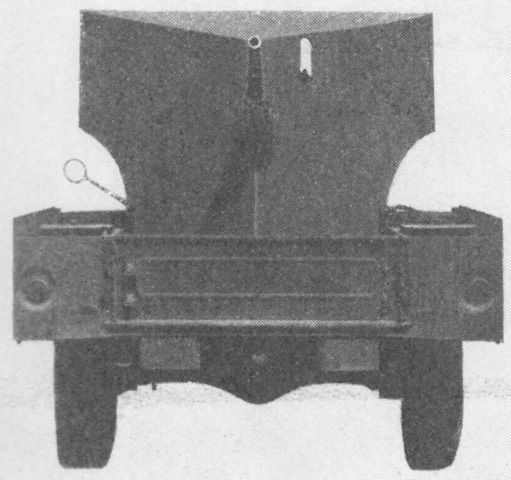
The necessity of the rear view mirror is well illustrated by this picture taken from the rear; the revised fuller gun shield would further hamper the driver's rear vision, though the added protection was doubtlessly appreciated. (Picture from FM 30-40 Military Intelligence Identification of United States Armored Vehicles.)
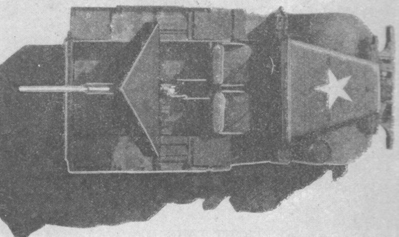
The layout of the fighting compartment can be seen in this top down view. Ammunition racks were located at the four corners of the fighting compartment, and their covers are closed here. (Picture from FM 30-40 Military Intelligence Identification of United States Armored Vehicles.)
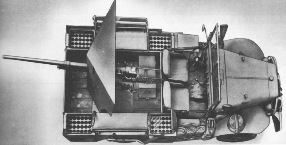
The ammunition rack covers are open here. Additionally, a water bucket is stowed on the passenger fender, and rolled blankets for the crew can be seen on the passenger running board. (Picture from Catalogue of Standard Ordnance Items, second edition 1944, volume I: Tank and Automotive.)
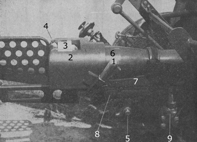
The 37mm gun is seen from the right rear while installed on its towed carriage M4. The top carriage of this mount was identical to the cradle of the pedestal mount M25 or M26. The gun weighed 191lb (86.6kg). 1. Operating handle. 2. Breech ring. 3. Breechblock. 4. Cocking lever. 5. Traveling lock hook. 6. Barrel. 7. Sleigh. 8. Recoil cylinder. 9. Elevating mechanism. (Picture from FM 23-70 37-mm Gun, Antitank, M3.)
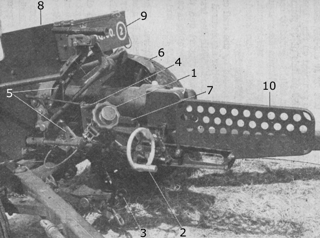
The gun on its towed carriage M4 is shown from the opposite side. Five and one-half pounds (2.5kg) of force was needed to elevate the gun, while depression required 5lb (2.3kg), and traverse in either direction required 2lb (.9kg) of force. When the traversing release handle was pulled, the traversing worm gear drive was disengaged and the gun could be traversed by free movement. A spring reengaged the handle when it was released. 1. Elevating knob. 2. Traversing handwheel. 3. Traveling lock. 4. Traversing release handle. 5. Top carriage. 6. Wheel segment. 7. Sleigh. 8. Shield. 9. Tool chest. 10. Shoulder guard. (Picture from FM 23-70 37-mm Gun, Antitank, M3.)
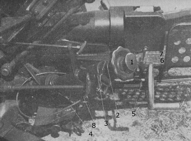
The trigger actuator is detailed in this image. 1. Plunger. 2. Disk. 3. Link. 4. Cable. 5. Trigger lever plunger. 6. Trigger lever. 7. Trigger. 8. Set screw. (Picture from FM 23-70 37-mm Gun, Antitank, M3.)
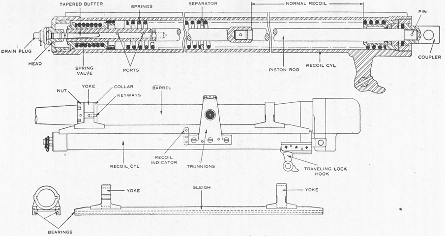
The hydrospring recoil mechanism was filled with 5 pints (2.4L) of low-pour point heavy recoil oil; normal recoil stroke was 20" (51cm) and maximum was 20½" (52.1cm). The recoil piston was attached to the gun by a coupler. As the gun was driven rearward by the forces of the fired round, the counterrecoil springs were compressed, and oil was forced to flow through apertures in the piston head. After rearward movement was arrested, the counterrecoil springs expanded, forcing the gun back into battery. The piston head valve closed the holes in the piston head upon forward movement, forcing the oil to return via ports in the piston walls and the hollow end of the piston rod. The tapered counterrecoil buffer slowed the piston rod as it neared the end of its movement by forcing oil out of the hollow portion of the piston rod, thereby preventing shock as the gun returned to battery. (Picture from FM 23-70 37-mm Gun, Antitank, M3.)
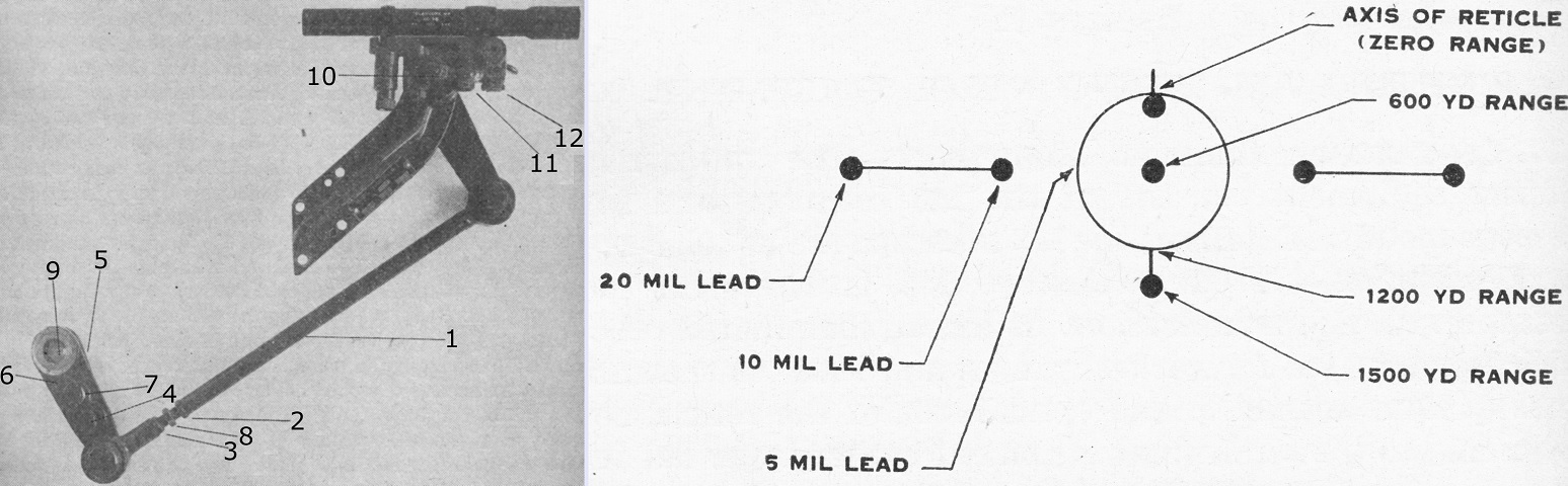
The telescope M6 is seen in the telescope mount M19 on the left. The M6 was a 1x straight tube telescope with an 11° field of view. The mount M19 was a hinged bracket that constantly assumed a parallelogram shape to keep the telescope parallel to the gun bore. 1. Link tube. 2. Locking nut. 3. Locking nut. 4. Clamping bolt. 5. Gun trunnion arm. 6. Link tube arm. 7. Eccentric. 8. Differential screw. 9. Trunnion. 10. Shaft. 11. Clamping bolt. 12. Eccentric.
The M6's reticle on the right was illuminated by a flashlight-type Mazda lamp No. 10 that could be screwed into a socket in the forward projection of the telescope mount. The zero range dot just inside the top of the 5-mil circle represented the geometric and optical axis of the reticle. The short vertical lines at the top and bottom of the circle showed the vertical axis. Other ranges and leads are labeled. (Picture from FM 23-70 37-mm Gun, Antitank, M3.)
