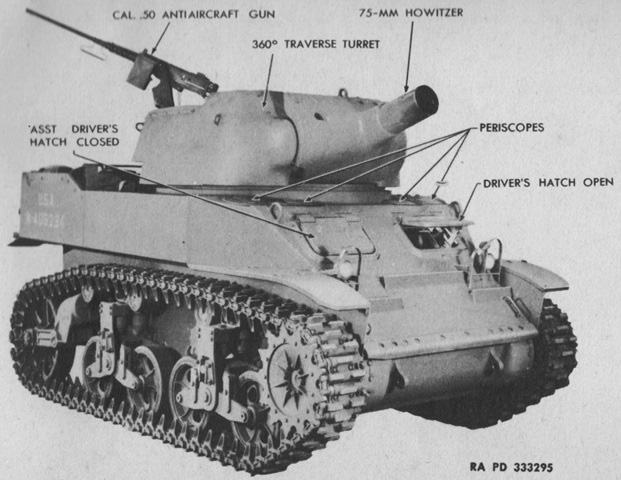
75mm Howitzer Motor Carriage M8.
The drivers' doors in the hull front plate are obvious in this 75mm HMC M8; the drivers had periscopes in the hull roof as well for driving while buttoned up. The 75mm howitzer was covered by a long flash deflector, and the muzzle of the howitzer barrel is hidden in the shadow of the flash hider. (Picture from TM 9-732B 75-mm Howitzer Motor Carriage M8.)
This later-production vehicle is equipped with sandshields and track grousers on the turret. The mount for the .50cal M2HB MG can be seen towards the rear of the open-topped turret, although the gun itself is absent. The muzzle of the howitzer can be glimpsed inside the flash hider. (Picture from TM 9-732B 75-mm Howitzer Motor Carriage M8.)
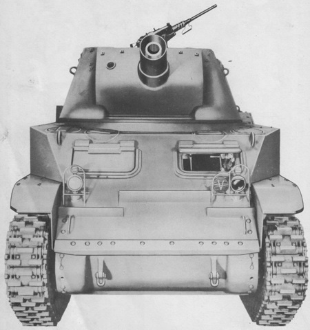
The howitzer tube can more easily be seen in this front view. (Picture from ORD 7, 8-9 SNL G-127 Organizational Spare Parts and Equipment, Higher Echelon Spare Parts, Service Parts Catalog for Carriage, Motor, 75mm Howitzer, M8.)
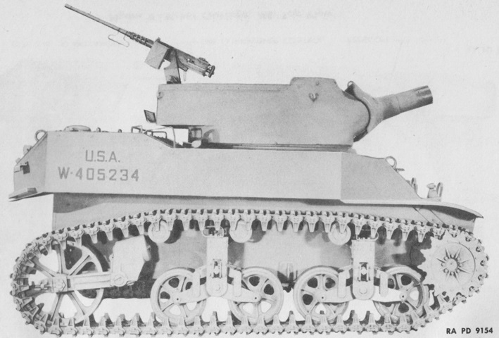
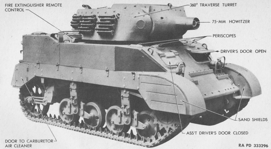
The length of the turret bustle can be seen in this side view. (Picture from TM 9-732B 75-mm Howitzer Motor Carriage, M8.)
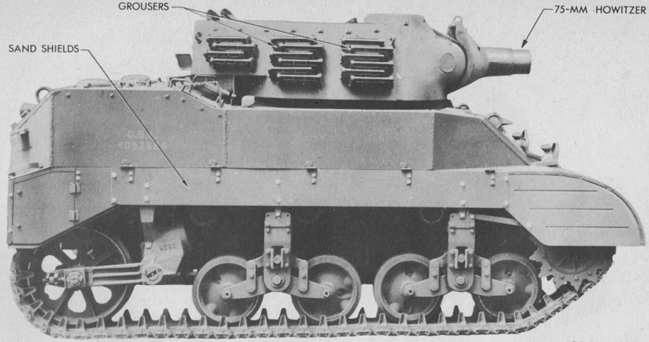
The attachments and access door of the sandshields are better viewed from the side. (Picture from TM 9-732B 75-mm Howitzer Motor Carriage M8.)
The rear of the vehicle is shown here. (Picture from TM 9-732B 75-mm Howitzer Motor Carriage, M8.)
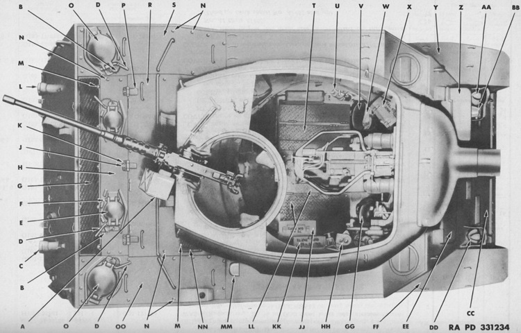
This top view shows the internal arrangements of the open-topped turret. A. Box, ammunition, assembly. B. Chain, assembly. C. Light, assembly. D. Pin, assembly. E. Cover. F. Pin; Pin, cotter. G. Screen, assembly. H. Roof, assembly. J. Hinge. K. Screw; Nut; Retainer. L. Light, assembly. M. Screw; Nut. N. Screw; Nut; Retainer. O. Cover. P. Hinge. R. Door, assembly. S. Roof, assembly. T. Floor, assembly. U. Gun, lubricating. V. Seat, driver's, assembly. W. Belt, safety. X. Box, assembly. Y. Guard, assembly. Z. Door, assembly. AA. Light, assembly. BB. Siren, assembly. CC. Plate, assembly. DD. Light, assembly. EE. Door, assembly. FF. Guard, assembly. GG. Seat, assembly. HH. Box, gear, assembly. JJ. Box, assembly. KK. Box, assembly. LL. Floor, sub, assembly. MM. Box. NN. Screen, assembly. OO. Roof, assembly. (Picture from ORD 7, 8-9 SNL G-127 Organizational Spare Parts and Equipment, Higher Echelon Spare Parts, Service Parts Catalog for Carriage, Motor, 75mm Howitzer, M8.)
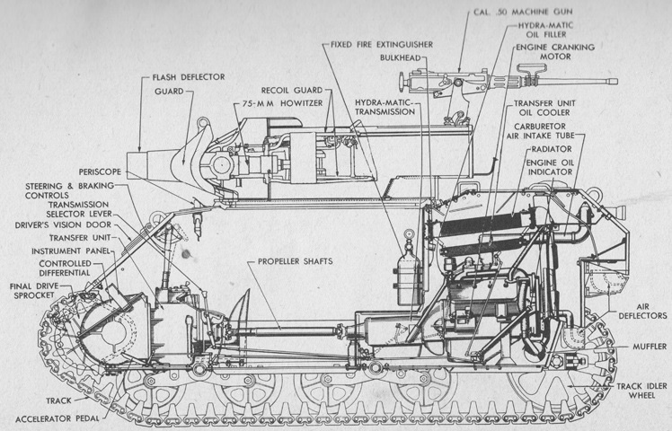
The internal layout is diagrammed in this sketch. (Picture from TM 9-732B 75-mm Howitzer Motor Carriage M8.)
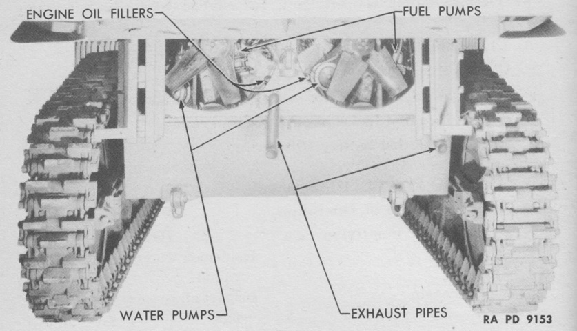
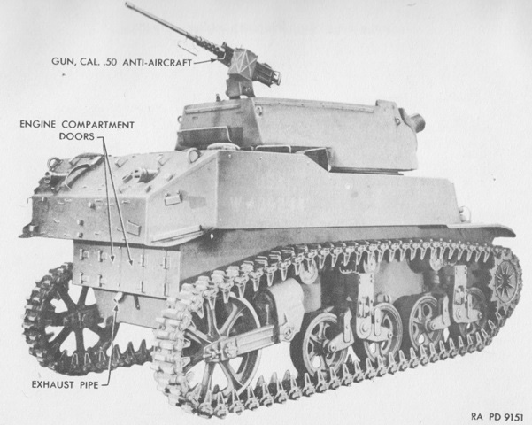
The engine compartment doors are open in this image, showing the twin engines hidden behind their fans. The tracks on this carriage are T36E6. (Picture from TM 9-732B 75-mm Howitzer Motor Carriage, M8.)
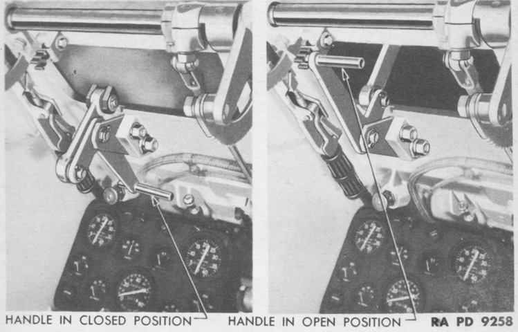
The control handle for the driver's vision door is shown in the closed and opened positions. The left steering lever is in the background. (Picture from TM 9-732B 75-mm Howitzer Motor Carriage M8.)
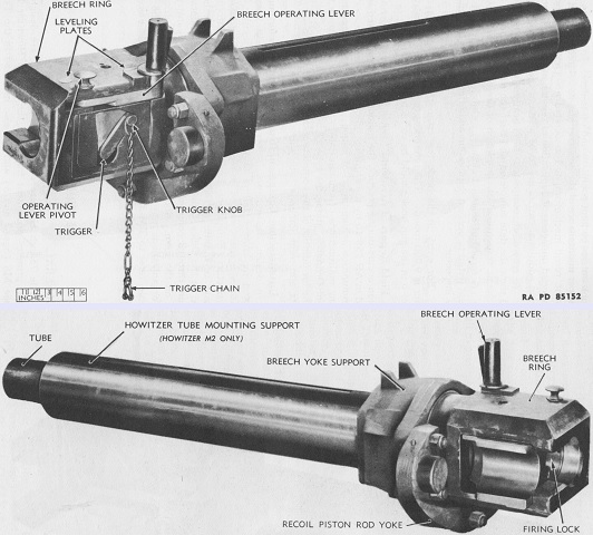
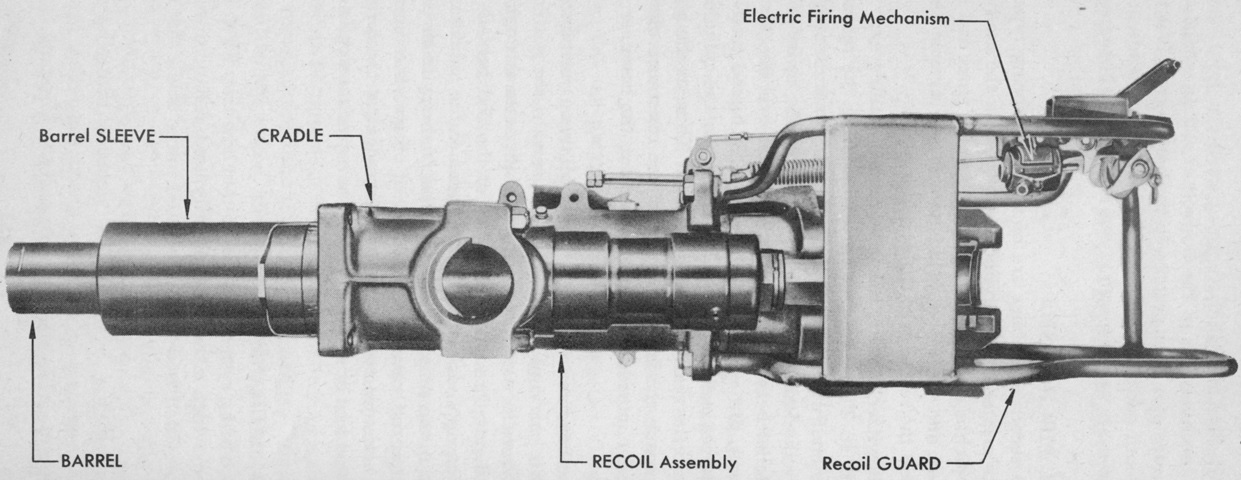
The 75mm howitzer M3 seen above weighed 421lb (191kg) and was 54.18" (137.6cm) from the muzzle to the rear face of the breech ring. Rifling was a uniform right-hand twist of one turn in 20 calibers with 28 grooves. Maximum powder pressure was 29,000psi (2,040kg/cm²). The howitzer M2 was lighter at 318lb (144kg). The howitzers were composed a tube that screwed into a breech ring, a breechblock, and an electrical and manual firing mechanism. The keyway can just be made out at the 12:00 position of the howitzer tube. (Picture from TM 9-318 75-mm Howitzers M2 and M3 (Mounted in Combat Vehicles).)
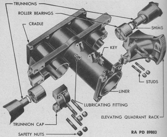
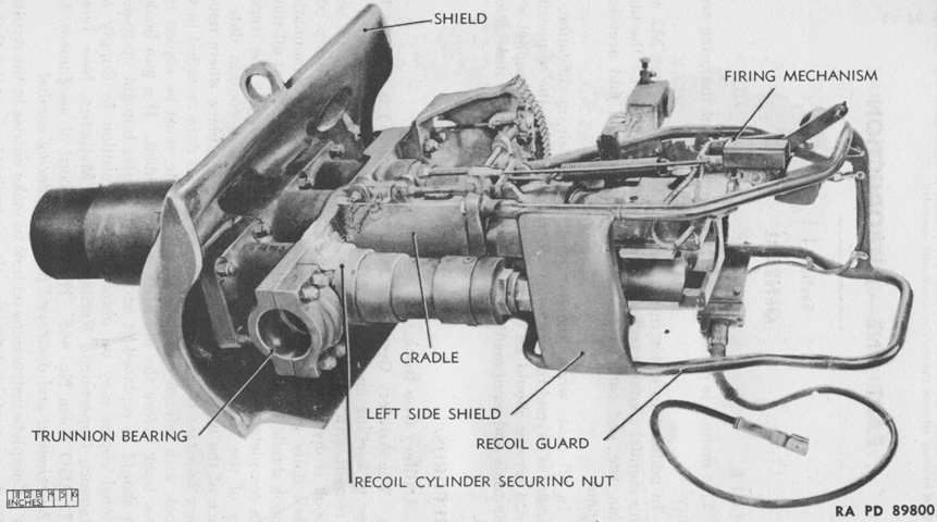
An exploded view of the cradle assembly is diagrammed in this image. The cradle retained the howitzer in its central bore, a recoil assembly on each side, and the shield on the front. Both trunnions carried double tapered roller bearings. The howitzer would slide in the cradle during recoil and counterrecoil, and was prevented from rotating by the key that rode in a groove in the howitzer tube. (Picture from TM 9-318 75-mm Howitzers M2 and M3 (Mounted in Combat Vehicles).)
The howitzer is installed in the cradle, but the shield has yet to be attached. (Picture from TM 9-732B 75-mm Howitzer Motor Carriage, M8.)
The assembled mount M7 is shown from the upper left rear. (Picture from TM 9-318 75-mm Howitzers M2 and M3 (Mounted in Combat Vehicles).)
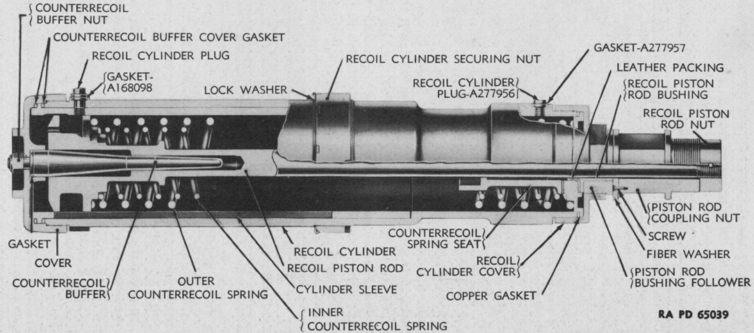
A cross-section of the recoil mechanism is drawn above. The recoil piston rod was secured to the howitzer by externally threaded coupling nuts, and consequently moved rearward with the howitzer upon firing. As the recoil piston was pulled rearward, resistance was created by oil being displaced through orifices in the piston as well as by the piston compressing the counterrecoil springs. When the firing energy was dissipated, the compressed counterrecoil springs expanded, pushing the howitzer forward. The counterrecoil buffer cushioned the last few inches of counterrecoil travel by displacing oil trapped in the end of the recoil piston, preventing a shock as the howitzer was returned to battery. Normal recoil was 11.62" (29.51cm), and each recoil cylinder contained 7⅝ pints (3.607L) of oil. (Picture from TM 9-318 75-mm Howitzers M2 and M3 (Mounted in Combat Vehicles).)
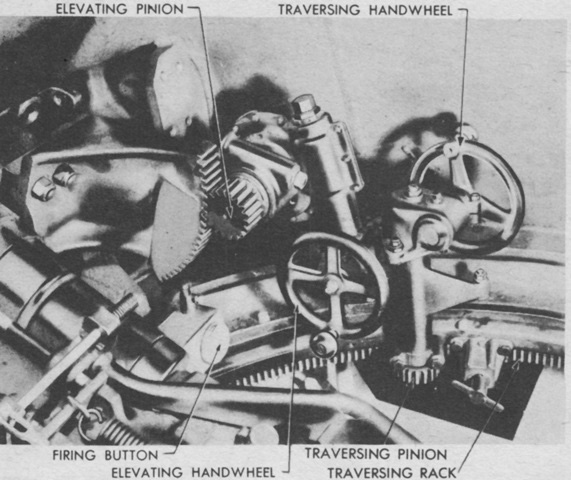
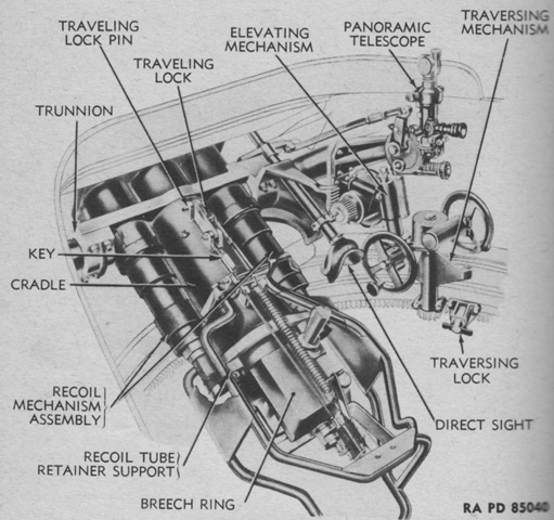
The elevation and traverse controls are highlighted here. (Picture from TM 9-732B 75-mm Howitzer Motor Carriage M8.)
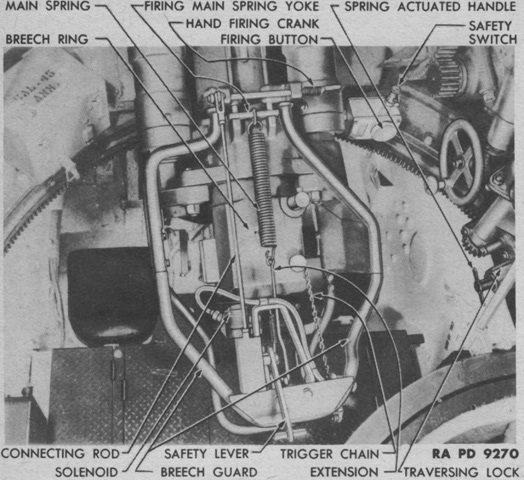
Details of the firing controls are illustrated above. (Picture from TM 9-732B 75-mm Howitzer Motor Carriage M8.)
The breech end of the howitzer and its mount are shown here. (Picture from TM 9-732B 75-mm Howitzer Motor Carriage M8.)
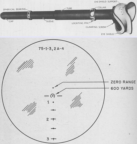
The telescope M56 is seen at the top, with its reticle sketched beneath. The M56 was a 3x erect image instrument used for direct fire, and had a 12°19' field of view. It was mounted at the right of the howitzer and moved with the howitzer in elevation. Its reticle's range scale was graduated based on firing table 75-I-3, part 2a-4, and was calibrated for use with the high-explosive shell M48, charge 4. (Picture from TM 9-732B 75-mm Howitzer Motor Carriage M8.)
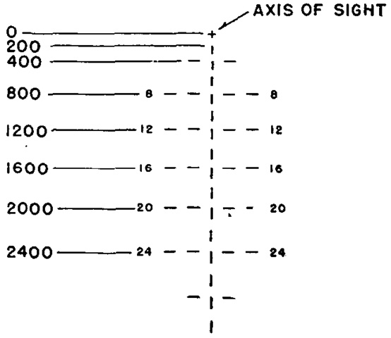
The telescope M70C was outwardly similar to the M56, but had improved optics and a broken dash reticle as seen here. (Picture from FM 17-69 C2 Crew Drill, Service of the Piece, and Gunnery (75-mm Assault Howitzer on Motor Carriage M8).)
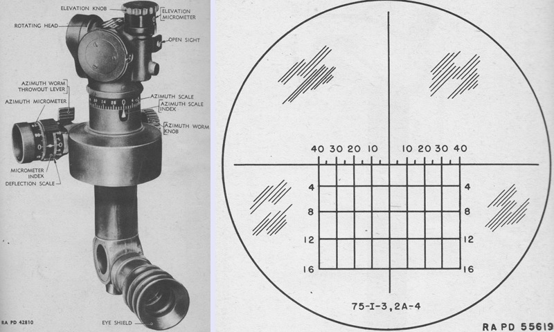
The panoramic telescope M12A5 was a 4x erect image instrument with a 10° field of view. Typically used for laying the howitzer for direction during indirect fire, the M12A5 could also be used for direct fire thanks to the range and deflection scales on its reticle. The vertical lines on the reticle were deflections in mils, while the horizontal lines were ranges in hundreds of yards. The periscope head was rotated by pressing the throw-out lever and rotating it by hand for large changes or by using the azimuth micrometer knob for small changes. The open sight on the right provided an easy way to pick up aiming points or targets. (Picture from TM 9-732B 75-mm Howitzer Motor Carriage M8.)
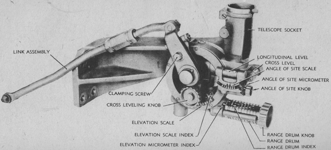
The telescope mount M44 was mounted on the right wall of the turret and accepted the panoramic telescope M12A5. It was primarily used to lay the howitzer for range or elevation when the target was not visible from the howitzer's position. When the range drum knob was turned, the range drum and elevation scale operated simultaneously, and there was a different range drum for each of the four propellant charges. The range drum was graduated in yards, while the elevation scale was graduated from 0 to 7 in steps of 100 mils. The elevation micrometer index was graduated from 0 to 100 mils in 1-mil increments. The coarse scale of the angle of site mechanism was graduated from 0 to 6 in steps of 100 mils, while the angle of site micrometer was graduated from 0 to 100 mils in 1-mil increments. The horizontal setting for the angle of site mechanism was 300, and it tipped the sight mount to the front or rear depending on how the angle of site knob was turned. Below 300 on the angle of site were negative angles, while above 300 were positive angles. The mount could be used to set in elevations from approximately -175 mils to +750 mils. The link assembly was bolted to the right side of the howitzer cradle and transmitted howitzer elevation to the telescope mount. (Picture from TM 9-732B 75-mm Howitzer Motor Carriage M8.)
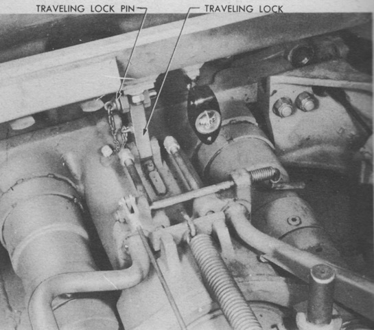
Besides the traversing lock that was actuated by turning a spring-loaded handle, the howitzer was also secured in elevation by means of a pin inserted into the traveling lock mounted on the breech. (Picture from TM 9-732B 75-mm Howitzer Motor Carriage M8.)
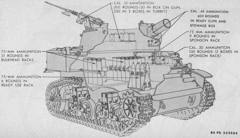
Ammunition stowage is diagrammed in this image. (Picture from TM 9-732B 75-mm Howitzer Motor Carriage M8.)
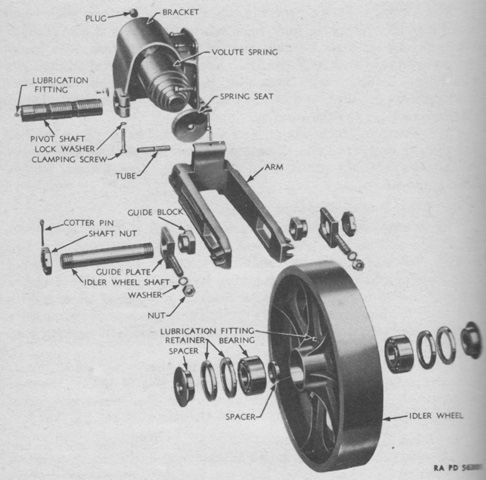
An exploded view of the vehicle's trailing idler wheel is provided here. (Picture from TM 9-732B 75-mm Howitzer Motor Carriage M8.)
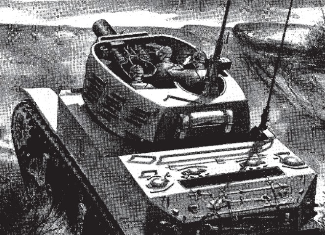
In this illustration of the action posts, the chief of section is manning the machine gun and monitoring the fall of the rounds. The gunner is just in front of the chief, and the loader is on the opposite side of the ordnance, leaving the driver as the only man in the hull. When mounted and not in action, the gunner would occupy the assistant driver's position, the loader would man the machine gun, and the chief would place himself on the turret's right side. (Picture from FM 17-69 C2 Crew Drill, Service of the Piece, and Gunnery (75-mm Assault Howitzer on Motor Carriage M8).)
