8" Self-propelled Howitzer M110.
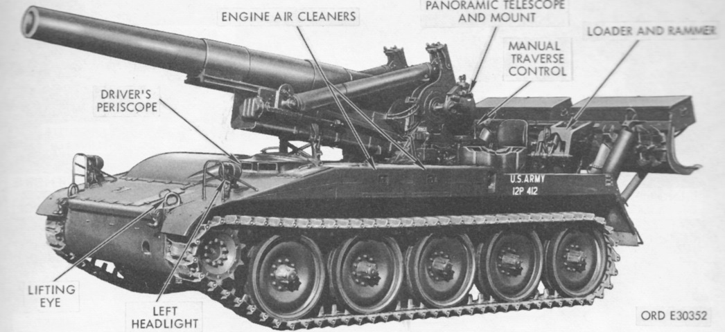
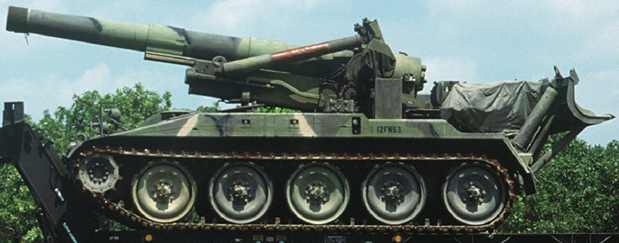
The stubby nature of the 8" howitzer M2A2 is apparent in this side view. The large hydraulic recoil spade dominates the rear of the vehicle, and the flat track suspension with the trailing idler wheel is obvious. (Picture from TM 9-2300-216-10.)
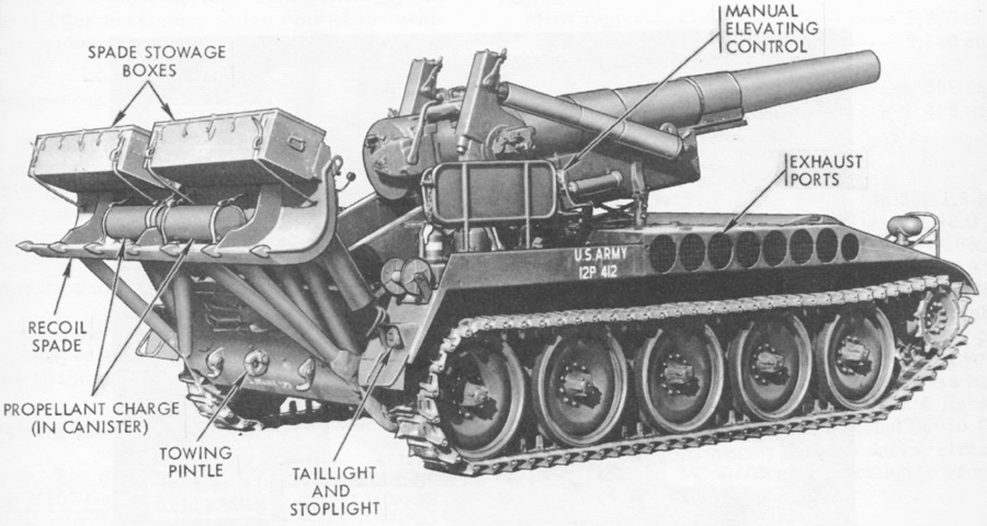
With real estate at a premium, even the recoil spade was used for stowage. A seat for the howitzer crew is folded up at the right rear corner of the hull. (Picture from TM 9-2300-216-10.)
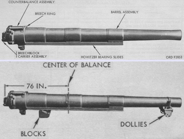
The howitzer cannon is detailed a the top, and its center of balance is noted at the bottom. The cannon consisted of a built-up or laminated barrel with a chrome-plated chamber and bore. It was aligned in its mount by longitudinal rails secured to three hoops shrunk onto the jacket. It was 204.9" (520.4cm) long, with 164.8" (418.6cm) of rifling. (Picture from TM 9-1000-218-35.)
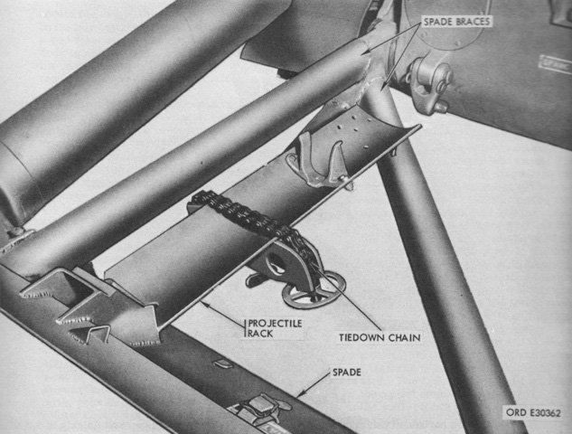
Additionally, two one-round projectile racks were installed in the braces for the recoil spade. The projectiles were held in place by the tiedown chains. (Picture from TM 9-2300-216-10.)
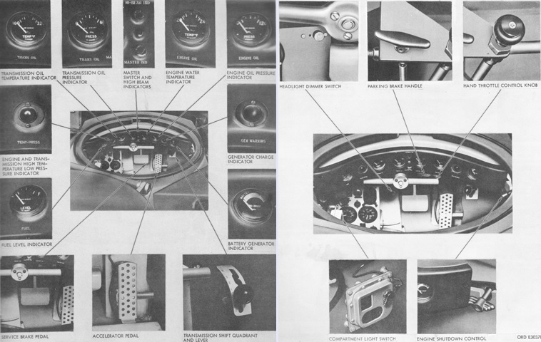
An overview of the driver's position, controls, and instruments is provided here. (Picture from TM 9-2300-216-10.)
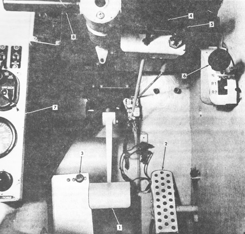
A closer view of the driver's position is seen in this picture. 1. Service brake pedal. 2. Accelerator pedal. 3. Headlight dimmer switch. 4. Parking brake handle. 5. Hand throttle control knob. 6. Transmission shift quadrant and lever controls. 7. Operator's compartment instrument and switch panel. 8. Steering bar. (Picture from TM 9-2300-216-10 C5.)
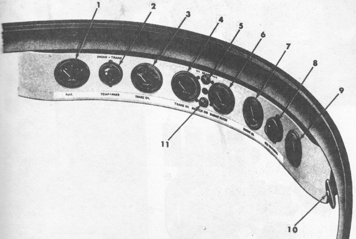
The operator's compartment indicator panel is detailed here. 1. Fuel level indicator. 2. Engine and transmission high temperature/low pressure indicator light. 3. Transmission oil temperature indicator. 4. Transmission oil pressure indicator. 5. High-beam indicator light. 6. Engine coolant temperature indicator. 7. Engine oil pressure indicator. 8. Generator charge indicator light. 9. Battery-generator indicator. 10. Engine shutdown control handle. 11. Master switch indicator light. (Picture from TM 9-2300-216-10 C5.)
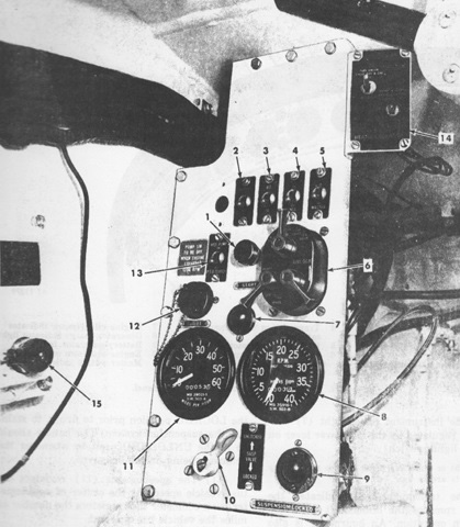
The operator's compartment instrument and switch panel is labeled in this image. 1. Starter switch. 2. Infrared receiver switch. 3. Infrared blackout (IR-BO) switch. 4. Instrument panel switch. 5. Vehicle master switch. 6. Vehicle lights switch. 7. Instrument panel light. 8. Tachometer. 9. Suspension-locked indicator light. 10. Suspension lockout valve control handle. 11. Speedometer. 12. Utility outlet. 13. Hydraulic pump power takeoff clutch switch. 14. Engine air box heater switch panel. 15. Driver's compartment light switch. (Picture from TM 9-2300-216-10 C5.)
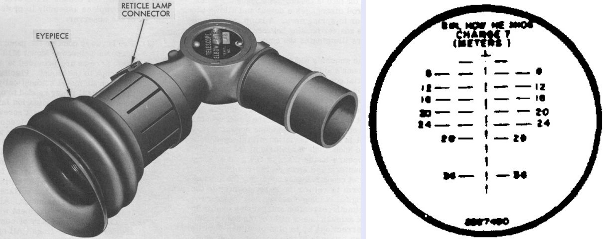
The elbow telescope M116 differed from the M116C found in the 175mm self-propelled gun M107 by having a reticle pattern calibrated for the 8" howitzer. (Picture from TM 9-2300-216-10 and TM 9-1240-288-35P.)
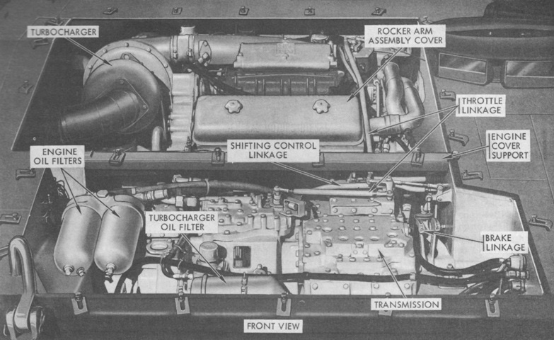
The powerplant is shown installed from the front of the vehicle. The transmission gear ratios were 4.68:1 for first (low), 3.17:1 for second, 1.58:1 for third, and 0.78:1 for fourth. Reverse 1 was 5.59:1, and reverse 2 was 3.78:1. The final drive gear ratio was 5.35:1. (Picture from TM 9-2300-216-10.)
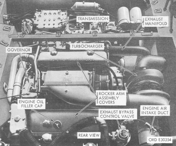
The powerplant is seen here from behind. The engine's maximum governed speed was 2,450rpm with no load and 2,300rpm under full load. It idled at 450-600rpm. (Picture from TM 9-2300-216-10.)
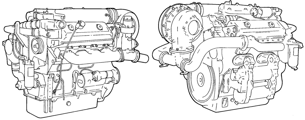
The engine is shown isolated from the left front and right rear, respectively. The Model 7083-7398 engine featured a rear-mounted T3030 turbocharger; a turbocharger regulator; a dual-range speed limiting governor; a trunk piston and connecting rod assembly through serial number 8VA-294356, or a crosshead piston and connecting rod assembly from serial number 8VA-294357 and above; the crankcase breather on the flywheel housing; Model N80 fuel injectors; front-mounted fuel filter and strainer; airbox heater fuel pump; and thermostat, housing, and water crossover tubes. Bore and stroke were 4.25" (10.8cm) and 5.0" (13cm), respectively, for a displacement of 568in³ (9.31L). The engine was 55.5" (141cm) long, 41.2" (105cm) wide, 40.8" (104cm) tall, and weighed 2,617lb (1,187kg). (Picture from TM 9-2815-202-34 C1.)
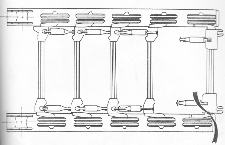
The suspension is sketched from above, with the hydraulic lockout cylinders/shock absorbers visible. Note the orientation of the idlers compared to the rest of the road wheels. (Picture from TM 9-2300-216-10 C5.)
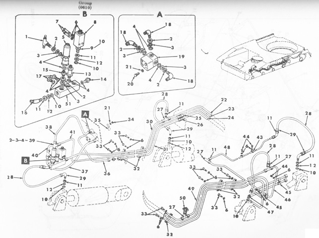
The hydraulic connections for the left-side suspension lockout cylinders/shock absorbers are sketched here. (Picture from TM 9-2300-216-20P C2.)
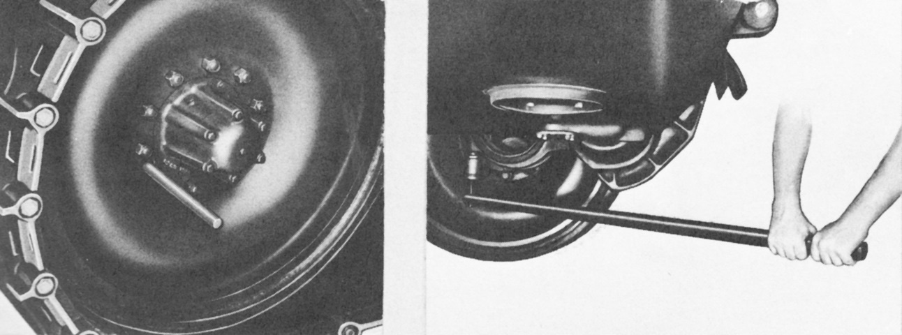
Track tension was adjusted by inserting a ⅞" (2.22cm) steel bar through the idler, locking it into the eccentric shaft spindle. The nuts on the clamping bolts were then loosened as shown on the right. (Picture from TM 9-2300-216-10.)
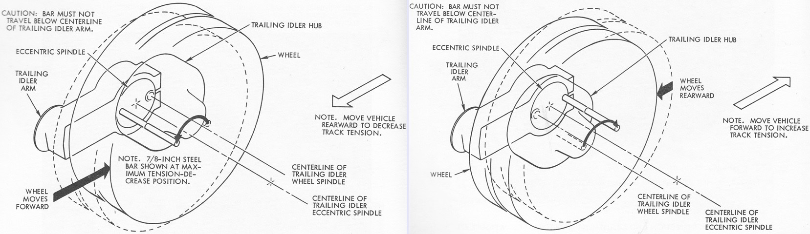
Once the preliminary steps were taken, the vehicle was slowly moved forward to increase track tension or rearward to decrease track tension. The action of the vehicle movement on the eccentric shaft spindle are shown here. (Picture from TM 9-2300-216-10.)
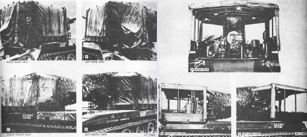
Winterization kits were developed that incorporated covers for the engine exhaust ports and the engine air intake, an engine coolant heating system, and heaters and covers for the operator's and crew compartments. The crew compartment cover is illustrated here, tied down on the left and rolled up on the right. Three dome lights were attached to the cover frame, and the crew compartment heater and ducting can be seen in the right side view of the rolled up cover. (Picture from TM 9-2300-216-10 C5.)
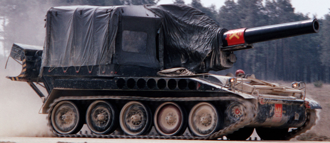
The crew compartment cover is installed and tied down on this howitzer. (Picture taken 1 Jan 1977; available from the National Archives.)
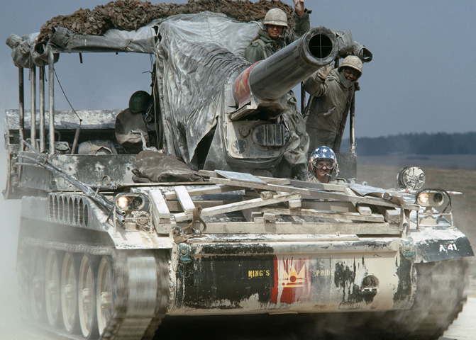
Here the cover is installed, but the sides have been rolled up and secured. (Picture taken 1 Dec 1978; available from the National Archives.)
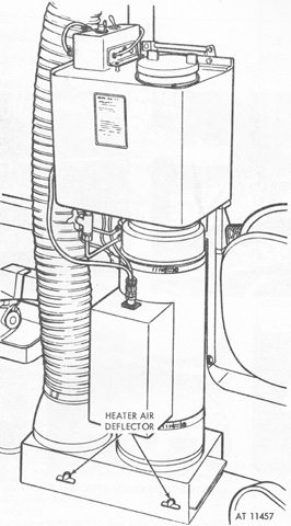
Airflow for the crew compartment heater was controlled by the air deflectors at the base. (Picture from TM 9-2300-216-10 C5.)

Parts for the driver's compartment heater are shown on the left, and his windshield and cupola assemblies are on the right. (Picture from TM 9-2300-216-20P C2.)
This side view illustrates the glaring size differences in the ordnances placed on the M110 versus the M107. The howitzer weighed ~10,240lb (~4,645kg) complete, with the breech mechanism and barrel assembly weighing ~405lb (~184kg) and ~9,835lb (~4,461kg), respectively. The mount weighed ~4,500lb (~2,040kg). (Picture available from the National Archives.)
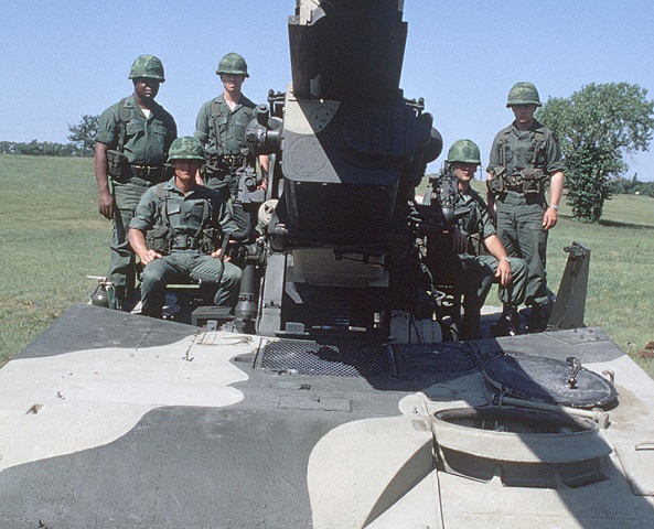
The minimalist nature of the M110's design is seen here; the vehicles have no turret or cover for anyone except the driver, whose position is visible at the bottom right of the image. The driver's periscopes are not fitted on this vehicle, however. (Picture available from the National Archives.)
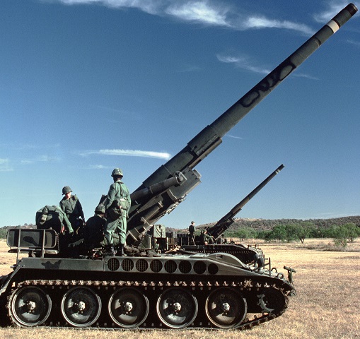
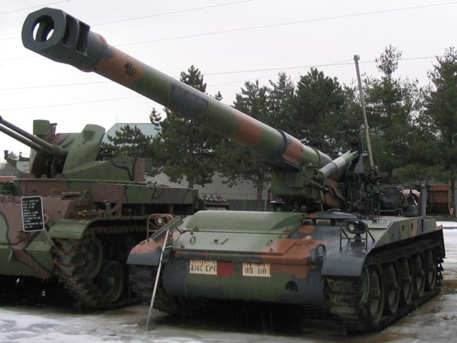
Compared to the vehicle above, the longer tube of the howitzer M201 is striking. Note that the muzzle of the tube is threaded to accept the muzzle brake which would turn the vehicle into an M110A2. The engine's circular exhaust ports can be seen in the right fender, and the hump in the hull upper front slope is there to allow room for the tall GM 8V71T diesel engine. The bench seat for the loaders above the right rear corner of the hull is folded down for use; this can be seen below the backrest. The recoil spade is also lowered for use. (Picture available from the National Archives.)
The driver is in position in this vehicle, and a stowage box is attached to the top of the recoil spade. (Picture by Anthony Edgeworth; available from the National Archives.)
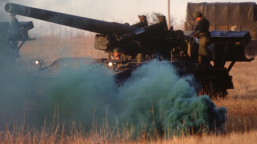
The very large double-baffle muzzle brake is an obvious identifier of the M110A2 compared to earlier vehicles.
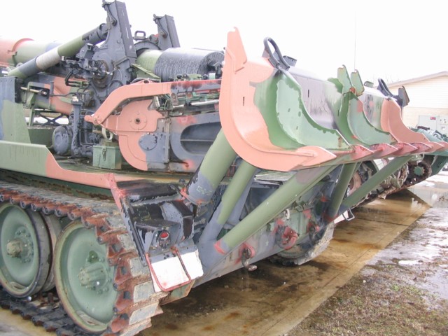
The large recoil spade is retracted on this vehicle. As above, stowage boxes and propellant charge canisters were able to be stowed on the spade for travel. The loader and rammer are folded out of the way of the spade to the howitzer breech's left.
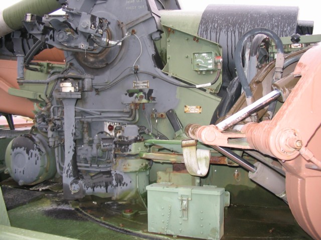
The gunner's traversing controls are visible here, as well as the folded loader and rammer.
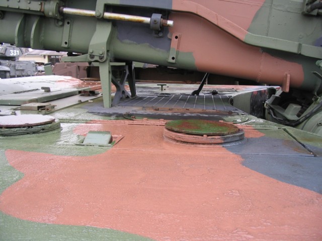
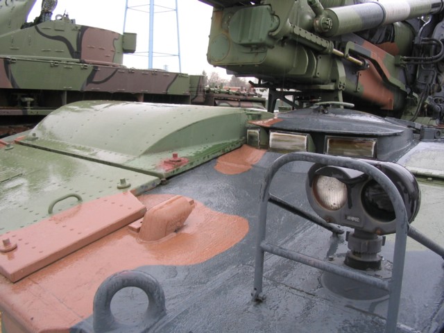
These two covers on the left side of the hull are over the battery compartment, and the cannon mount travel lock is visible in the background.
The driver was provided with three M17 periscopes for indirect vision, and the only armor on the vehicle was arranged around him.
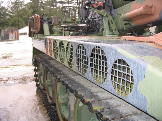
The exhaust ports for the engine were arranged along the hull's right fender. The engine's air cleaners were positioned in the opposite fender.
The gunner's elevation controls are on the right side of the ordnance.
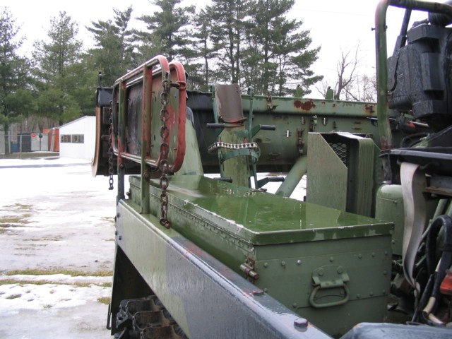
Two loaders were provided with a folding bench seat on the vehicle's right rear, seen here above a stowage box.
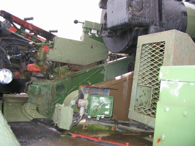
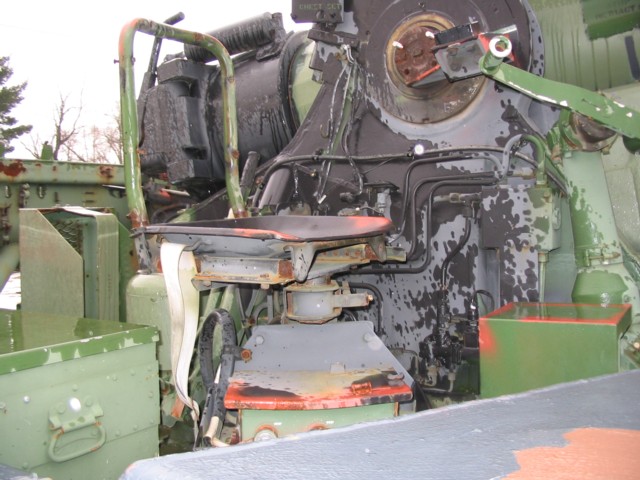
An intercom control box is visible here, as well as further details of the howitzer mount and breech.
