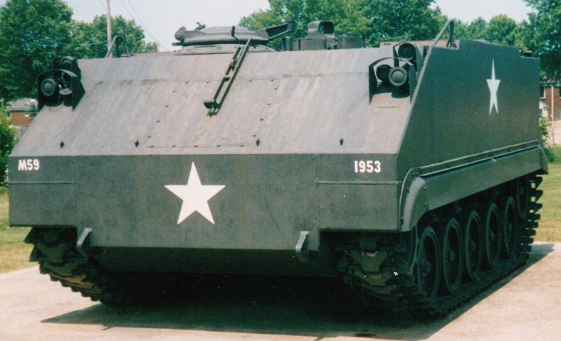
Armored Personnel Carrier M59 at the Patton Museum of Cavalry and Armor.
This early M59 is fitted with the commander's cupola featuring vision blocks and an external mount for the .50cal MG. The trim vane on the front hull is missing, but the mechanism for raising it remains. The driver's hatch is on vehicle's left side, and the prominent periscope guard on the driver's hatch is visible.
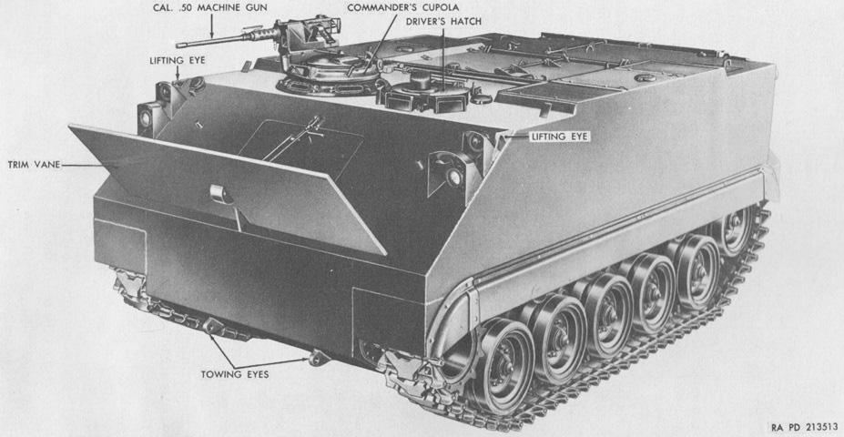
The trim vane is present on this machine, and it has been extended. (Picture from TM 9-7002 Full-track Armored Infantry Vehicle T59.)
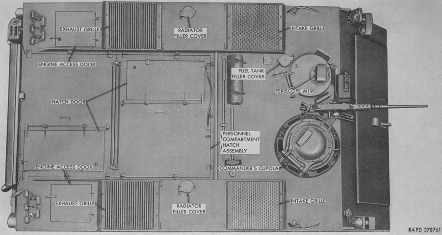
A view of the top of an early vehicle is provided here. The personnel compartment hatch assembly was bolted to the hull above the passenger compartment. (Picture from TM 9-2300-203-12.)
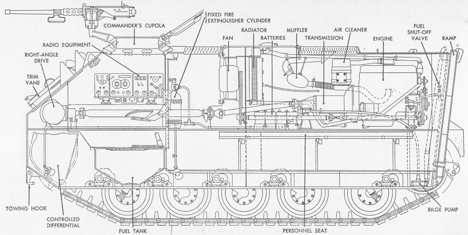
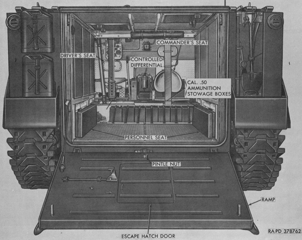
A sectionalized view of the machine is sketched in this image. (Picture from TM 9-7002 Full-track Armored Infantry Vehicle T59.)
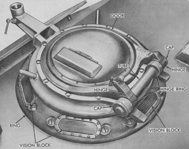
The early vision block cupola fitted to vehicles F7 through F1312 is detailed in this picture. (Picture from TM 9-2300-203-12.)
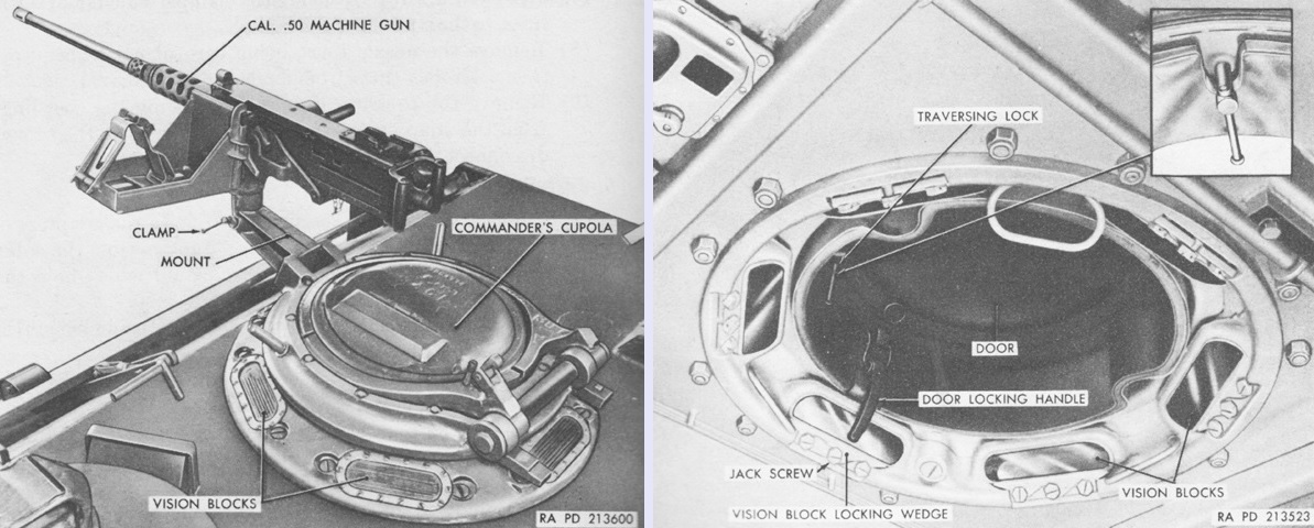
The machine gun is shown mounted on the left, and an interior view of the cupola is provided on the right. (Picture from TM 9-7002 Full-track Armored Infantry Vehicle T59.)
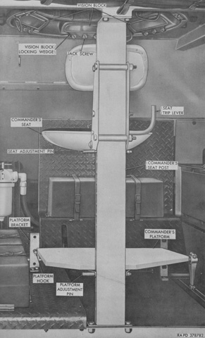
The commander's position under the early cupola is shown here. (Picture from TM 9-2300-203-12.)
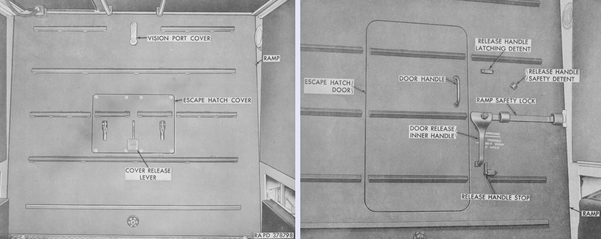
The small escape hatch fitted to vehicles F32 to F40 is seen on the left, and can be contrasted with the later larger escape hatch door on the right. When released, the escape hatch cover fell away to the outside of the vehicle. (Picture from TM 9-2300-203-12.)
The intermediate cupola fitted to vehicles F1313 through F2941 is detailed in this picture. When unlocked, the spring-loaded door of the cupolas with the external MG mount would move to the half-open position. Cupolas with periscopes featured an azimuth locking handle as opposed to the azimuth clamp screw found in earlier cupolas with vision blocks. (Picture from TM 9-2300-203-12.)
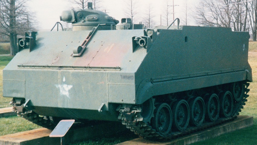
This M59 is fitted with the M13 cupola, but lacks the .50cal MG. The cupola was made from ⅜" (.953cm) armor that was sloped to present a ⅝" (1.59cm) equivalent. It weighed 816lb (370kg), and the cupola rose 12¼" (31.11cm) above the roof excluding the sight. It was 49¾" (126.4cm) long excluding the gun, and was 35" (89cm) wide while using a standard 29.75" (75.57cm) cupola deck opening. The cupola rotated on a single row of plastic ball bearings.
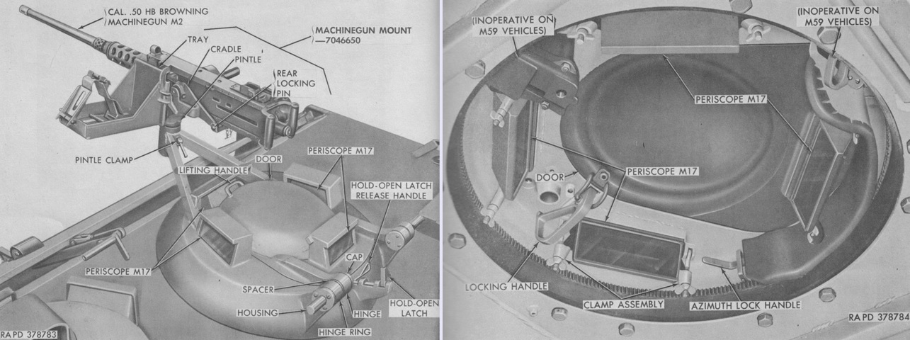
Details of the of the M13 cupola are labeled. The periscope sight M28 was shared with the M48A1 and M48A2 tanks. (Picture from TM 9-2300-203-12.)
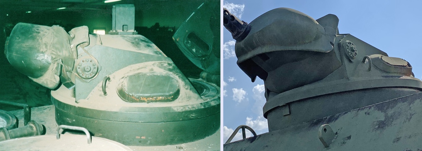
The M13 cupola is displayed from the side on the left and from below on the right. The rear clamshell-like door is open in the left image, and the vision blocks can be seen near the base of the cupola. The door automatically latched at half-open and fully-opened positions, but had to be pulled or pushed to its open or closed positions. The guard for the M28 sighting periscope sits atop the forward half of the cupola. Testing in 1958 showed that splash from .30 caliber ball ammunition could enter the cupola from above and from under the machine gun cradle with the machine gun at maximum depression and elevation, respectively, and through the cupola hatch seam. Caliber .30 armor-piercing (AP) ammunition striking the flank of the machine gun cradle could affect the machine gun elevation, and traverse could be locked by caliber .30 and caliber .50 AP striking the opening between the cupola and the cupola base ring. The cupola could be penetrated by caliber .50 AP to an equivalent range of 380 yards (350m) when struck in the direct flank above the vision blocks, and the hatch was penetrated to an equivalent range of 440 yards (400m) from 15° overhead. Caliber .50 AP was unable to penetrate the cupola roof, and caliber .30 AP was similarly unable to get through the cupola side.
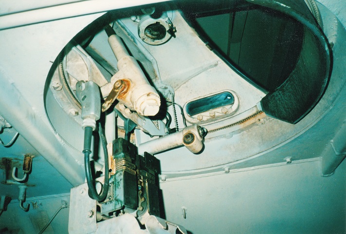
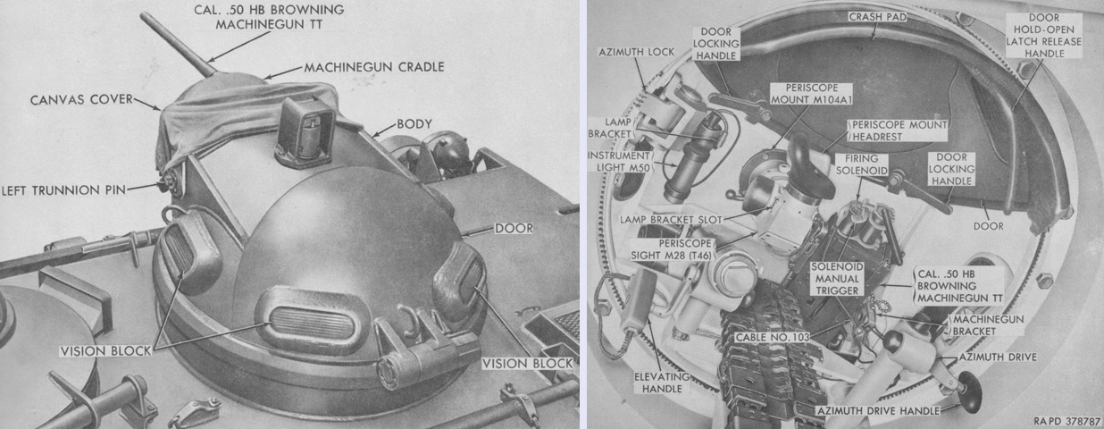
The interior of the M13 machine gun cupola is visible here. The gray-colored handle was for elevation, and to the right of this is the guide chute for the .50cal ammunition. The M104A1 mount for the M28 sighting periscope is at the crest of the cupola body, and the horizontal white shaft behind the ammunition chute is the azimuth drive. The firing switch plunger for the machine gun is atop the elevating handle.
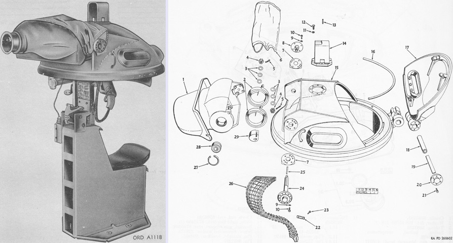
The cupola, less its slip ring assembly, is shown assembled on the left, and an exploded view is drawn on the right. 1. Cradle. 2. Spring, spiral, torsion (2). 3. Washer, flat (6). 4. Nut, slotted, hexagon (2). 5. Pin, cotter (2). 6. Cover, assembly, canvas, cupola. 7. Guide, cover retainer (2). 8. Pin, trunnion. 9. Washer, lock (10). 10. Screw, cap, hexagon head (10). 11. Washer, tab lock (4). 12. Screw, cap, hexagon head (4). 13. Pin, straight, headless. 14. Guard, assembly, sight. 15. Body, assembly. 16. Rubber strip, cellular. 17. Hatch assembly. 18. Tube. 19. Spring, flat, torsion (8). 20. Cover, assembly, hatch hinge spring. 21. Screw, cap, hexagon head (6). 22. Clip, ammunition chute. 23. Screw, machine (2). 24. Pin, trunnion. 25. Key, machine. 26. Chute, assembly, ammunition. 27. Ring, retaining (2). 28. Bearing, roller, airframe (2). 29. Anchor, spring. (Picture from TM 9-500 C3 and TM 9-1005-227-35P.)
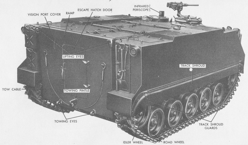
This rear view shows the larger escape hatch door in the rear ramp. The towing pintle is visible below the door, and to either side of the door are hooks for hanging a tow cable. Two five-gallon (19L) cans were stowed on the rear of the left sponson, while on the right were pioneer tools. (Picture from TM 9-7002 Full-track Armored Infantry Vehicle T59.)
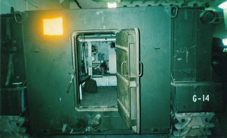
The rear door is open here, revealing its cross-section and providing a view of the interior all the way to the driver's position at the front.
The ramp is lowered in this image of a vehicle with an external machine gun mount, and the cans and pioneer tools are mounted. (Picture from TM 9-2300-203-12.)
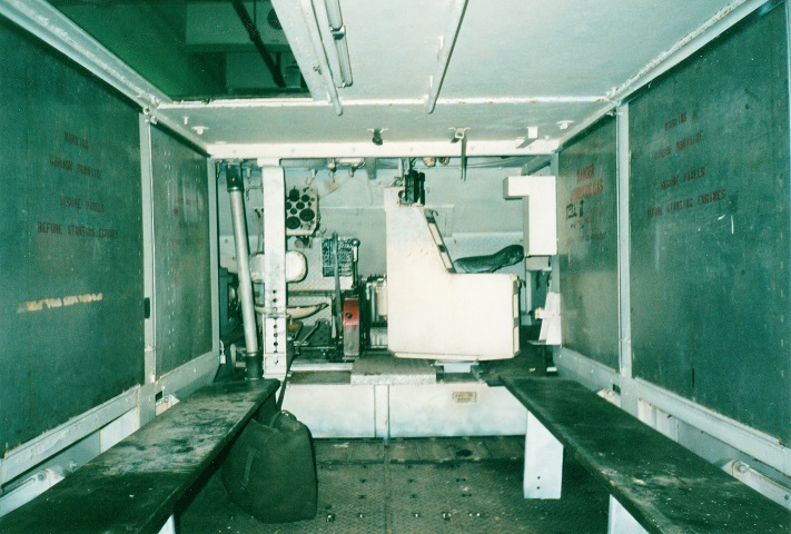
This shot is facing forward into the body of the M59. When the benches were folded out of the way, a jeep could be driven into the passenger compartment. The drivetrain for the vehicle occupied the side sponsons, and left room in the passenger compartment for easy entry into and exit from the APC. The commander's seat is to the front right, and is facing towards the driver in this view. The commander's seat rotated with the machine gun in vehicles fitted with the M13 cupola. A spare M28 sighting periscope was stored in the upside-down L-shaped compartment to the right of the commander's station.
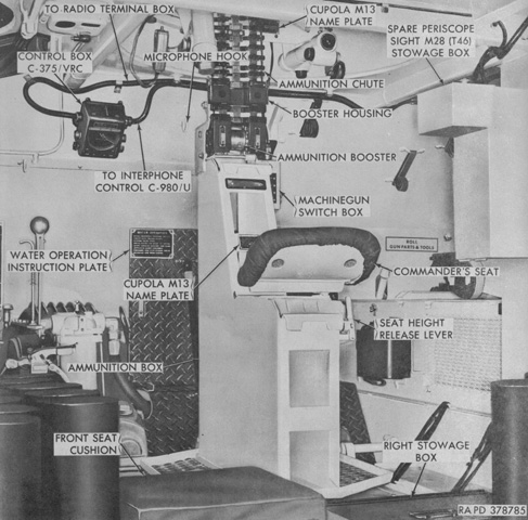
Under the M13 cupola, the commander sat astride the machine gun ammunition supply and feed. The ammunition box held 735 linked rounds, and fed ammunition through the chute up to the machine gun. (Picture from TM 9-2300-203-12.)
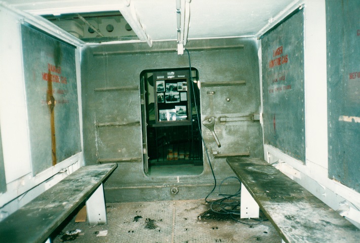
Another interior view provides a look to the rear of the vehicle. The open escape hatch door and and open roof hatch are visible, as are the handrails running along the vehicle ceiling. The door release inner handle is to the right of the escape hatch door, and just to the right of this is the rear ramp safety lock. The latches above and to the right of the release handle are latching and safety detents.
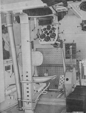
The driver was seated to the vehicle's front left, and his position is illustrated here. A. Cover latch handle. B. Choke control knob. C. Ramp lock handle. D. Dome light. E. Periscope M17. F. Control box C-375/VRC. G. Instrument panel. H. Right steering brake lever. J. Shifting lever. K. Driver's instruction plate. L. Shifting control housing. M. Right auxiliary shifting lever. N. Left auxiliary shifting lever. P. Accelerator pedal. Q. Driver's seat. R. Ramp hydraulic cylinder. S. Vehicle name plate. T. Vehicle data plate. U. Fuel tank filler pipe. V. Left steering brake lever. W. Throttle control knob. X. Dimmer switch. (Picture from TM 9-2300-203-12.)
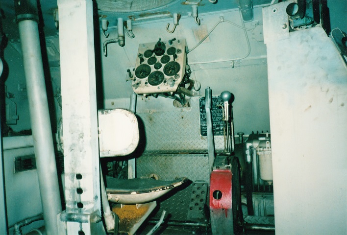
An actual view of the driver's position is presented here.
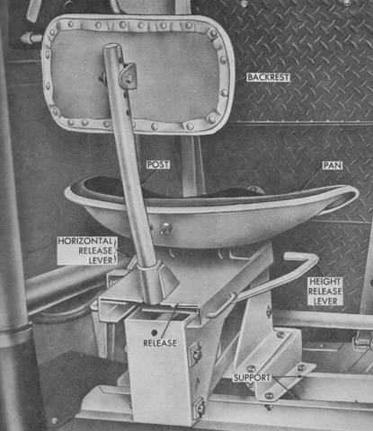
Vehicles F7 through F786 were fitted with the driver's seat shown above. (Picture from TM 9-2300-203-12.)
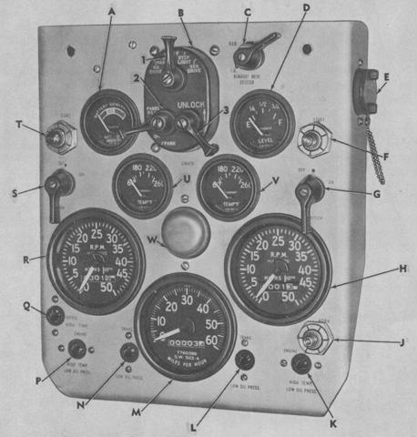
The driver's instrument panel is labeled in this image. A. Battery-generator indicator. B. Main light selector switch. 1. Main light switch lever. 2. Panel light switch lever. 3. Release lever. C. Blackout drive selector switch. D. Fuel gage. E. Accessory outlet socket. F. Right starting switch. G. Right ignition switch. H. Right tachometer-hourmeter. J. Horn switch. K. Right engine high temperature-low oil pressure warning light. L. Right transmission low oil pressure warning light. M. Speedometer-odometer. N. Left transmission low oil pressure warning light. P. Left engine high temperature-low oil pressure warning light. Q. Differential high temperature warning light. R. Left tachometer-hourmeter. S. Left ignition switch. T. Left starting switch. U. Left water temperature gage. V. Right water temperature gage. W. Panel light. (Picture from TM 9-2300-203-12.)
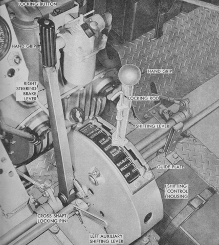
The center position of the shifting lever was NEUTRAL. The forward quadrants of the shifting lever engaged LOW ranges, while the rearward quadrants engaged HIGH ranges. Both LOW and HIGH ranges had DRIVE, HILLY, and REV positions. LOW and HIGH were the different output gear ratios provided by the controlled differential. The locking rod needed to be pulled upwards before the shifter could be changed into reverse. The auxiliary shifting levers allowed the transmissions to be engaged without the controlled differential, permitting the drive shafts to spin and provide power for the ramp hydraulic system without moving the vehicle. Typically the levers were interconnected, and raising the levers after the shifting lever was placed in NEUTRAL engaged the transmissions. (Picture from TM 9-2300-203-12.)
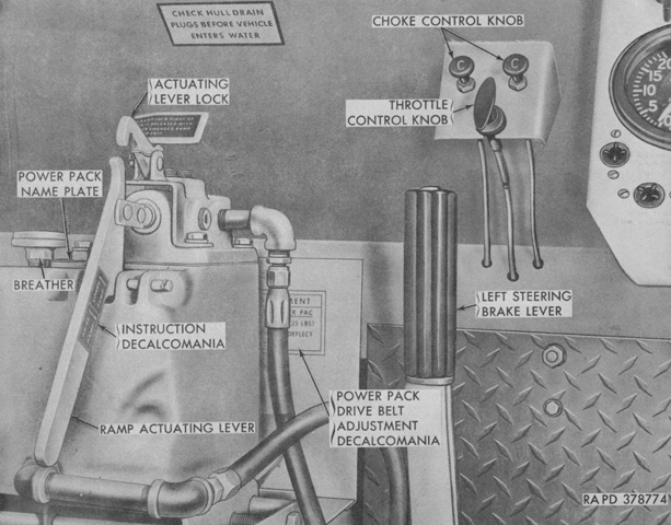
The choke control knobs, one for each engine, could be pulled outwards to choke the carburetors when starting in freezing temperatures. The throttle control knob was pulled outward to increase the idle speed without using the accelerator pedal. It locked into whatever position it was pulled, and was released by a half-turn and pushing it forward. The ramp actuating lever was pulled up to lower the ramp and pushed down to raise the ramp. Ramp speed depended on the amount of force applied to the lever, and it automatically returned to a neutral position when released. The actuating lever lock could be used to lock the lever into position to quickly lower the ramp in emergencies. (Picture from TM 9-2300-203-12.)
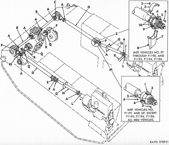
The power train is diagrammed here. A. Universal joint. B. Differential input propeller shaft. C. Right-angle drive output shaft. D. Front propeller shaft. E. Front propeller shaft bearing (M59 vehicle No. F7-F1190, F1193, F1194, and F1196) 1. ⅜-inch (.95-cm) self-locking nut. 2. Upper dust shield. 3. No. 10 assembled washer screw. 4. Mounting plates. 5. Bearing housing. 6. ⅜ x 1¼ cap screw. 7. Lower dust shield. 8. No. 10 self-locking nut. 9. Vibration insulator. 10. Grease seal. F. Front propeller shaft yoke. G. Split collar. H. Rear propeller shaft. J. Bilge pump drive pulley. K. Bilge pump drive belt. L. Transmission output yoke. M. Front propeller shaft bearing (M59 vehicles Nos. F1191 and up except F1193, F1194, and F1196, all M84 vehicles) 1. Mounting plates. 2. Bearing housing. 3. ⅜ x 1¼ cap screw. 4. Vibration insulator. 5. Grease seal. 6. ⅜-inch (.95-cm) self-locking nut. N. Ramp hydraulic power pack drive belt. P. Final drive yoke. Q. Universal joint. R. Differential output propeller shaft. (Picture from TM 9-2300-203-12.)
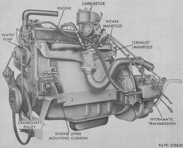
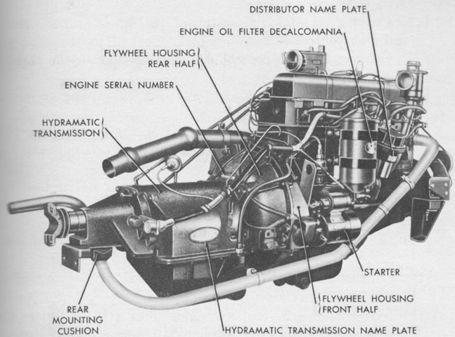
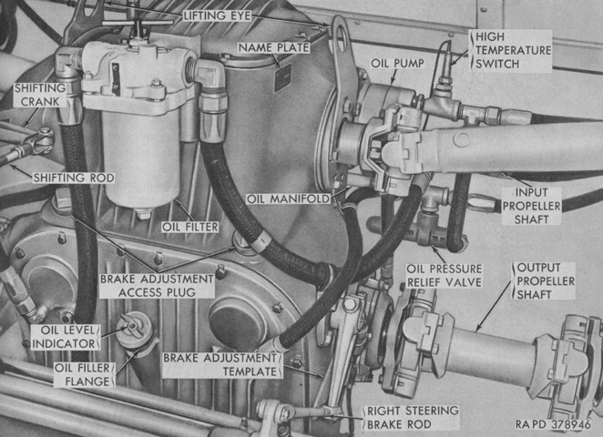
An engine and transmission are seen here. The GMC 302 was a valve-in-head water cooled engine, and bore and stroke were each 4" (10cm) for a displacement of 301.6in³ (4.942L). Firing order was 1-5-3-6-2-4, and the no-load and full load governed speeds were 3,600rpm and 3,400rpm, respectively. Idle speed was 500-550rpm. (Picture from TM 9-2300-203-12.)
An opposite view of a powerplant is provided in this image. The front of the engine was considered the water pump end, and faced the rear when mounted in the vehicle. The right and left sides of an engine were determined by looking at the engine from its rear (i.e., from the vehicle's front). (Picture from TM 9-7002 Full-track Armored Infantry Vehicle T59.)
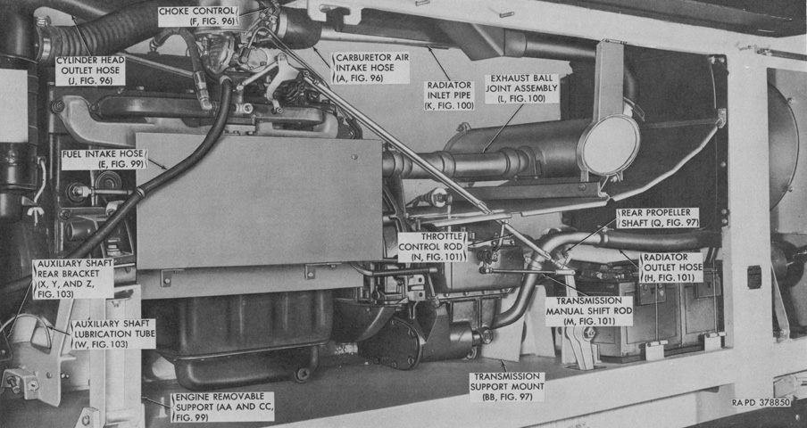
The left-side engine and transmission are shown installed in the sponson. Note the storage batteries under the radiator outlet hose. (Picture from TM 9-2300-203-12.)
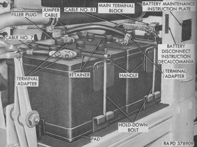
Two 12-volt 6TN type batteries were connected in series to provide a 24-volt electrical supply. They were housed on a pad at the front of the left powerplant compartment. (Picture from TM 9-2300-203-12.)
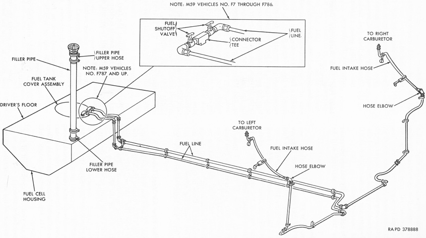
A schematic of the fuel system is sketched here. The fuel tank assembly was a synthetic rubber fuel cell suspended within a fuel cell housing enclosed by the driver's floor. (Picture from TM 9-2300-203-12.)
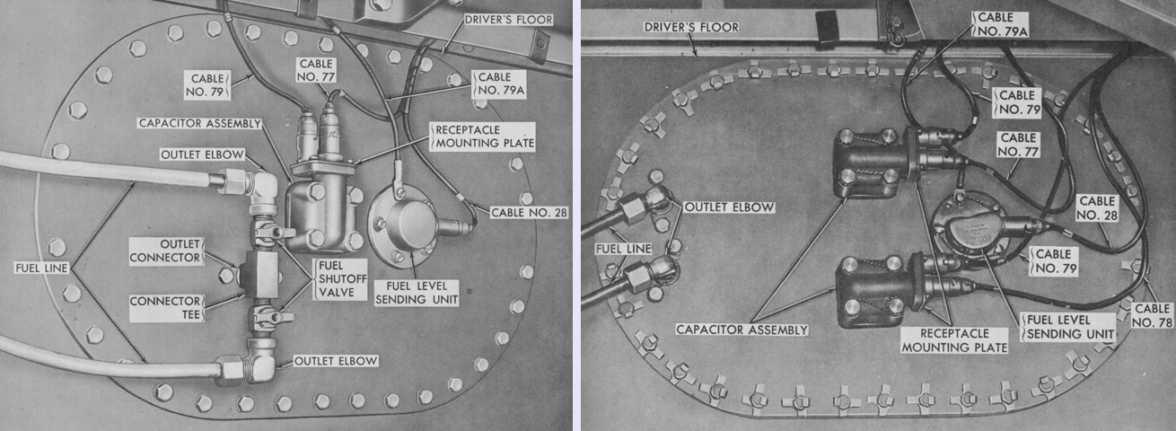
The fuel pumps, fuel level sending unit, fuel level float, and radio interference capacitor assemblies were found on the fuel tank cover assembly. Vehicles F7 through F786 were made with the fuel tank cover assembly seen on the left, while vehicles F787 and above as well as 4.2" self-propelled mortars M84 were constructed with the cover assembly on the right. (Picture from TM 9-2300-203-12.)
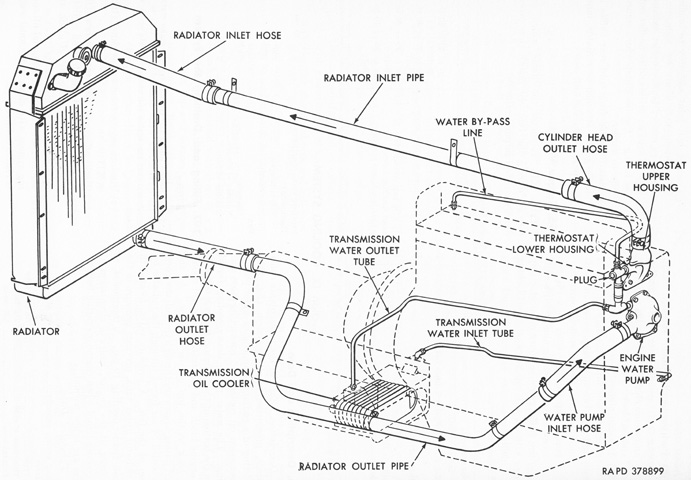
The cooling liquid circuit is shown in this sketch; each engine had its own cooling system. Twenty-eight quarts (26L) of coolant was used. (Picture from TM 9-2300-203-12.)
The controlled differential received power from the input propeller shafts, and a transfer unit synchronizer on the transfer shaft transmitted the power through the HIGH (1:1.092) or LOW (2.359:1) range constant-mesh gears to the controlled differential steering assembly below. Brake drums on the output propeller shafts of the steering assembly slowed their respective output shafts, while the differential increased the speed of the opposite output propeller shaft by an equal amount and thereby turned the vehicle. Actuating both steering brake levers equally slowed or stopped the vehicle. (Picture from TM 9-2300-203-12.)
A partially exploded view of the controlled differential is provided in this image. (Picture from ORD 9 SNL G-280 List of All Service Parts of Infantry Vehicle, Armored, Tracked, M59 (T59).)
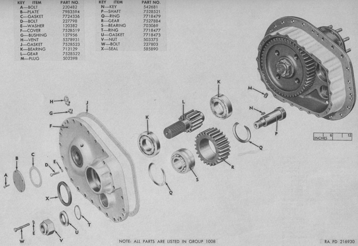
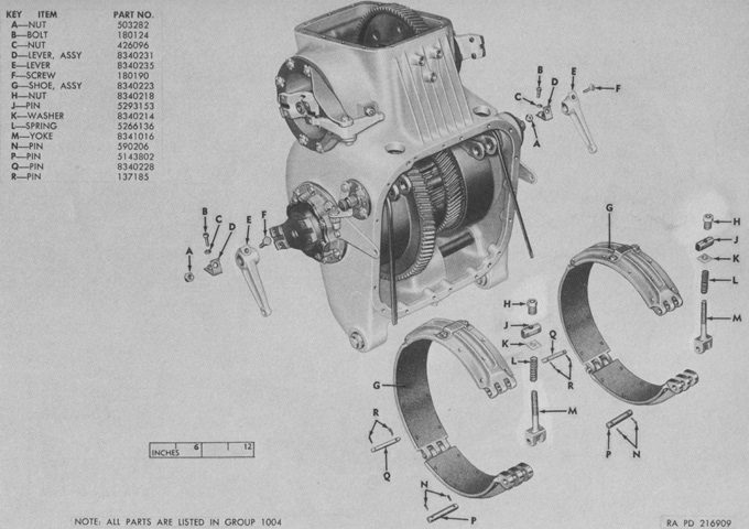
Details of the innards of the left final drive gearbox assembly can be seen here. (Picture from ORD 9 SNL G-280 List of All Service Parts of Infantry Vehicle, Armored, Tracked, M59 (T59).)
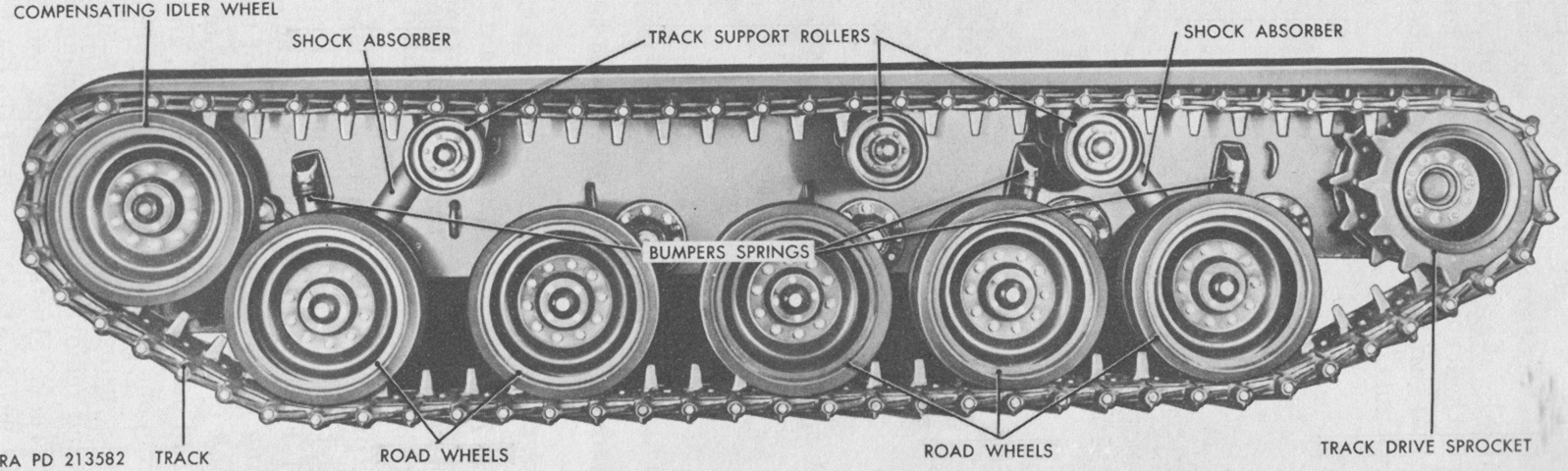
Suspension nomenclature is given here. (Picture from TM 9-7002 Full-track Armored Infantry Vehicle T59.)
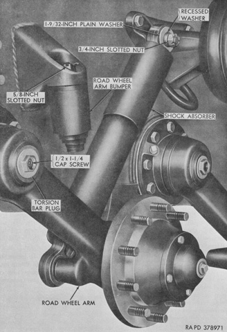
Further details of the suspension can be gleaned with the road wheels removed. (Picture from TM 9-2300-203-12.)
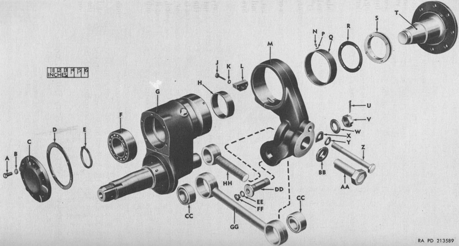
An exploded view of the compensating idler wheel arm, spindle, and link is diagrammed here. The idler was mounted on an eccentric spindle and connected to the rear road wheel via a link. When the rear road wheels passed over obstacles, the idlers were moved to the rear by the links, ensuring the track tension remained correct. A. Bolt. B. Lock washer. C. Cover. D. Cover gasket. E. Retaining ring. F. Ball bearing. G. Compensating idler wheel arm. H. Bushing-type bearing. J. Bolt. K. Washer. L. Threaded plate. M. Track tension adjusting arm. N. Bolt. P. Washer. Q. Guard. R. Oil seal gasket. S. Oil seal. T. Spindle. U. 1⅝" (4.128cm) cotter pin. V. Nut. W. 2½" (6.4cm) OD washer. X. Lock plate. Y. Washer. Z. Clamping bolt. AA. Track tension adjusting nut. BB. Seat. CC. Bearing. DD. Compensating idler wheel link rear bolt. EE. Washer. FF. Cap screw. GG. Compensating idler wheel link. HH. Track tension adjusting bolt. (Picture from TM 9-7002 Full-track Armored Infantry Vehicle T59.)
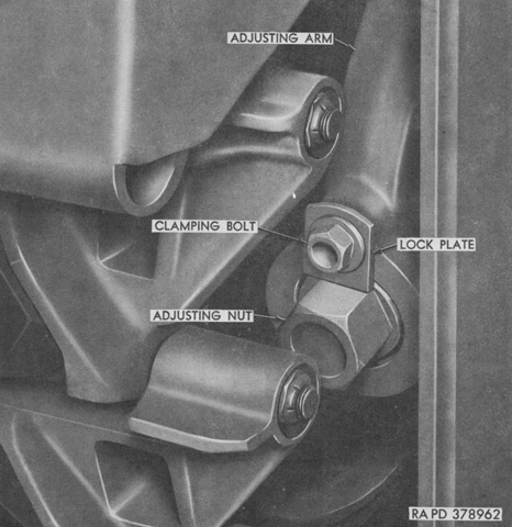
In order to adjust track tension, the clamping bolt was loosened until the lock plate could be rotated out of the way of the adjusting nut. The adjusting nut could then be loosened or tightened to move the idler wheel in or out, decreasing or increasing tension, respectively. (Picture from TM 9-2300-203-12.)
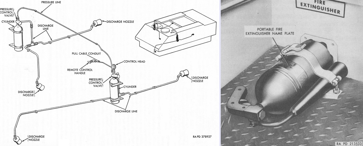
The fixed fire extinguisher system (left) was composed of a 10lb (4.5kg) CO2 cylinder mounted in each engine fan compartment, which were routed to two discharge nozzles apiece. One nozzle from each cylinder was mounted at the front of its respective engine compartment, one nozzle was forward of the driver's compartment, and the final nozzle was under the floor panel at the right front of the personnel compartment. A remote control handle that discharged both cylinders was installed behind the driver's seat. In an emergency if the remote control failed, the left-side fan access panel was to be removed, and the control head on that cylinder could then be reached. In addition, a portable 5lb (2.3kg) extinguisher (right) was mounted behind the driver's seat. (Pictures from TM 9-2300-203-12 and TM 9-7002 Full-track Armored Infantry Vehicle T59.)
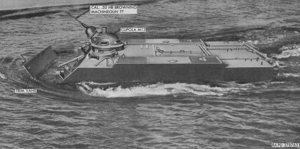
The freeboard of a swimming machine can be seen here. Note the extended trim vane to prevent water from swamping the front of the vehicle. (Picture from TM 9-2300-203-12.)
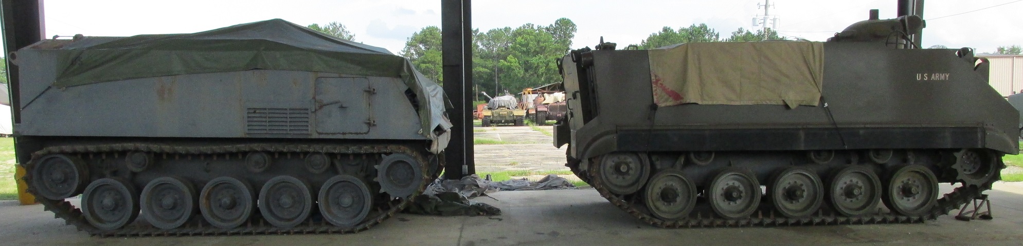
An interesting comparison between the outgoing M75 and its replacement can be made here.
