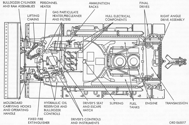
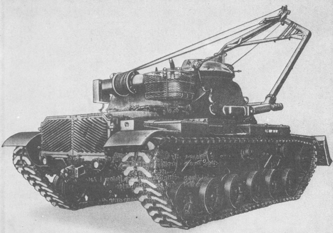
Combat Engineer Vehicle M728.
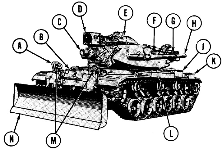
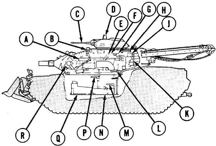
The stubby 165mm gun, crane boom on the turret, and dozer blade are striking features of the M728. A. Brush guard, headlight. B. Personnel heater exhaust outlet. C. 165-mm gun tube. D. Searchlight. E. M19 commander's cupola. F. Hook, winch cable. G. Boom travel lock. H. Boom. J. Engine air cleaner. K. Rear fender stowage box. L. Front fender stowage box. M. Headlight. N. Moldboard. (Picture from TM 9-2350-222-10-1 C6.)
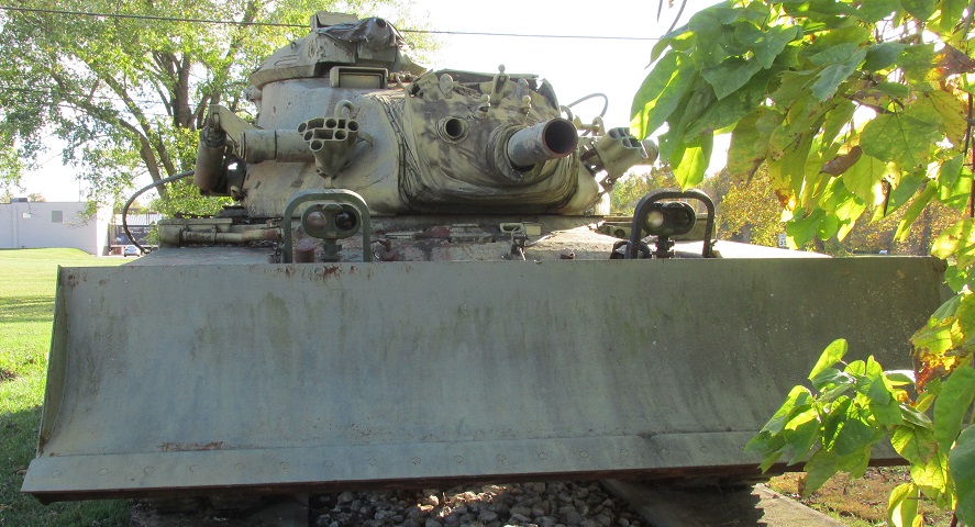
The headlight clusters and their brush guards have been extended to clear the dozer blade. The gunner's telescope M105F would peer through the aperture visible of this side of the gun shield.
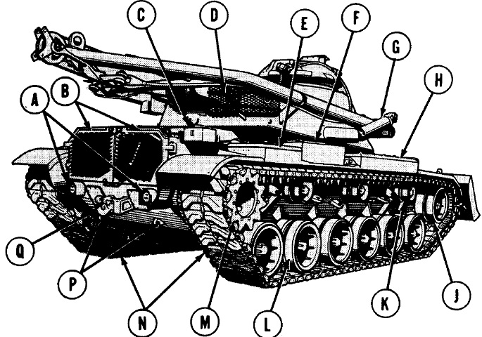
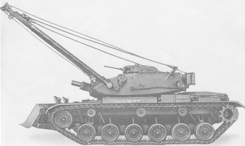
The crane boom extended over the rear deck when stowed. A. Taillight. B. Rear grille doors. C. External handset box. D. Bustle rack, stowage. E. Rear fender stowage box. F. Engine air cleaner. G. Boom linear actuating cylinder. H. Front fender stowage box. J. Compensating idler wheel. K. Track support roller. L. Roadwheel and hub. M. Drive sprocket. N. Track. P. Tow eye. Q. Tow pintle. (Picture from TM 9-2350-222-10-1 C6.)
A similar angle to the above diagram is shown of an actual machine.
Some internal components are sketched here. A. 7.62-mm machine gun. B. Gunner's periscope. C. Caliber .50 machine gun barrel. D. Commander's periscope. E. Commander's gun elevating and turret traversing control. F. Winch control. G. Boom control. H. Commander's observation seat. J. Radio equipment. K. Ammunition stowage rack. L. Commander's seat. M. Commander's platform. N. Portable fire extinguisher. P. Gunner's seat. Q. Turret platform. R. M150 gun mount. (Picture from TM 9-2350-222-10-1 C6.)
The top of the vehicle is shown here. A. Driver's hatch. B. Driver's vision block. C. Searchlight mount. D. Gunner's telescope port. E. Personnel heater exhaust outlet. F. Smoke grenade launchers (late model). G. Gunner's periscope. H. Cupola vision block. J. Commander's hatch. K. Smoke grenade stowage boxes (late model). L. Winch gearshift lever. M. Turret ventilating blower cover. N. Bustle rack, stowage. P. Winch. Q. Boom stayline. R. Winch cable. S. Antenna mount. T. Loader's hatch. U. Loader's periscope cover. V. Searchlight power receptacle. W. Snatch block. X. 7.62-mm machine gun port. Y. Moldboard locking hook handle. Z. Fire extinguisher release handles. AA. Lifting chain. (Picture from TM 9-2350-222-10-1 C6.)
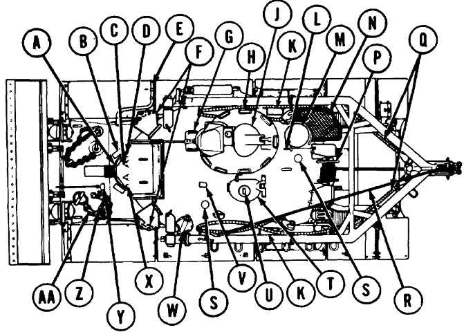
A top-down view of the hull interior is labeled in this sketch. (Picture from TM 9-2350-222-10 C2.)
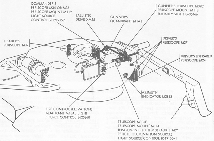
The crew's sighting and fire control instruments are diagrammed here. Note that a rangefinder was not present in the turret. (Picture from TM 9-2350-222-10 C2.)
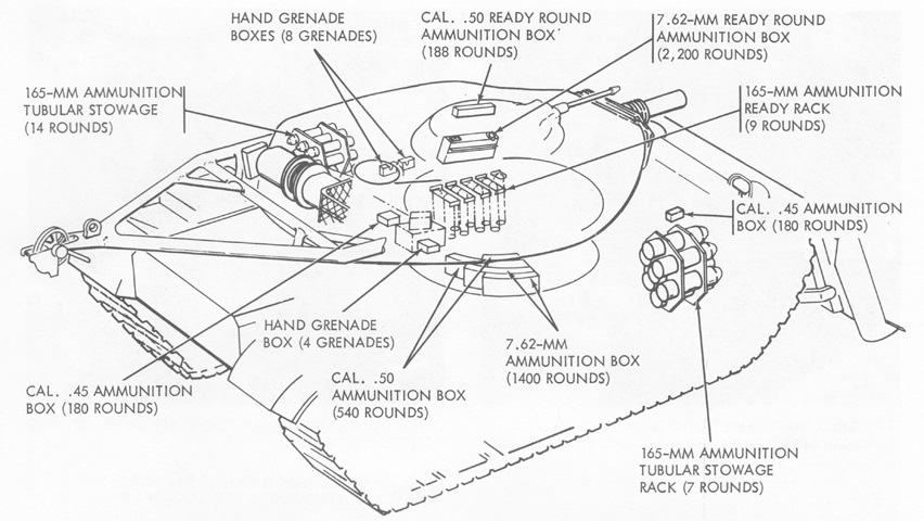
Ammunition stowage is detailed in this drawing. (Picture from TM 9-2350-222-10 C2.)
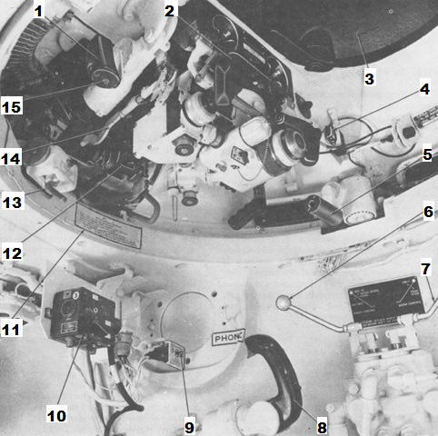
The commander's position and cupola are labeled in this image. Note the blanked-off aperture in the turret wall near the "PHONE" decal where the coincidence rangefinder would be present on a 105mm gun tank. 1. Elevating handle. 2. Periscope M36 and mount M119. 3. Cupola hatch. 4. Gun firing safety switch. 5. Traversing handle. 6. Winch control lever. 7. Boom control lever. 8. Commander's power control handle. 9. Cupola power switch. 10. Interphone and control box. 11. Warning decal. 12. Caliber .50 machine gun. 13. Azimuth lock and interlock. 14. Link assembly. 15. Gun firing trigger (switch). (Picture from TM 9-2350-222-10 C2.)
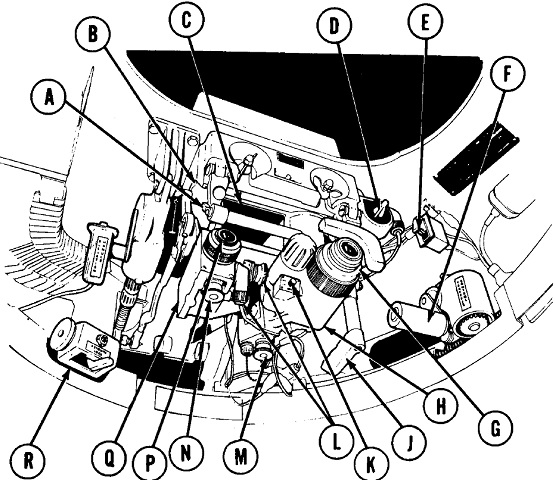
A. Headrest adjust lever. B. M36 periscope. C. Unity power window. D. Light source control. E. Gun electrical safety switch (early model). F. Cupola traversing control handle. G. IR body diopter ring. H. IR body. J. Ballistic shield control. K. IR switch. L. IR body and daylight body deflection knobs. M. IR body elevation knob. N. Daylight body elevation knob. P. Daylight body diopter ring. Q. Daylight body. R. Cupola azimuth lock and interlock. (Picture from TM 9-2350-222-10-1 C6.)
The commander's cupola periscope M34 is shown disassembled on the left with its reticle picture on the right. The M34 had a unity window with a 68° horizontal and 28° vertical field of view at zero elevation, and a 7x binocular system with a 10° field of view. It had a line of sight travel from +60° to -20°.
1. Head assembly locating keys. 2. Locking wing nuts. 3. Body assembly locating pin and pad. 4. Hook. 5. Unity power window. 6. Diopter scales. 7. Deflection boresight knob. 8. Right hand elbow assembly. 9. Elevation boresight knob. 10. Left hand elbow assembly. 11. Interpupillary scale and index mark. 12. Interpupillary knob. 13. Latch (open). 14. Binocular body assembly. 15. Hook. 16. Elevation arm assembly. 17. Head assembly. 18. Valve assembly. (Picture from TM 9-2350-222-10 C2.)
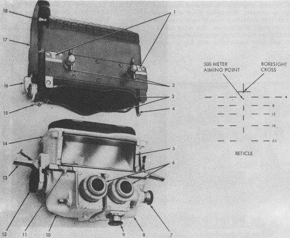
The periscope M34 was usurped by the infrared periscope M36, which could be used for daytime or night sighting. The daylight reticle is sketched in the center, and the infrared reticle is on the right. The M36's unity window provided a 60° horizontal and 28° vertical field of view at zero elevation, while the visible light channel was 7x magnification with a 10° field of view, and the infrared channel was 8x magnification with an 8° field of view. Its line of sight travel was the same as that of the periscope M34.
1. Head assembly. 2. Locking wing nuts. 3. Infrared body latch. 4. Hook. 5. Eyelens focusing ring (diopter ring). 6. Eyepiece focusing ring (green). 7. Power pack cap. 8. Infrared elbow assembly. 9. Infrared power switch. 10. Deflection boresight knob. 11. IR elevation boresight knob. 12. Infrared reticle projector. 13. Reticle light connector. 14. IR deflection boresight knob. 15. Elevation boresight knob. 16. Seven power elbow assembly. 17. Infrared reticle light connector. 18. Infrared image tube power connector. 19. Daylight body assembly. 20. Latch. 21. Hook. 22. Elevation arm assembly. 23. Valve assembly. (Picture from TM 9-2350-222-10 C2.)
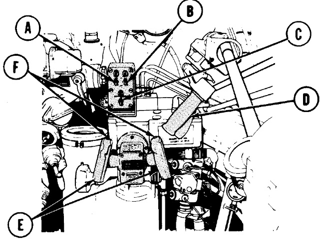
Note the smoke grenade controls present at this commander's position. A. Intercom control box. B. Searchlight remote control box. C. Commander's control handle. D. Cupola power switch. E. Grenade launcher switch. F. Grenade power switch.
The control handle allowed the commander to override the gunner's inputs when in power mode. With the smoke grenade system powered on, pressing one of the grenade launcher switches would fire 3 grenades from each discharger. Pressing both switches fired all the grenades. (Picture from TM 9-2350-222-10-1 C6.)
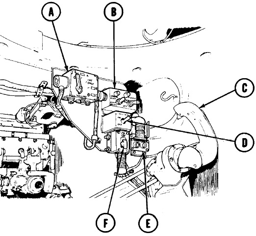
The rear of the commander's position is shown here. A. Receiver-transmitter. B. Audio frequency amplifier AM 1780/VRC. C. Observation seat lock handle. D. Domelight switch. E. Blower switch. F. Gas particulate air heater switch. G. Battle override switch.
The battle override switch restored communications power if the circuit breaker opened during battle. (Picture from TM 9-2350-222-10-1 C6.)
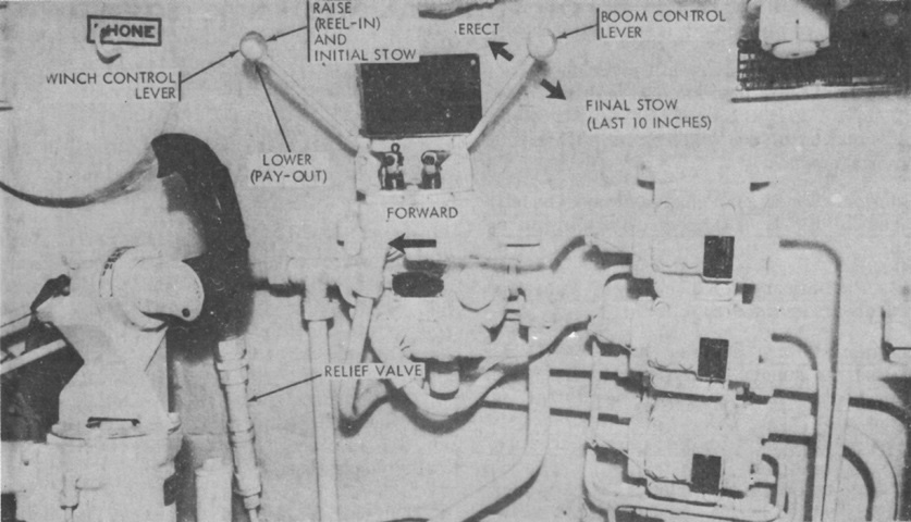
Winch and boom control levers were mounted to the commander's right. (Picture from TM 9-2350-222-10 C2.)
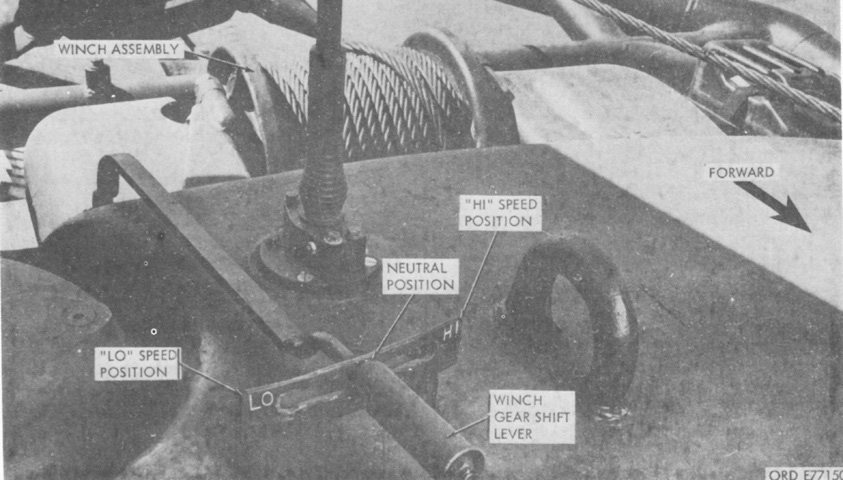
The winch gear shift lever on the turret rear had three positions: LO, NEUTRAL, and HI. Neutral disengaged the winch from the hydraulic motor, while LO and HI engaged their respective gear ranges. (Picture from TM 9-2350-222-10 C2.)
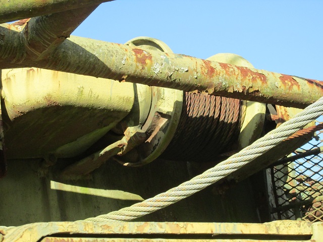
The hydraulic winch operated from the commander's station is isolated in this image.
The gunner's controls are sketched here. A. Main gun switch. B. Machine gun switch. C. Elevation/traverse power switch. D. Manual traverse handle. E. Gunner's power control handles. F. Firing triggers. (Picture from TM 9-2350-222-10-1 C6.)
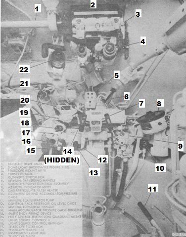
A broader view of the gunner's position is given here. 1. Ballistic drive XM15. 2. Dome light (hidden). 3. Periscope mount M118. 4. Periscope M32C. 5. Gunner's switch box. 6. Manual traversing handle. 7. Gunner's power control assembly. 8. Azimuth indicator M28E2. 9. Gas particulate filter heater. 10. Equilibrator and accumulator pressure gage. 11. Manual equilibrator pump. 12. Control pack reservoir oil level gage. 13. Manual elevating handle. 14. Main accumulator pressure gage (hidden). 15. Emergency firing device. 16. Fire control (elevation) quadrant M13A3. 17. Light source control B. 18. Light source control 8619165-1. 19. Telescope filter box. 20. Telescope mount M114. 21. Instrument light M50. 21. Telescope M105F. (Picture from TM 9-2350-222-10 C2.)
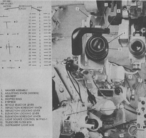
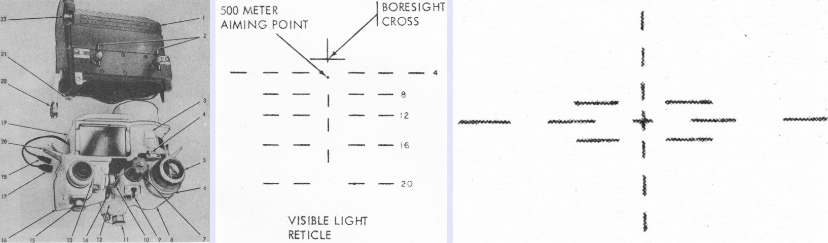
The gunner's telescope M105F was the primary direct sight for the 165mm gun. It was an 8x magnification device with a 7°30' field of view. Two reticles could be used, one graduated in meters (shown on the left) and one graduated in mils (shown on the right). (Picture from TM 9-2350-222-10 C2.)
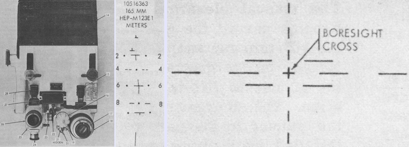
The infrared periscope M32C was coupled to the ballistic drive XM15, and was the gunner's secondary direct sight for the 165mm gun and primary direct sight for the coaxial machine gun. Its unity window provided a 30°32' horizontal and 5°48' vertical field of view, and the infinity sight 8635466 was installed behind the unity window to project a 20-mil illuminated circle onto the unity window for use during coaxial machine gun engagements. The daylight and infrared 165mm reticles are drawn in the center and at the right, respectively.
14. Head assembly. 15. Body latches (IR). 16. Power pack cap. 17. Diopter ring (IR). 18. Focusing ring. 19. IR body. 20. IR power switch. 21. Deflection boresight knob (daylight). 22. Elevation boresight knob (IR) (hidden). 23. Deflection boresight knob (IR). 24. Elevation boresight knob (daylight). 25. Daylight body. 26. Diopter ring (daylight). 27. Unity power window. 28. Body latches (daylight). (Picture from TM 9-2350-222-10 C2.)
This is the breech of the 165mm gun M135. The cradle and port for the coaxial machine gun are visible to the main gun's left, but the machine gun is not mounted in this drawing. Before loading, the breech was opened by the breech operating handle. After the round was chambered, the breech was closed by smartly raising the release lever. A. Breech operating handle. B. Plunger to release breech operating handle. C. Release lever. (Picture from TM 9-2350-222-10-1 C6.)
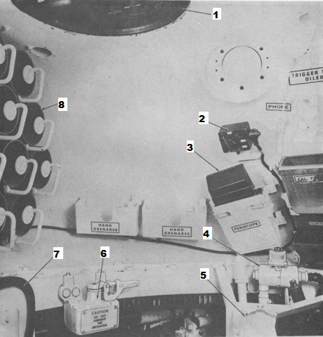
The loader's spot is shown in this image; note the blanked-off aperture for the omitted rangefinder near the top right. 1. Loader's hatch. 2. Interphone and control box. 3. Periscope M37. 4. Gas particulate filter heater. 5. Ammunition ready racks. 6. Turret lock. 7. Loader's seat. 8. Ammunition stowage tubes. (Picture from TM 9-2350-222-10 C2.)
9. Replenisher indicator tape. 10. Dome light. 11. 7.62-mm machine gun M73. 12. Main gun safety switch. 13. Breech operating handle. 14. Breechblock release lever. 15. Deflector plate. 16. Spent cartridge case bag. 17. Shell ejection shield. (Picture from TM 9-2350-222-10 C2.)
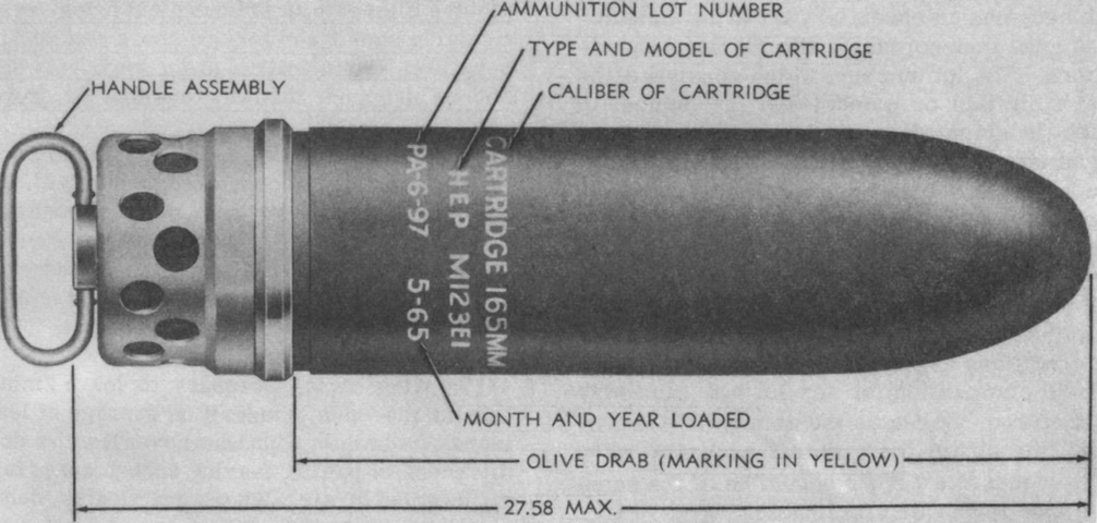
High-explosive plastic M123E1 cartridges were used with the 165mm gun. The projectile as fired weighed 62.5lb (28.4kg), and the complete round weighed 65.6lb (29.8kg). A folding lifting handle was provided to ease loading. A latch secured the lifting handle to the ammunition case, and after the round was chambered this latch was lifted and the handle was rotated until it was freed. The breech could then be closed. (Picture from TM 9-2350-222-10 C2.)
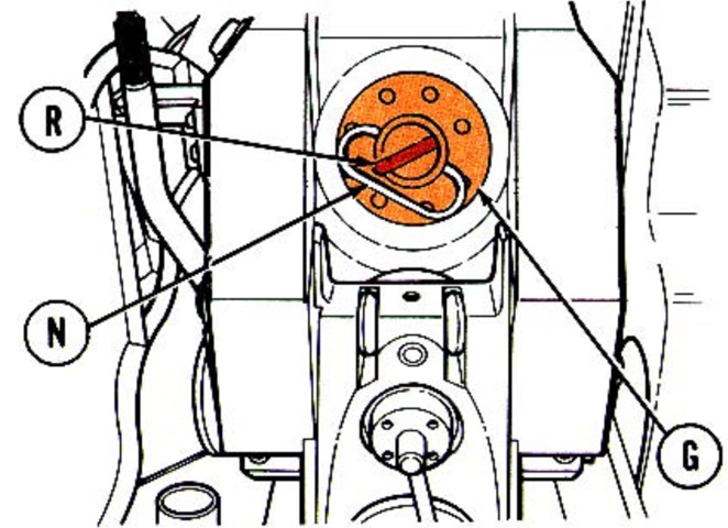
A round (G) is drawn here chambered, showing the latch (R) that secured the handle (N). (Picture from TM 9-2350-222-10-2 C9.)
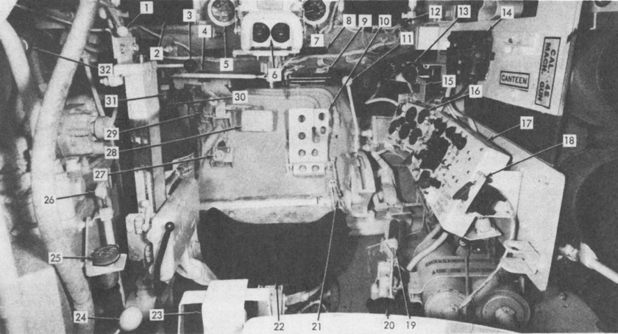
The driver's position is illustrated here. 1. Driver's hatch cover control handle. 2. Periscope, M27 (3). 3. Bulldozer moldboard directional control valve lever. 4. Brake pressure gage. 5. Tachometer. 6. Periscope, M24. 7. Speedometer. 8. Steering control. 9. Heat diffuser sliding door. 10. Accelerator pedal. 11. Transmission shift lever. 12. Dome light (behind periscope). 13. Auxiliary power (slaving) receptacles. 14. Interphone and control box. 15. Hydraulic pump switch and indicator lamp. 16. Gage indicator panel. 17. Master control panel. 18. Generator switch. 19. Purge pump handle and manifold heater switch. 20. Headlight assembly stowage bracket (2). 21. Accelerator locking lever. 22. Seat. 23. Gas particulate filter heater. 24. Drain valve controls (2). 25. Gas particulate filter heater hose. 26. Fuel shut-off valve handle. 27. Dimmer switch. 28. Brake pedal. 29. Turret seal hand pump. 30. Turret seal pressure gage (hidden). 31. Fixed fire extinguishers. 32. Hydraulic selector control valve lever. (Picture from TM 9-2350-222-10 C2.)
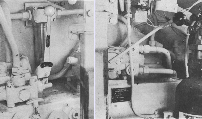
The hydraulic selector control valve on the left had settings for hull, turret, and neutral in order to route hydraulic pressure to the bulldozer system, the turret winch-boom system, or the reservoir, respectively. The bulldozer moldboard directional control valve lever on the right was sprung so that it would remain in the hold position when not in use, which would prevent the moldboard from moving from its current position. Pulling up on the lever would raise the moldboard, and pushing down on the lever lowered the moldboard. Placing the lever in its lowest setting would put the moldboard in the float position, where it would ride along the ground surface. (Picture from TM 9-2350-222-10 C2.)
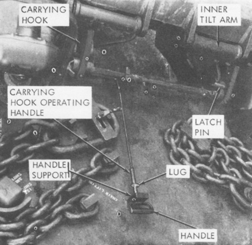
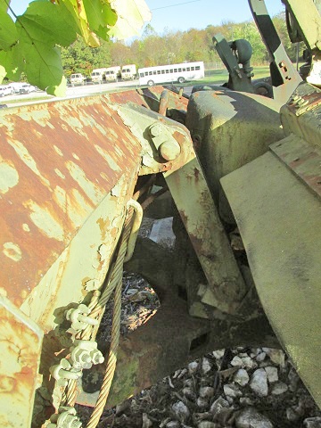
The moldboard was held in position for travel by carrying hooks that engaged pins near the inner tilt arms. (Picture from TM 9-2350-222-10 C2.)
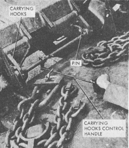
To release the moldboard, it was raised enough to clear the carrying hooks, then the carrying hooks control handle was lifted from its lock position and pushed forward. (Picture from TM 9-2350-222-10 C2.)
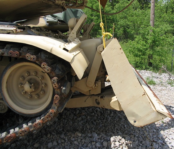
Details of the hydraulically-operated dozer blade are shown here. Note that the headlight groups have been extended to shine over the retracted blade. The tank mounting bulldozer M9 was essentially the M48A2's M8A1 bulldozer modified to fit the M60. The moldboard could be positioned from 10" (25cm) below ground level to 30" (76cm) above ground; carry position was 29" (74cm) above ground level and rate of lift was 2.5"/sec (6.4cm/sec) at 1100 engine rpm.
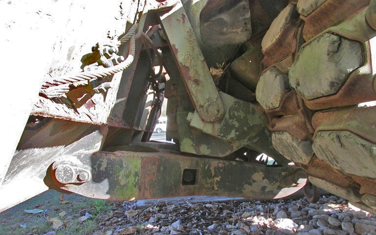
Lower-hull connections for the dozer moldboard are shown in this picture. The lift cable can be seen attached to the near side of the rear of the moldboard. Hydraulic cylinders pushed down on the beam at the bottom to lower the moldboard into the ground.
The moldboard is on the left of this image, and the extended headlight clusters and hydraulic cylinder housings can be seen on the hull to the right. The tilt arm connects to the top rear of the moldboard and would swing forward as the moldboard is lowered.
Fittings on the hull front are detailed here, including the extended headlights, dozer hydraulic cylinders, and lifting chain stays. The carrying hooks control handle can be seen on the far side.
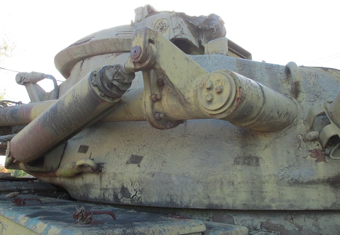
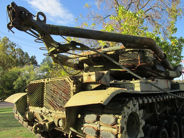
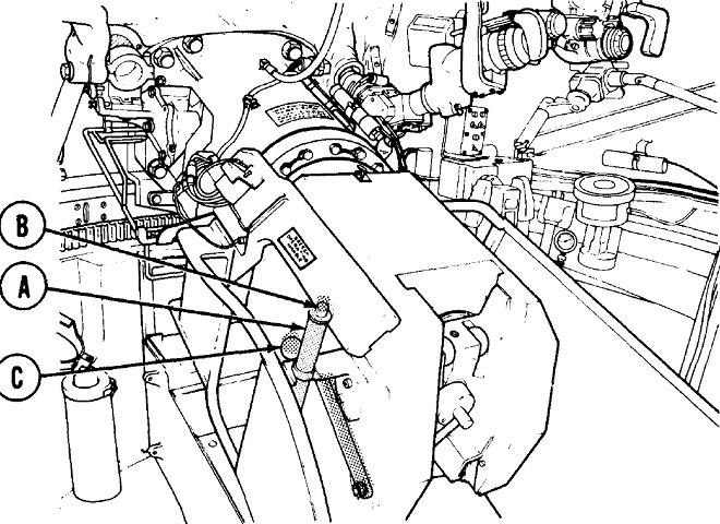
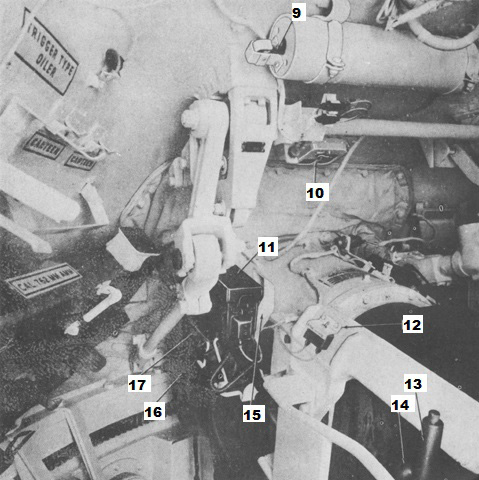
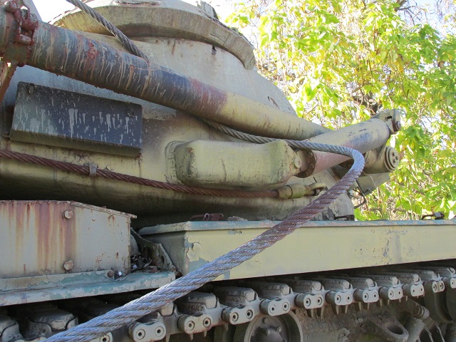
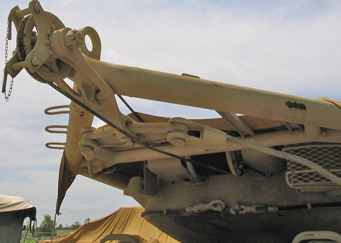
Details of the attachment of the boom to the turret and the linear actuating cylinder are shown in this picture.
The maximum height the boom cable hook could reach was 16.5' (503cm) above the ground.
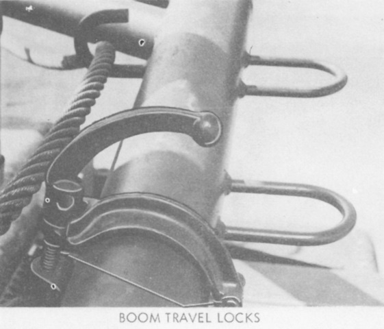
Travel locks similar to those used with gun tubes secured the boom when not in use. (Picture from TM 9-2350-222-10 C2.)
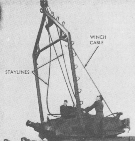
When erecting the boom, the staylines were guided into position by personnel. (Picture from TM 9-2350-222-10 C2.)
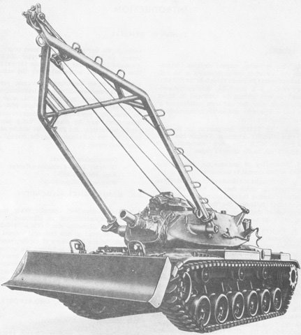
The boom is shown in position here. (Picture from TM 9-2350-222-10 C2.)
The staylines and winch cable can be seen from behind. (Picture from TM 9-2350-222-10 C2.)
The staylines supported the boom and load weight, and were connected to an equalizer bar at the end of the boom. The equalizer bar divided the load equally between the staylines. (Picture from TM 9-2350-222-10 C2.)
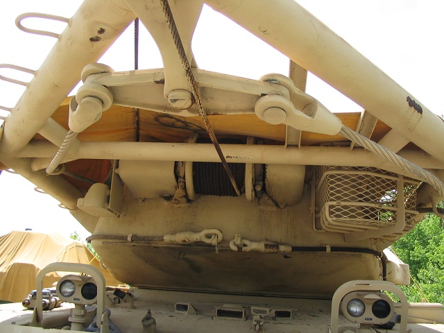
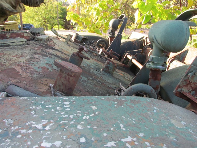
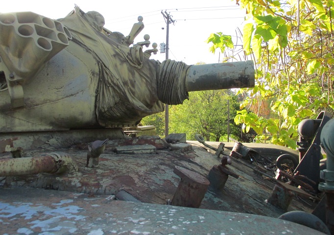
The stayline stabilizer bar and boom bracing are highlighted here, along with the location of the winch, small turret bustle stowage basket, and tow cable stowage. Steps line the left arm of the boom. The turret is reversed on this vehicle, and it is also covered by a tarp.
The winch pulley at the end of the boom is detailed here.
Mounting points for an infrared searchlight can be seen above the gun M135, and a smoke grenade launcher is positioned on the turret front. The maximum, normal, and minimum lengths of recoil for the concentric hydrospring recoil mechanism were 13.5" (34.3cm), 12" (30cm), and 8.75" (22.2cm), respectively. The ordnance weighed 1,465lb (664.5kg), and its muzzle velocity was 850ft/s (260m/s).
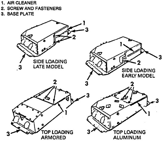
The different types of engine air cleaners are illustrated here. Top loading air cleaners were introduced to the M60A1 in 1971, and they were armored beginning in January 1977. (Picture from TM 9-2350-222-10-1 C6.)
