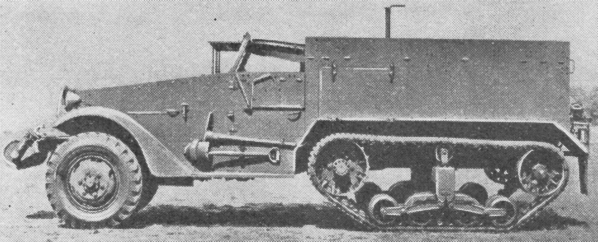
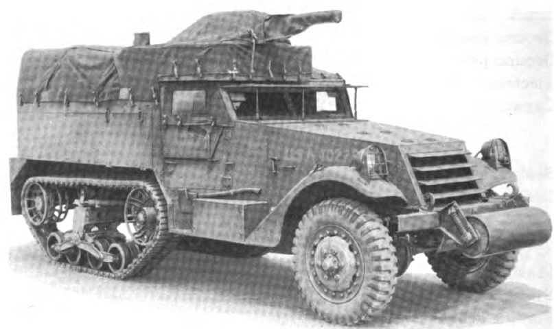
Half-track Car M2.
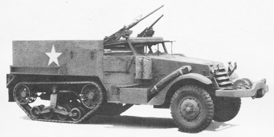
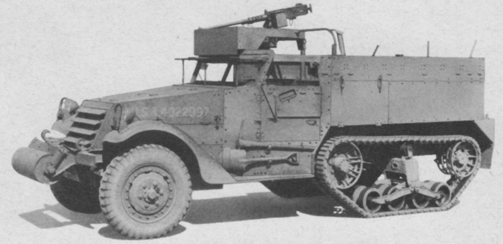
The shorter body of the half-track car M2 compared to its personnel carrier M3 cousin can be seen in this view. This early vehicle lacks mine racks and has an unsprung idler wheel. (Picture from FM 30-40 C1 Military Intelligence Identification of United States Armored Vehicles.)
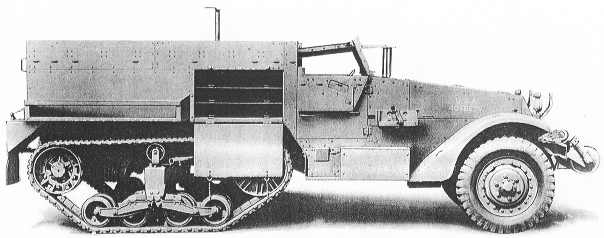
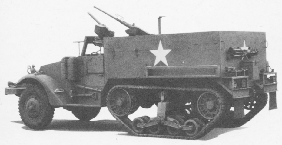
The side ammunition compartment is open, showing the shelving inside. The mine rack on the M2 was necessarily shorter than that found on the personnel carrier half-tracks due to these compartments. The machine gun skate rail can be seen between the windshield and the passenger compartment, and the groups of four screws near the top of the rear compartment armor attach the skate rail to the vehicle. This vehicle has the double coil idler spring, demountable headlights, and is fitted with a roller. The armored windshield flap is raised, and an antenna mount rises from the rear compartment. (Picture from Standard Nomenclature List G-102.)
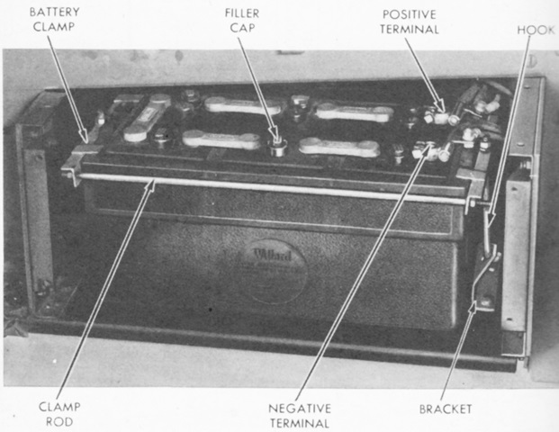
The 12-volt, 6-cell, 25-plate, lead-acid, safety-fill vent type battery was housed in an enclosure on the side of the frame below the right side cab door. (Picture from TM 9-710 Basic Half-Track Vehicles (White, Autocar, and Diamond T).)
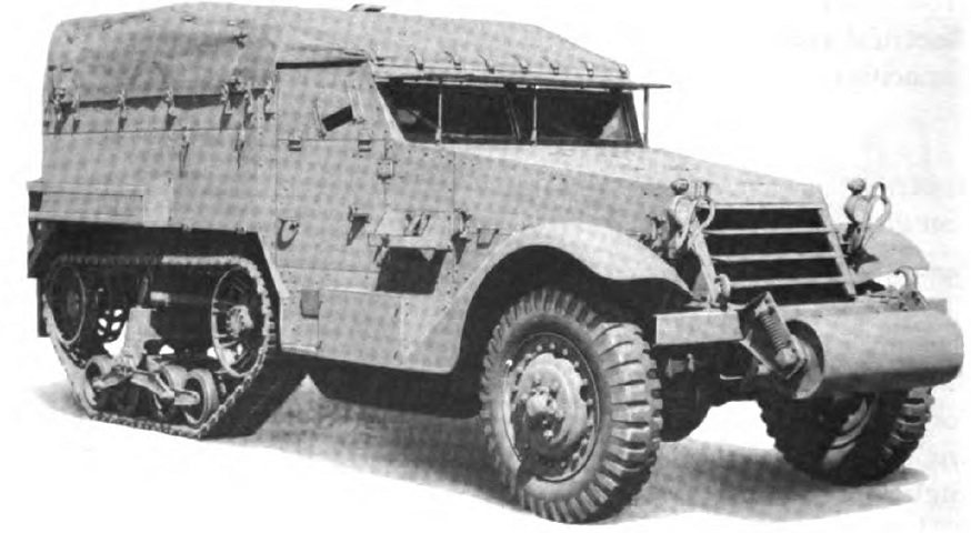
The canvas cover over the passenger compartment is installed on this vehicle. (Picture from TM 9-2800 Standard Military Motor Vehicles.)
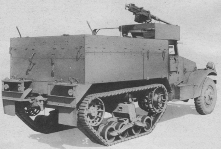
This machine is fully stowed, including both machine guns. A winch is fitted instead of a roller. (Picture from TM 9-710 Basic Half-Track Vehicles (White, Autocar, and Diamond T).)
Rear stowage, including a machine gun tripod, can be seen from this angle. The lack of a battery box on the left-side running board makes it more user-friendly. (Picture from TM 9-710 Basic Half-Track Vehicles (White, Autocar, and Diamond T).)
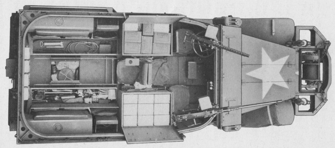
All stowage bins are opened in this half-track. The seat cushions could be swung upwards, the top shelves of the ammunition stowage compartments are visible, and floor stowage was available as well. This vehicle has the smaller, later headlights and is equipped with a winch. Mine racks are also present on the sides of the passenger compartment. The right-angled corners of the fighting compartment are apparent, and the skate rails for the two machine guns can be seen inside the passenger compartment. The vehicle's fuel tanks can be seen in the rear corners of the passenger compartment. (Picture from TM 9-710 Basic Half-Track Vehicles (White, Autocar, and Diamond T).)
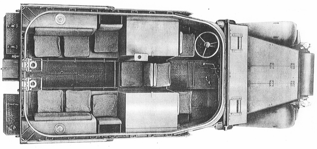
The stowage compartments are closed in this image, showing the seating arrangement of 3 in the cab and 7 in the rear compartment. Two machine gun carriages are mounted on the skate rail at the rear of the vehicle. (Picture from Standard Nomenclature List G-102.)
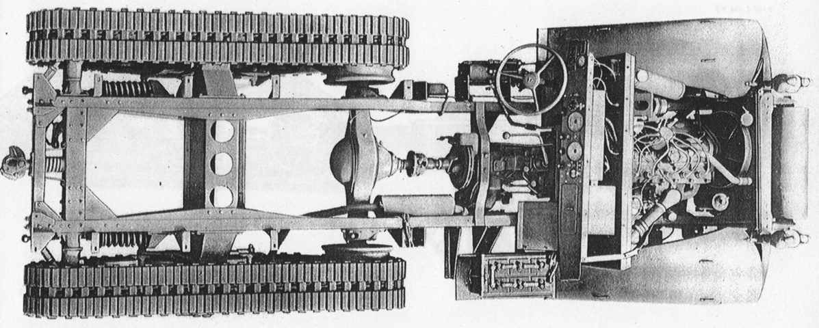
The chassis is seen from above without the body. (Picture from Standard Nomenclature List G-102.)
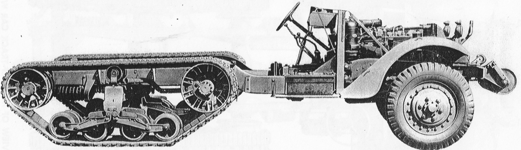
The rolling chassis is shown from the right. (Picture from Standard Nomenclature List G-102.)
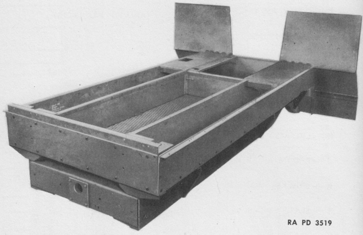
The rear floor frame assembly of the half-track car body has been bolted to the vehicle frame. (Picture from TM 9-1710C Ordnance Maintenance--Chassis and Body for Half-track Vehicles.)
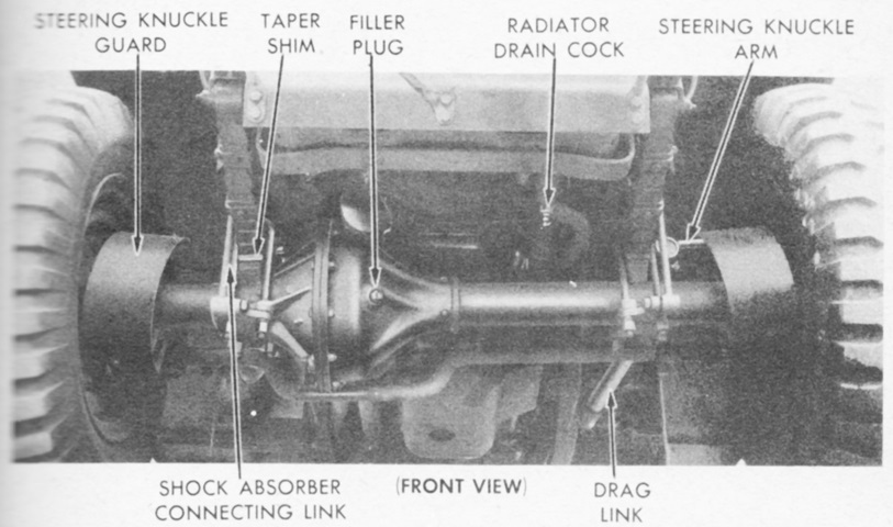
The Timken F-35-HX-1 front axle was a single-reduction full-floating type with a straddle mounted pinion gear and a conventional differential. The front wheels were driven via CV joints enclosed within the steering knuckles. The CV joint boots were protected by brush guard pins. The unlabeled tie rod can be seen behind the axle snaking around the differential. (Picture from TM 9-710 Basic Half-Track Vehicles (White, Autocar, and Diamond T).)
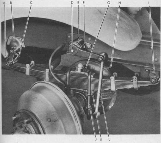
The front suspension consisted of semi-elliptical leaf springs, and each wheel also was connected to a double-acting Houdaille shock absorber. The legend is as follows: A. Shackle. B. Rear anchor bracket. C. Shackle pins. D. Adjusting indicator. E. Shock absorber. F. Filler plug. G. Spring bumper block. H. Connecting link. I. Front shackle bracket. J. U-bolts. K. Front axle bracket. L. Tapered shim. (Picture from TM 9-710 Basic Half-Track Vehicles (White, Autocar, and Diamond T).)
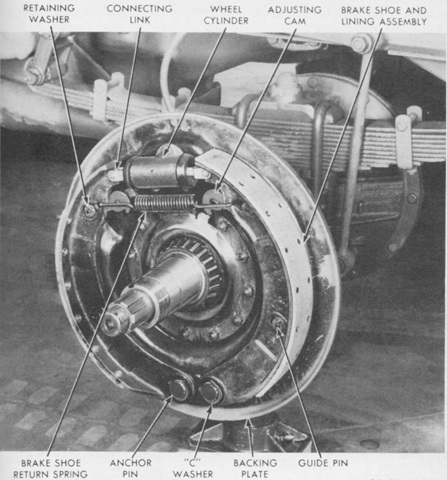
One of the front brake shoes is shown here installed. The brakes were Wagner Electric model LO-FC-7762 hydraulic two-shoe internal expanding types. (Picture from TM 9-710 Basic Half-Track Vehicles (White, Autocar, and Diamond T).)
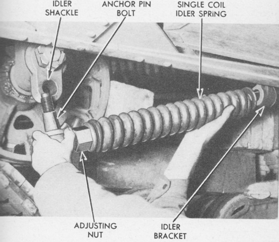
Details of the mounting of the single coil idler wheel spring can be seen here. (Picture from TM 9-710 Basic Half-Track Vehicles (White, Autocar, and Diamond T).)
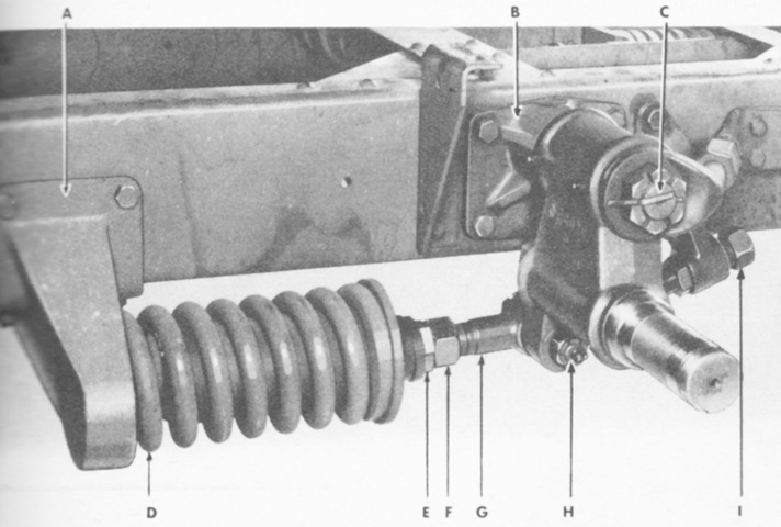
The shorter and stouter double coil idler spring assembly can be contrasted with the image above. The legend is: A. Idler spring bracket. B. Idler post bracket. C. Idler post. D. Idler spring. E. Adjusting nut. F. Jam nut. G. Idler adjusting screw. H. Anchor pin bolt. I. Idler stop screw. (Picture from TM 9-710 Basic Half-Track Vehicles (White, Autocar, and Diamond T).)
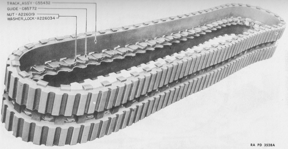
The T68E1 endless track assembly was made of rubber molded around steel cables that extended throughout its length to prevent stretching. Metal guides were bolted along the center of the track and also engaged the drive sprocket teeth. When needed, grouser wing bolts could be hooked over the tabs along the sides of the tracks. (Picture from TM 9-1710C Ordnance Maintenance--Chassis and Body for Half-track Vehicles.)
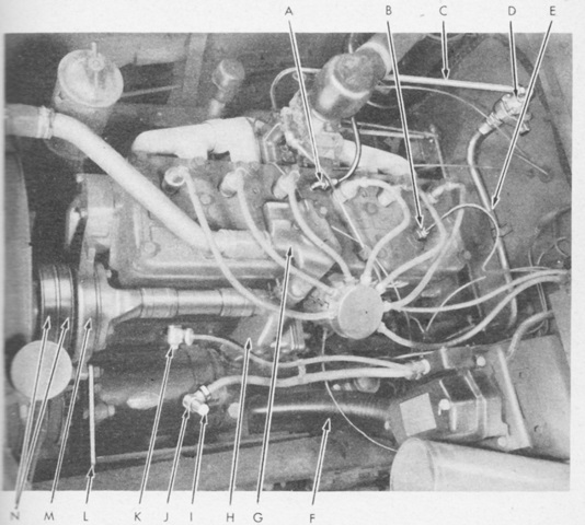
The White 160AC was an L-head type engine with a 386in³ (6330cc) displacement. Cylinder bore was 4" (10cm), stroke was 5.125" (13.02cm), and compression ratio was 6.44:1. A. Crankcase breather tube coupling. B. Water temperature gage bulb. C. Intake to check valve vacuum line. D. Check valve. E. Check valve to Hydrovac vacuum line. F. Cab ventilator air funnel. G. Thermostat housing. H. Oil temperature regulator. I. Condenser. J. Armature terminal. K. Field terminal shield. L. Adjusting strap. M. Water pump. N. Fan belts. (Picture from TM 9-710 Basic Half-Track Vehicles (White, Autocar, and Diamond T).)
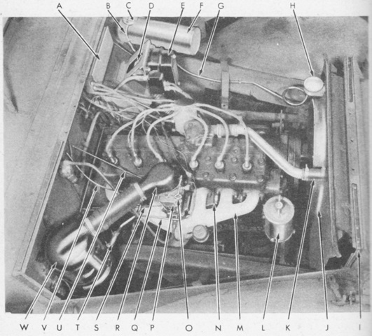
The opposite side of the engine is illustrated here. A. Ignition coil box. B. Overflow. C. Pressure cap. D. Hydrovac air cleaner. E. Voltage regulator. F. Surge tank. G. Surge tank line. H. Radiator filler cap. I. Anti-squeak. J. Shroud. K. Radiator inlet pipe. L. Oil filter. M. Exhaust manifold. N. Intake manifold. O. Thumb screw. P. Carburetor. Q. Throttle rod. R. Air cleaner horn. S. Throttle rod return spring. T. Crankcase breather tube hose. U. Hand throttle cable. V. Choke cable. W. Air cleaner. (Picture from TM 9-710 Basic Half-Track Vehicles (White, Autocar, and Diamond T).)
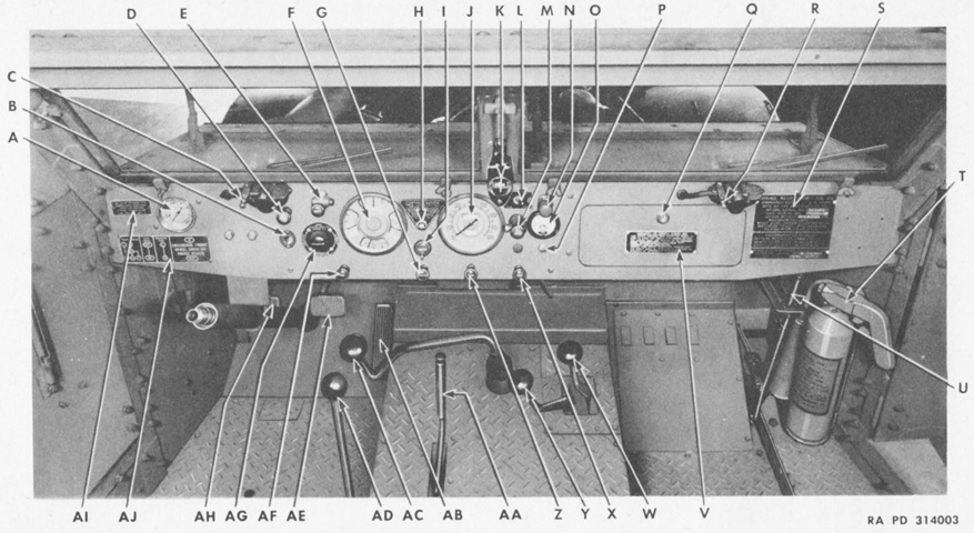
The instruments and controls are labeled in this picture. Inside the dash under the instrument panel, a Bishop and Babcock model BI-X24109 hot water-type heater with an electric circulation fan was installed. It used a valve to route engine coolant through the heater core, and a rheostat switch on the instrument panel controlled the fan speed. A. Tachometer. B. Trouble light receptacle. C. Windshield wiper control--left unit. D. Panel light control rheostat. E. Main light switch. F. Instrument cluster [clockwise from top: ammeter, oil pressure gage, temperature gage, fuel gage]. G. Throttle control. H. Starter push button. I. Ignition switch. J. Speedometer. K. Compass. L. Fuel tank selector switch. M. Blackout driving light switch. N. Dash light. O. Voltmeter. P. Voltmeter push button. Q. Map compartment door. R. Windshield wiper control--right unit. S. Vehicle registration plate. T. Fire extinguisher. U. Radiator shutter control lever. V. Winch caution plate. W. Front axle drive shift lever. X. Ventilator control--right hand. Y. Transfer case shift lever. Z. Choke control. AA. Parking brake lever. AB. Accelerator pedal. AC. Transmission gear shift lever. AD. P.T.O. shift lever. AE. Brake pedal. AF. Ventilator control--left hand. AG. Electric brake load control. AH. Clutch pedal. AJ. Gear shift instrument plate. AI. Engine caution plate. (Picture from TM 9-710 Basic Half-Track Vehicles (White, Autocar, and Diamond T).)
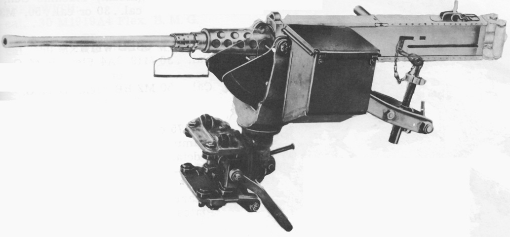
The skate mount M30 could accept either a .30cal or .50cal machine gun, and is shown here with a .50cal mounted. Although the rail provided 360° coverage, traverse in the mount itself was limited to 160° (80° left and right). The later skate mount M35 differed by having a T-shaped support for the rear of the gun instead of the M30's support that included a mechanism for fine traverse and elevation adjustments. The M35's traverse and elevation limits were the same as the M30's. (Picture from Weapon Mounts for Secondary Armament.)
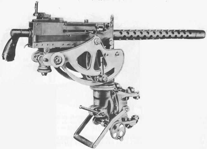
The skate mount M29 was restricted to the .30cal machine gun. Its traverse was identical to that of the skate mount M30. (Picture from Weapon Mounts for Secondary Armament.)
The machine gun skate rail has been replaced by the .50cal ring mount on the front, and three pintle mounts in the passenger compartment could mount the .30cal MG. The armor protection for the ring mount gunner did not continue all the way around, as can be seen in this image. (Picture from TM 9-710 Basic Half-Track Vehicles (White, Autocar, and Diamond T).)
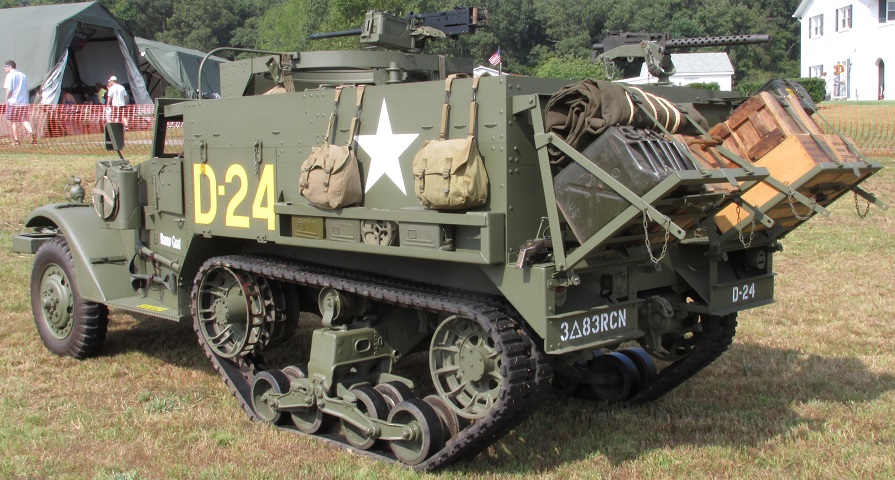
"Nanny Goat" has been fitted with folding stowage racks at the rear, and the shorter half-track car body necessitated that the racks be angled outward in order to attach to the rear bumper. The rear machine gun pintle is occupied; other machine gun mounts were available on each side of the rear compartment. The solid triangular side pieces on the rear bumpers mark this vehicle as being manufactured by Autocar. Vehicles manufactured by White had open triangular pieces.
With the advent of the new machine gun position, the canvas cover was necessarily modified. (Picture from TM 9-2800 Standard Military Motor Vehicles.)
A towing pintle hook can be seen on the vehicle's rear, and tripods for the .50cal and .30cal machine guns were usually stowed on the rear of the half-track along with bows for the passenger compartment cover. This half-track is fitted with the early, larger headlights. (Picture from TM 9-710 Basic Half-Track Vehicles (White, Autocar, and Diamond T).)
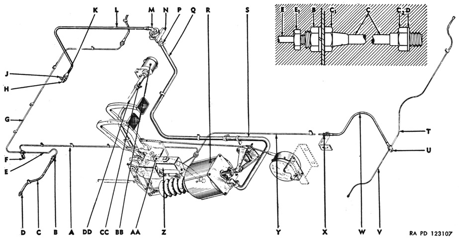
The original brake system used engine vacuum to help boost the pressure applied to the brake master cylinder piston. Hydraulic lines (to front wheel brakes): A. Pipe assy--master cylinder to tee. B. Nut, w/lock washer--securing hose to pipe assy. C. Hose--pipe assy to wheel brake cylinder. C1. Rigid nut--on pipe assy at frame. C2. Rigid nut--on pipe assy at wheel cylinder. D. Gasket--hose to cylinder. E. Pipe assy--tee to left wheel brake cylinder. E1. Nut--coupling pipe assy to hose. F. Tee--w/screw, nut, and lock washer. G. Pipe assy--tee to right wheel brake cylinder.
Vacuum lines (manifold to booster): H. Nipple--to manifold. J. Connector--to vacuum pump. K. Flared tube nut. L. Pipe assy--manifold to check valve. M. Elbow--top of check valve. N. Check valve assy mounting bracket. P. Tube nut--bottom of check valve. Q. Pipe assy--check valve to power cylinder. R. Power cylinder assy. S. Hose--check valve to power cylinder.
Hydraulic lines (to rear wheel brakes): T. Pipe assy--tee to right wheel brake cylinder. U. Tee, w/screw and washers--hose to pipe assy. V. Pipe assy--tee to left wheel brake cylinder. W. Hose--adapter to tee. X. Adapter, w/nut and lock washer--pipe assy to hose. Y. Pipe assy--master cylinder to adapter. Z. Master cylinder assy.
Vacuum lines (air cleaner to booster): AA. Hose--pipe assy to power cylinder. BB. Air cleaner assy. CC. Hose, w/clamp--air cleaner to pipe assy. DD. Pipe assy--air cleaner to power cylinder. (Picture from TM 9-710/TO 19-75A-77.)
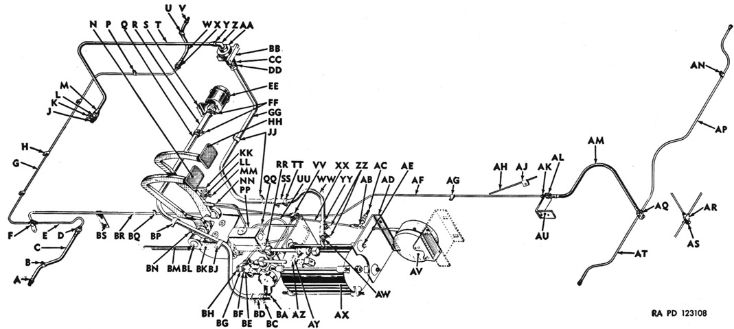
The hydrovac booster instead acted directly on the hydraulic fluid leading to the brake cylinders instead of on the master cylinder piston. A. Nut. B. Tube clip. C. Hydraulic hose. D. Nut. E. Hydraulic line to left front brake. F. Hydraulic brake line tee. G. Hydraulic line to right front brake. H. Tube clip. J. Fitting. K. Windshield wiper lines connector: plug used instead for 75-M3. L. Plug. M. Flare tube nut. N. Clutch pedal. P. Tube clip. Q. Atmospheric tube assy from air cleaner to hydrovac. R. Hose. S. Air cleaner mounting bracket. T. Vacuum line from manifold to check valve. U. Tube clip. V. Nut. W. Hydraulic hose. X. Nut. Y. Flared tube nut. Z. Elbow. AA. Check valve assy. BB. Rubber mounting bracket. CC. Fitting. DD. Tube nut. EE. Air cleaner assy. FF. Hose clamps. GG. Vacuum line assy from check valve to hydrovac. HH. Brake pedal. JJ. Tube clips. KK. Brake pedal stop bracket. LL. Nut. MM. Cap screw stop. NN. Clutch and brake pedal support bracket. PP. Master cylinder assy. QQ. Hydraulic line assy from master cylinder to hydraulic cylinder. RR. Stop light hydraulic switch. SS. Hose. TT. Hose clamp. UU. Hydraulic line assy from hydraulic cylinder to tubing tee at frame rail. VV. Hydraulic brake lines tee. WW. Vacuum tube. XX. Electric brake controller rod. YY. Hose. ZZ. Hose clamps. AB. Electric brake controller rod relay lever. AC. Electric brake controller rod shaft and spacer. AD. Hydrovac rear mounting bracket. AE. Hydrovac stud nut and washer. AF. Hydraulic line assy to rear brake connection.‡ AG. Tube clip. AH. Hydraulic line assy to rear brake connection.* AJ. Tube clip. AK. Union.‡ AL. Nut.‡ AM. Hose.‡ AN. Clip. AP Hydraulic line to right rear brake. AQ. Hydraulic brake line tee.‡ AR. Hydraulic brake line tee.* AS. Cap screw and washer.* AT. Hydraulic line to left rear brake. AU. Frame bracket.‡ AV. Electric brake controller assy. AW. Hose nipple. AX. Hydrovac. AY. Washer. AZ. Connector. BA. Hose elbow. BC. Hose clamp. BD. Hose. BE. Valve relay body. BF. Nut. BG. Fitting. BH. Nut. BJ. Tube clip. BK. Master cylinder rod end yoke. BL. Clutch and brake pedal shaft. BM. Brake pedal return spring. BN. Master cylinder operating lever. BP. Tube clip. BQ. Tube clip. BR. Hydraulic line assy to front brake line tee. BS. Tube clip. (Note: omit ‡ when * are used.) (Picture from TM 9-710/TO 19-75A-77.)
