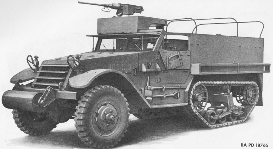
Half-track Personnel Carrier M5.
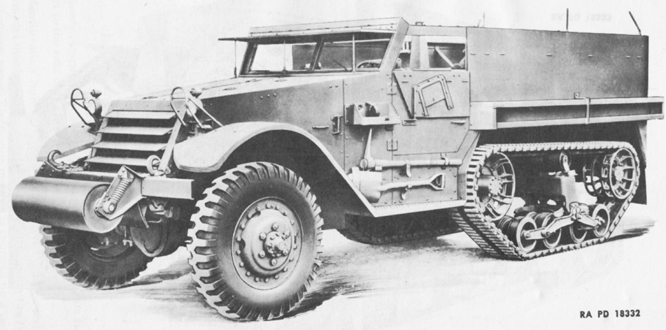
The half-track M5 was very similar to the M3, but the mechanicals and armor construction were different, with International Harvester vehicles lacking the characteristic screw assembly of the face-hardened half-tracks. One can make out that the mount for the shutter in the folding armored window shield is attached on the inside of the window when it is raised, and outside when it is folded down. Half-tracks manufactured by Diamond T, Autocar, and White had the shutter attached on the opposite side. (Picture from TM 9-707 Basic Half-Track Vehicles (IHC).)
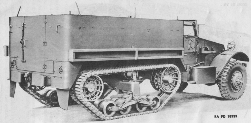
In contrast to the face-hardened armor on half-tracks manufactured by White, Autocar, and Diamond T, the rolled homogeneous armor used in IHC half-tracks could be formed, allowing curved corners at the rear of the passenger compartment. (Picture from TM 9-707 Basic Half-Track Vehicles (IHC).)
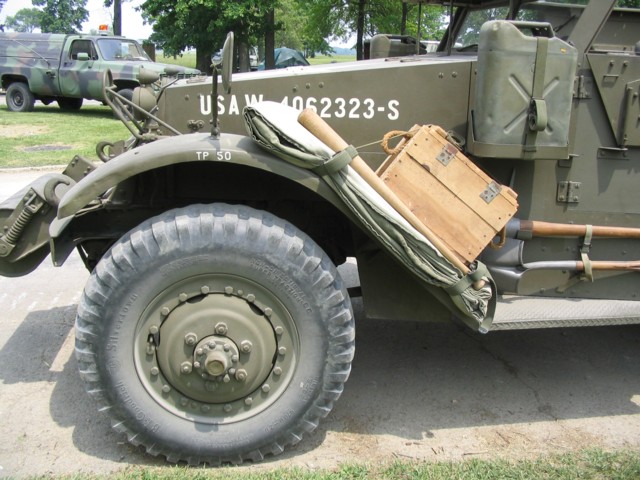
Compared to those on half-tracks produced by White, Autocar, and Diamond T, the fenders on this M5 have a thin side view. Like all M5s, this vehicle is fitted with the small, demountable headlights. The headlight brush guard design also differed on IHC half-tracks.
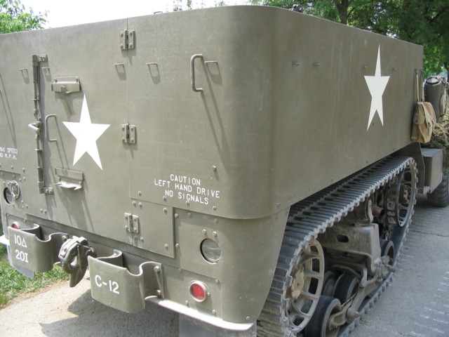
The rounded rear corners and smooth passenger compartment exterior are hallmarks of IHC half-tracks. Note also the protruding rear bumperettes and the way that the rear armor steps inward from the upper armor down to the bumper frame.
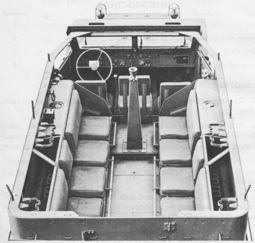
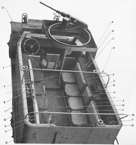
The internal layout of the M5 was essentially the same as that of the half-track M3. The machine gun mount can be seen near the front, behind the three front seats; the fuel tanks are near the cab; and seating and stowage are towards the rear. (Picture from TM 9-707 Basic Half-Track Vehicles (IHC).)
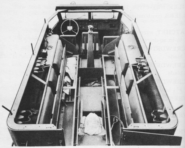
The stowage compartments under the troop seats and under the passenger compartment floor are open in this image. (Picture from TM 9-707 Basic Half-Track Vehicles (IHC).)
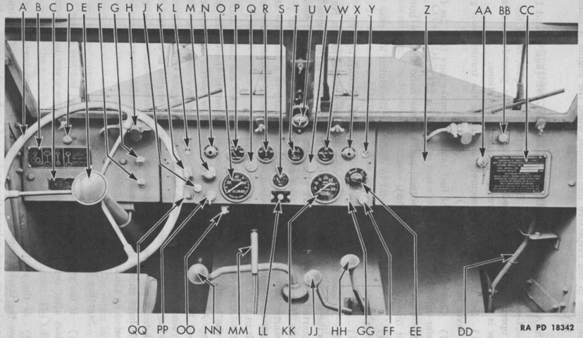
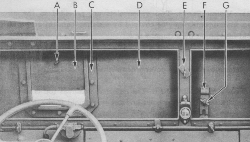
The controls and instruments are illustrated here. A. Steering wheel. B. Gear shift instruction plate. C. Winch operation caution plate. D. Compartment vent covers. E. Horn button. F. Throttle control. G. Choke control. H. Windshield wiper assembly. J. Panel light switch. K. Blackout driving lamp switch. L. Inspection lamp socket. M. Blackout and service light switch. N. Oil pressure warning light. O. Speedometer. P. Oil pressure gage. Q. Panel light cover. R. Ammeter. S. Fuel gage. T. Voltmeter. U. Compass. V. Panel light cover. W. Coolant temperature gage. X. Coolant temperature gage warning light. Y. Inspection lamp socket. Z. Map compartment door. AA. Map compartment door lock. BB. Air cleaner control. CC. Vehicle registration plate. DD. Radiator shutter control lever. EE. Rheostat load control for trailer brakes. FF. Map reading lamp. GG. Map reading lamp switch. HH. Front axle shift lever. JJ. Transfer case shift lever. KK. Tachometer. LL. Fuel tank selector switch. MM. Hand brake lever. NN. Transmission shift lever. OO. Speedometer re-set shaft. PP. Ignition switch. QQ. Starter button. (Picture from TM 9-707 Basic Half-Track Vehicles (IHC).)
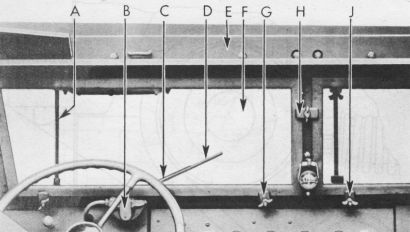
The armored plate for the windshield is raised in this picture. A. Windshield armor left support rod assembly. B. Windshield wiper assembly. C. Windshield wiper arm. D. Windshield wiper blade. E. Windshield header. F. Left windshield, with glass, assembly. G. Windshield half clamp. H. Windshield full clamp. J. Windshield wing nut. (Picture from TM 9-707 Basic Half-Track Vehicles (IHC).)
The armored plate for the windshield has been lowered. A. Windshield armor port hole cover thumb screw. B. Windshield armor port hole cover. C. Port hole cover retainer. D. Windshield armor plate assembly. E. Center retainer. F. Armor plate retaining clamp. G. Wing nut. (Picture from TM 9-707 Basic Half-Track Vehicles (IHC).)
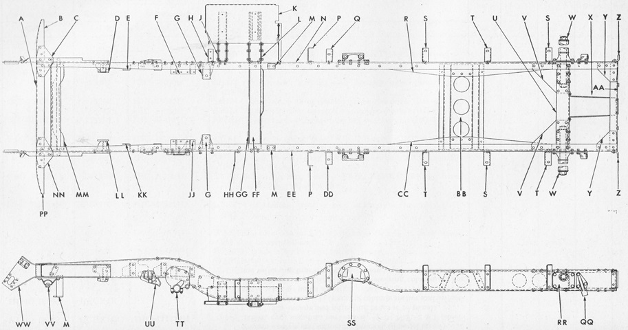
The chassis frame is sketched in elevation and plan. (Picture from ORD 7-8-9 SNL G-147.)
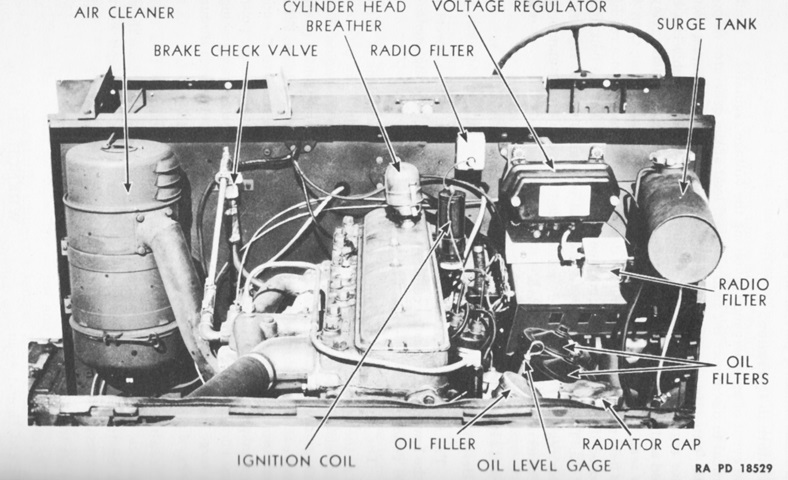
The engine is shown here from the front. (Picture from TM 9-707 Basic Half-Track Vehicles (IHC).)
The right side of the transmission and transfer case is diagrammed here. A. Front axle drive shift lever. B. Transfer case gear shift lever. C. Shift lever spacer. D. Hand brake lever. E. Transmission case gear shift lever. F. Shift lever housing to case stud (4) with nut (4) and lockwasher (4). G. Breather cap. H. Clutch release bearing lubricator tube. J. Clutch release bearing. K. Clutch housing cover plate. L. Clutch housing. M. Clutch housing to case screw (4) with lockwasher (4). N. Drain plug. O. Shift link rod-end pin (4) with cotter pin (4). P. Shift lever retainer nut with washer and cotter pin. Q. Shift link (2). (Picture from TM 9-707 Basic Half-Track Vehicles (IHC).)
The left side of the transmission and transfer case is diagrammed here. A. Hand brake lever. B. Transfer case gear shift lever. C. Front axle drive shift lever. D. Clutch release lever. E. Lubricant level plug. F. Clutch housing. G. Shift lever housing. H. Transmission case gear shift lever. (Picture from TM 9-707 Basic Half-Track Vehicles (IHC).)
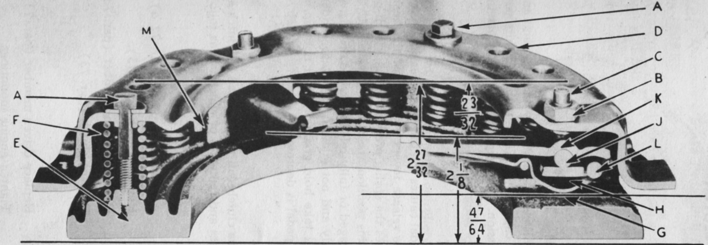
A sectionalized view of the single plate, dry disk clutch is shown in this image. The clutch assembly weighed 51lb (23kg). A. Capscrew and flat washer. B. Adjusting screw lock nut. C. Release lever adjusting screw. D. Clutch cover plate. E. Clutch pressure plate. F. Clutch pressure spring. G. Lever spring. H. Block. J. Hardened roller. K. Release lever. L. Lever retaining pin. M. Drive lug. (Picture from TM 9-707 Basic Half-Track Vehicles (IHC).)
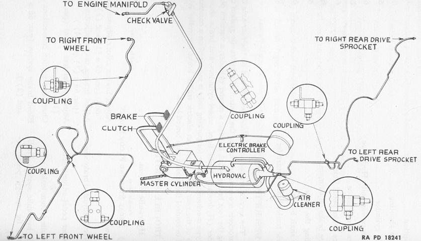
The service brake system is diagrammed here. A manually-operated electric brake controller for trailers was connected to the brake pedal via an adjustable linkage. This allowed the activation of electric trailer brakes simultaneously with those of the half-track. The intensity of application of the electric brake controller was adjusted with a dash-mounted rheostat. The Hydrovac vacuum power unit was made up of a double-piston vacuum-suspended power cylinder, an hydraulic operating valve, and an hydraulic sleeve cylinder. The Hydrovac assisted with the brake application effort and reduced the pedal force used for brake application. (Picture from TM 9-707 Basic Half-Track Vehicles (IHC).)
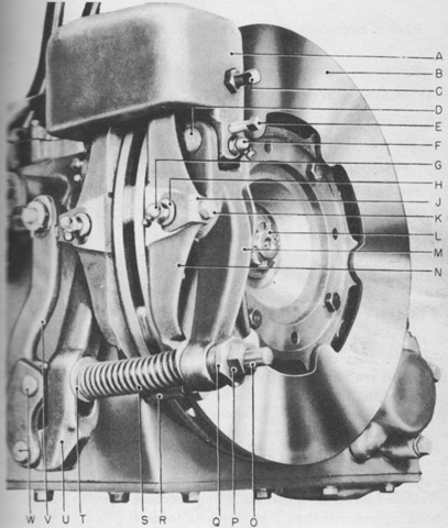
A ventilated disc brake was mounted on the propeller shaft companion flange between the transmission and rear axle, and this acted as the vehicle's parking hand brake. A. Brake anchor bracket. B. Brake disc assembly. C. Brake shoe adjusting set screw(2), w/lock nut(2). D. Lever arm anchor pin(2). E. Lever arm anchor pin lock screw(2). F. Lever arm anchor pin lubricating fitting(2). G. Brake shoe pin lubricating fitting(2). H. Brake shoe pin(2). J. Brake shoe pin retainer. K. Brake shoe pin retainer screw(2), w/lock washer(2). L. Companion flange nut. M. Brake shoe rear lever arm. N. Brake shoe(2). O. Operating lever tie rod. P. Tie rod lock nut. Q. Tie rod spherical nut. R. Brake shoe spring. S. Lever arm release spring. T. Release spring washer. U. Brake shoe front lever arm. V. Operating lever. W. Operating lever clevis pin w/cotter pin(2). (Picture from TM 9-707 Basic Half-Track Vehicles (IHC).)
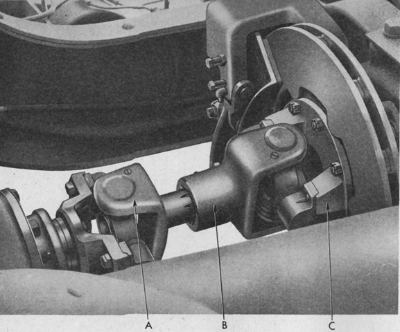
The rear axle propeller shaft is shown here installed into the transmission; the brake is visible to the right. A. Yoke. B. Yoke, w/Plug, ass'y. C. Adapter. (Picture from ORD 7-8-9 SNL G-147.)
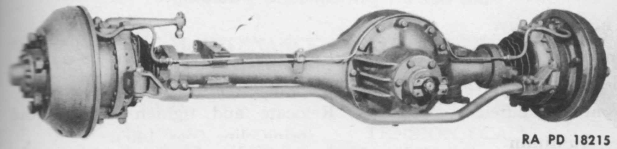
The front axle assembly weighed 820lb (370kg) and was a single-reduction, full floating unit with a straddle-mounted bevel-drive pinion and a conventional type differential. Steering knuckles at the outer ends of the axle housing enclosed constant-velocity universal joints which drove the front wheels. (Picture from TM 9-707 Basic Half-Track Vehicles (IHC).)
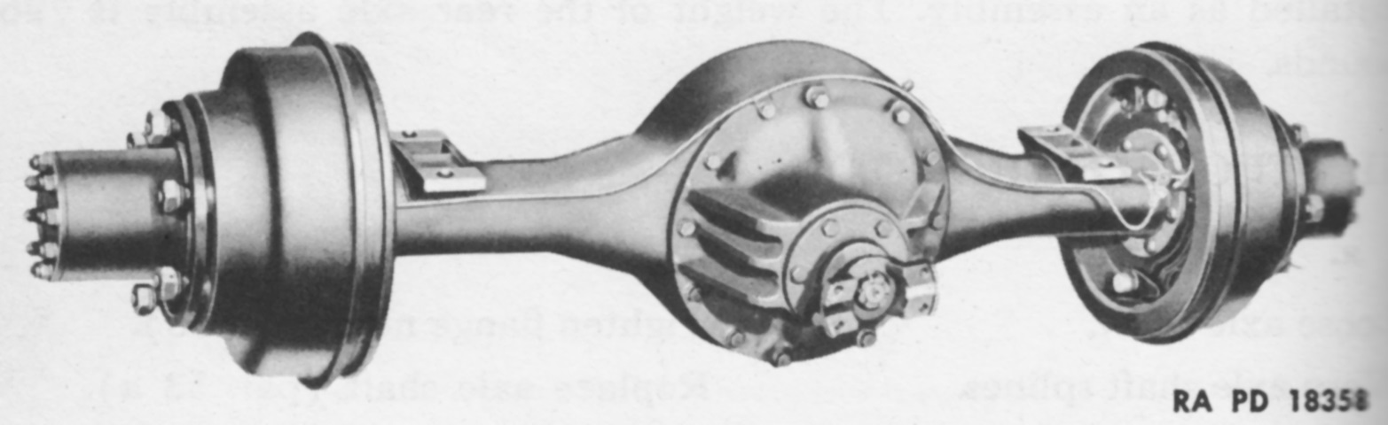
The rear axle assembly weighed 796lb (361kg) and was a single-reduction type with a straddle-mounted bevel-drive pinion and a conventional type differential. The housing was a banjo type, with the differential and differential carrier installed as an assembly. (Picture from TM 9-707 Basic Half-Track Vehicles (IHC).)
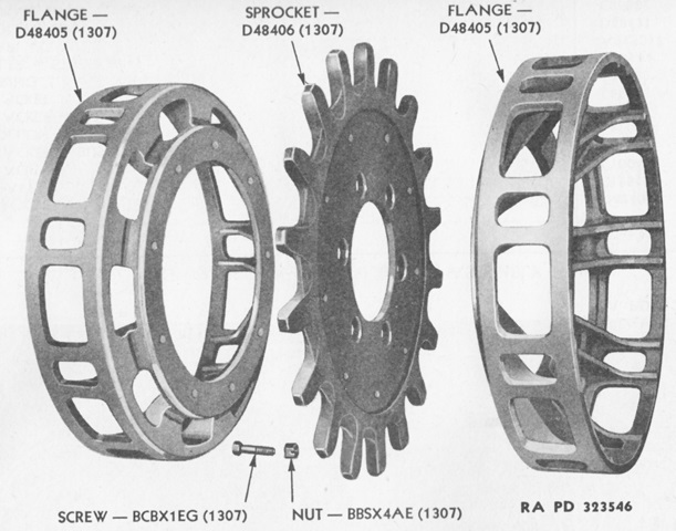
A disassembled drive sprocket is labeled in this image. (Picture from ORD 7-8-9 SNL G-147.)
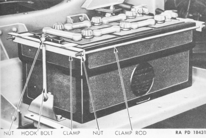
The 6-cell, 25 plate/cell, lead acid type battery was mounted in the normal location under the right cab door. It was rated at 168 ampere hours at a 6-hour rate, and weighed 165lb (74.8kg). (Picture from TM 9-707 Basic Half-Track Vehicles (IHC).)
The ring mount for the .50cal machine gun is obvious above the right-side portion of the cab. (Picture from ORD 7-8-9 SNL G-147.)
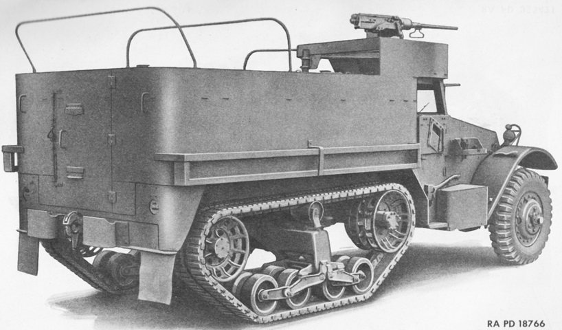
The rear of the ring mount can be seen from this angle. (Picture from ORD 7-8-9 SNL G-147.)
This overhead view shows the installation of the ring mount as well as the machine gun rail itself. Pintle mounts were also present on each side and to the right of the rear door. (Picture from ORD 7-8-9 SNL G-147.)
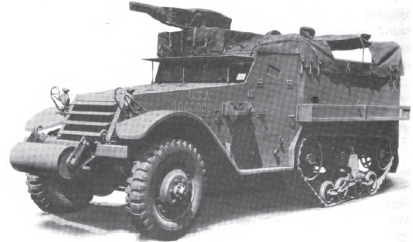
The MG ring mount is under a canvas cover, and the cover over the passenger compartment is illustrating how it could be partially opened. (Picture from TM 9-2800 Standard Military Motor Vehicles.)
