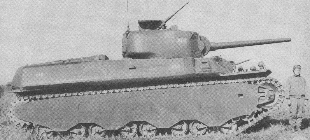
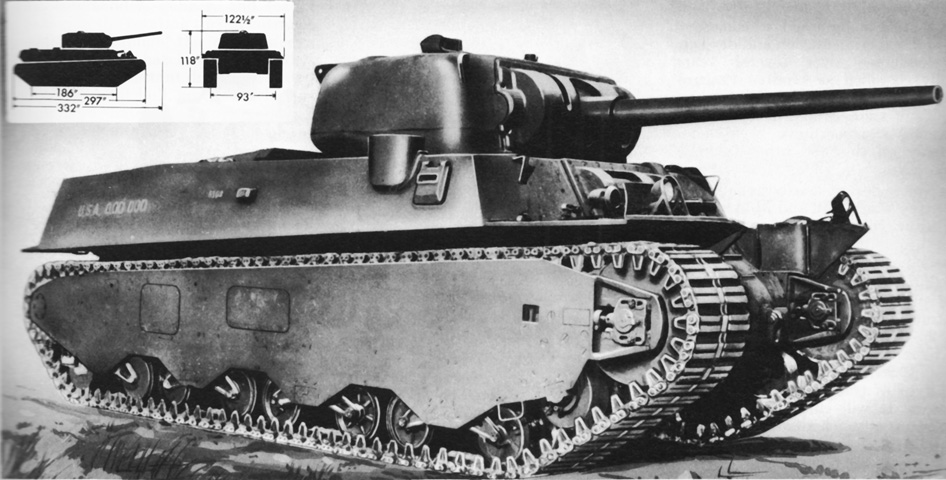
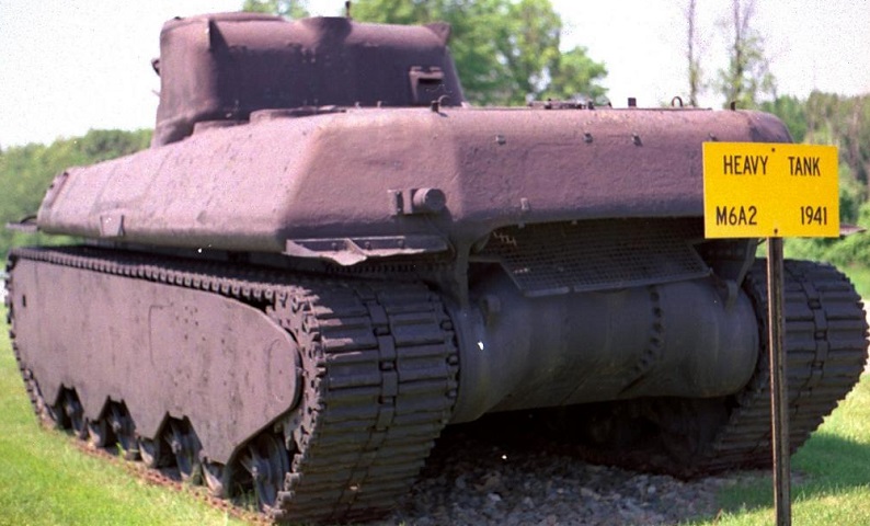
Heavy Tank M6.
The M6 heavy tank was nothing if not imposing, as this view illustrates. The smooth lines of the cast hull are apparent here. Hidden behind the 3" gun is the coaxial 37mm gun, which was similar to the main armament of the M2 medium tank produced three years previously. A .50cal machine gun is partially hidden by the open turret hatch (Armored Force policy vacillated between using a .50cal and .30cal AAMG), and two more .50cal MGs were mounted in the right bow. Just behind the pistol port for the assistant driver is an antenna mount. (Picture from Development of Armored Vehicles, volume 1: Tanks.)
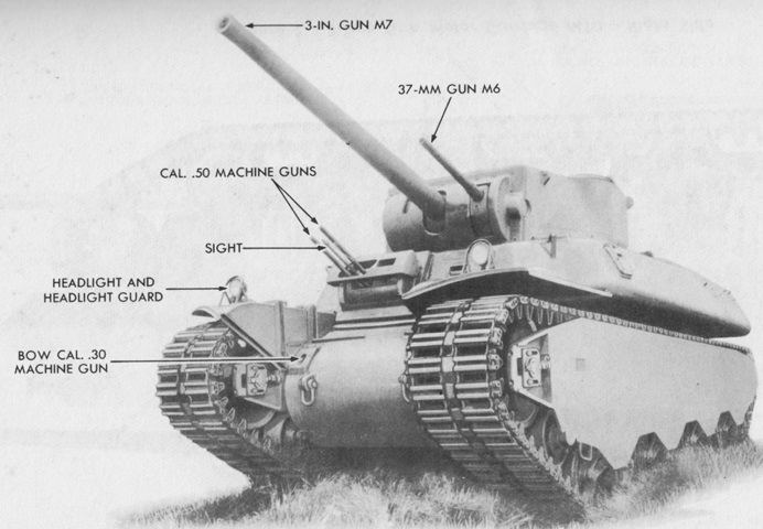
The position of the tank's weapons are illustrated in this picture. No coaxial machine gun was mounted, meaning that the TC had to expose himself to provide machine gun fire to the vehicle's sides or rear. (Picture from TM 9-323 3-inch Gun M7 Mounted in Combat Vehicles.)
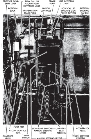
The driver's controls are shown here. The driver was provided with an elevation lever for the bow-mounted .30cal machine gun, and could fire the weapon from his position. The Hycon system provided hydraulic assistance to the driver to help steer the tank. The short Hycon control levers on top of the Hycon control box were normally used; the longer manual steering levers could be used when the Hycon system was inoperative. The M6 was driven without a clutch, but the transmission brake pedal needed to be depressed when changing gears to slow the converter turbine and transmission gears. (Picture from TM 9-721 Heavy Tanks M6 and M6A1.)
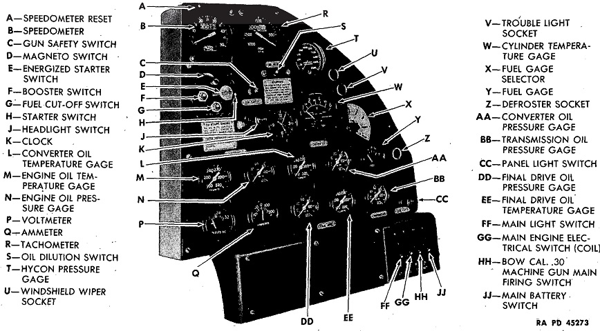
The driver's instrument panel is labeled. (Picture from TM 9-721 Heavy Tanks M6 and M6A1.)
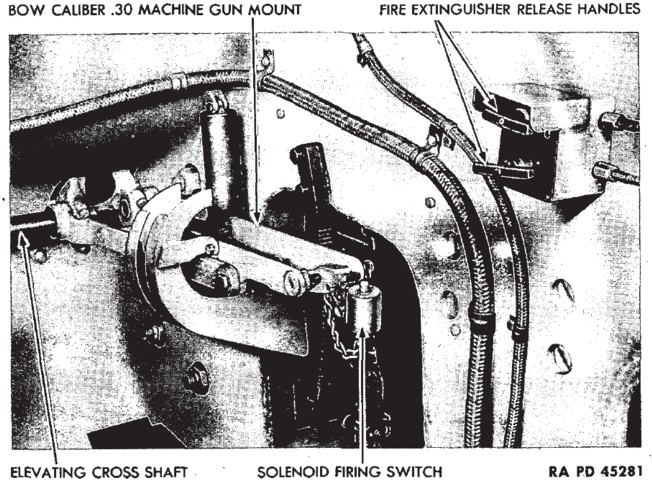
The .30cal bow machine gun was situated in front of the assistant driver. The bow MG could be fired by the assistant driver in emergencies. (Picture from TM 9-721 Heavy Tanks M6 and M6A1.)
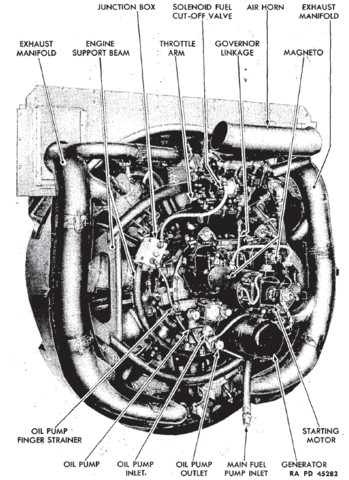
The accessory side of the Wright G-200 is shown here. The engine displaced 1823in³ (29,870cm³) with a bore of 6.125" (15.56cm) and a stroke of 6.875" (17.46cm). Compression ratio was 4.92:1, it weighed 1,350lb (612kg), and was 51.93" (131.9cm) long by 55.07" (139.9cm) in diameter. (Picture from TM 9-721 Heavy Tanks M6 and M6A1.)
The right side of the engine's accessory end is labeled. (Picture from TM 9-721 Heavy Tanks M6 and M6A1.)
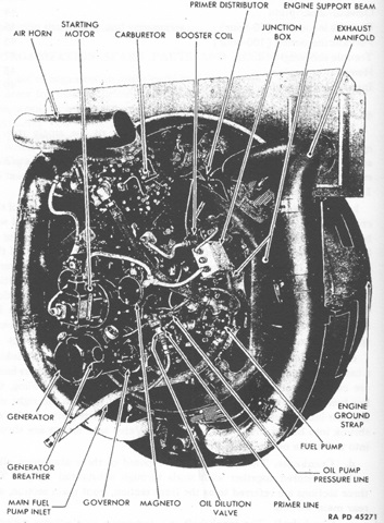
The drive end of the engine is seen in this picture. (Picture from TM 9-721 Heavy Tanks M6 and M6A1.)
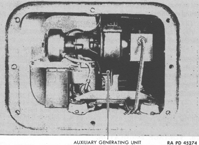
The auxiliary generator was a 2-cycle, 2-volt, single-cylinder, air-cooled, inverted type gasoline engine that ran at 3,500-3,600rpm. This powered a 30-volt, 1,500-watt generator. The unit was mounted in the left rear sponson, and could be accessed from outside through a removable plate in the left track armor or from inside the engine driving compartment. The control box and voltage regulator were in the left rear of the driving compartment. A 6gal (23L) fuel tank was accessed from the top of the hull, and ⅜ pint (180mL) of SAE 40, 50, or 60 engine lubricating oil was to be mixed with each gallon (3.8L) of gasoline. (Picture from TM 9-721 Heavy Tanks M6 and M6A1.)
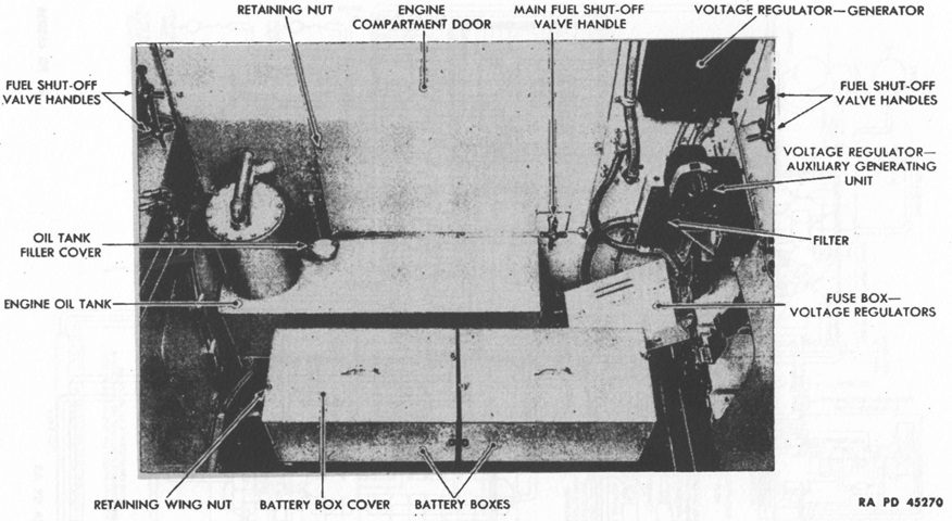
Two 12-volt storage batteries were connected in series to create a 24-volt electrical system. They were mounted in two boxes installed at the rear of the driving compartment. (Picture from TM 9-721 Heavy Tanks M6 and M6A1.)
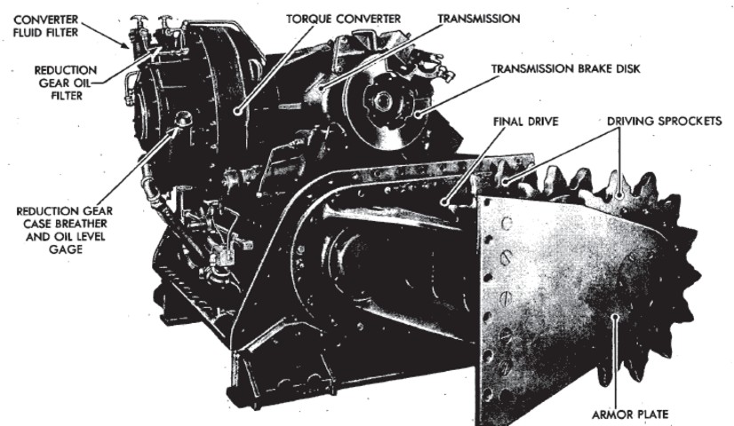
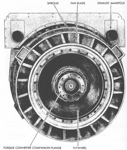
The dismounted torque converter, transmission, and final drive assembly is visible here. The recommended fluid for the torque converter was No. 1 grade diesel fuel. (Picture from TM 9-721 Heavy Tanks M6 and M6A1.)
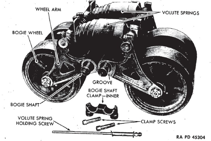
A suspension bogie is the subject of this picture. The tracks on the M6 originally used outside guides, but thanks to the nature of the dual wheels, center guides were able to be installed during testing. (Picture from TM 9-721 Heavy Tanks M6 and M6A1.)
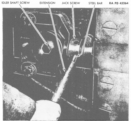
To adjust track tension, lock wires that secured the idler block nuts and cover plate nuts first had to be removed. Then these nuts and the jack screw clamp were loosened, and the cover plate removed. The idler shaft screws were then loosened, and the jack screw was turned in the appropriate direction. There was a jack screw on each side of the dual idler wheel; they were to be alternated between during adjustment in order to prevent misaligning the idler wheel. (Picture from TM 9-721 Heavy Tanks M6 and M6A1.)
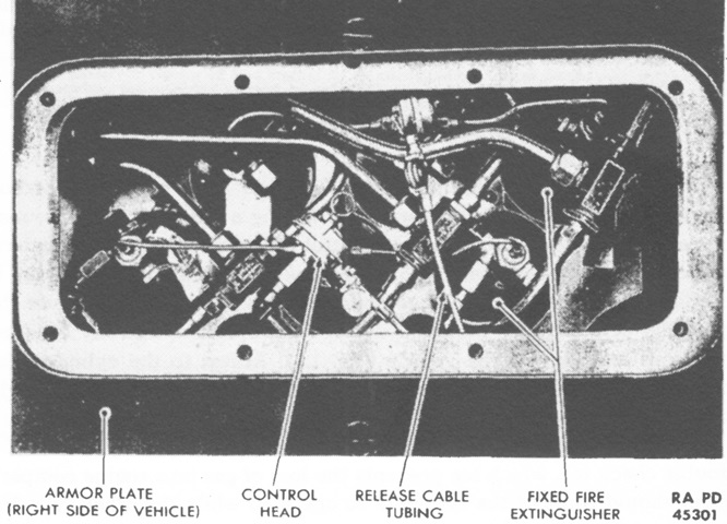
The fire extinguishing system consisted of six 10lb (4.5kg) carbon dioxide cylinders that were routed to suffocate fires in the engine compartment. The cylinders were mounted halfway down the right sponson, and access was available via a removable plate in the track armor. Two release handles were available on the right side of the hull and at the assistant driver's position. Each handle in both locations actuated three cylinders, and the further the handle was pulled, the faster the gas was released. The second handle and group of three cylinders was to provide protection against another fire after the first actuation had been used. In addition, a 4lb (2kg) portable extinguisher was mounted in the turret and in the drivers' compartment. (Picture from TM 9-721 Heavy Tanks M6 and M6A1.)
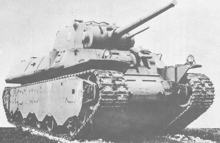
The M6A1 differed principally in that it used a welded instead of cast hull. The sharp-angled joints of the hull plates are apparent. (Picture from Catalogue of Standard Ordnance Items, second edition 1944, volume I: Tank and Automotive.)
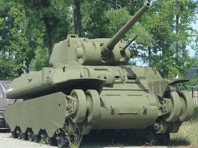
Although externally identical to the M6, the T1E1 was driven by an electric drive system instead of a more conventional transmission. This vehicle is fitted with the center guide T31 tracks. These were made from a set of the outside guide tracks where the center guide replaced the center connector, and the outside guides were removed by flame cutting. Note the partially-open driver's visor on this tank. (Picture from Tank Data, vol. 1.)
The thickness of the armored skirt can be seen here, as well as the engine's exhaust opening. A pistol port can be seen in the turret rear, and an antenna mount is visible in the middle of the turret bustle roof. (Picture courtesy 8Hussar Ottawa.)
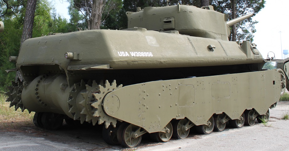
With the tracks removed, a better view is provided of the three sprocket rings used to drive each track. (Picture courtesy Calvin.)
From this angle, the upper adjustable main idler wheels and the lower nonadjustable auxiliary idlers are easily seen. (Picture courtesy Calvin.)
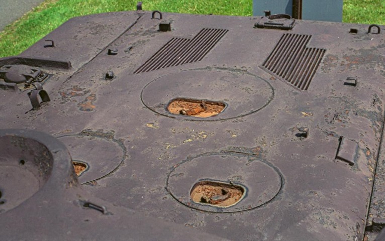
Access hatches and air inlets for the engine and electric transmission are visible on the engine deck. The 3" gun travel lock is mounted at the rear of the deck, and an armored fuel filler cover can be seen to the left of the image. (Picture courtesy 8Hussar Ottawa.)
