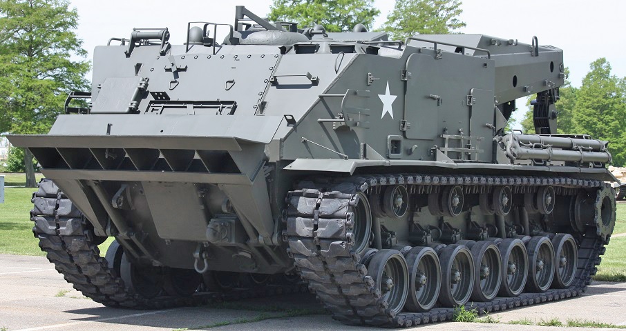
Heavy Recovery Vehicle M51.
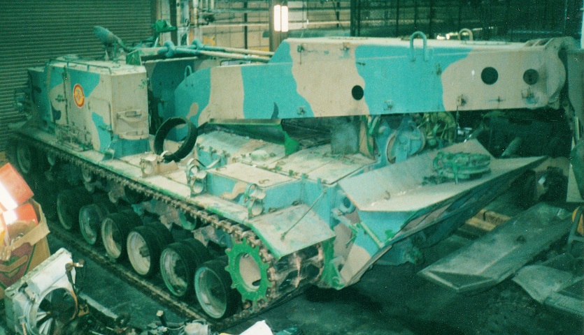
The bulk and miscellany of fixtures on the M51 certainly offered an imposing presence. (Photo by Richard S. Eshleman.)
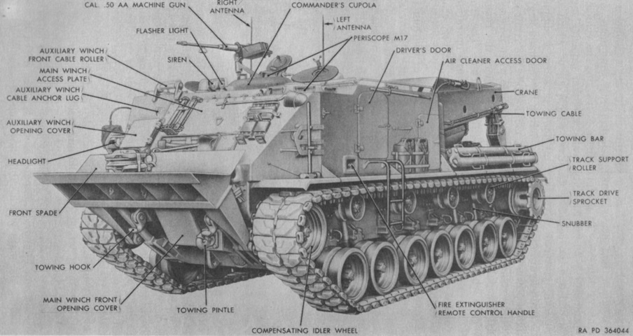
A stepladder can be seen mounted below the driver's door, and a 205lb (93.0kg) heavy duty snatch block is visible stowed in the front spade. Another was stowed in the rear spade. (Picture from TM 9-2320-204-12.)
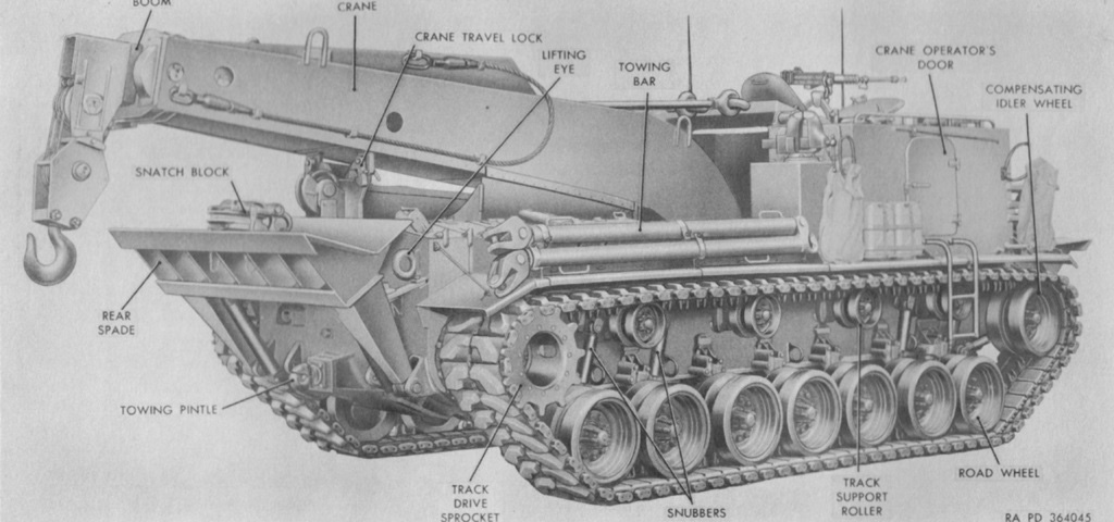
The crane operator's door was also provided with a ladder to ease entry and exit. (Picture from TM 9-2320-204-12.)
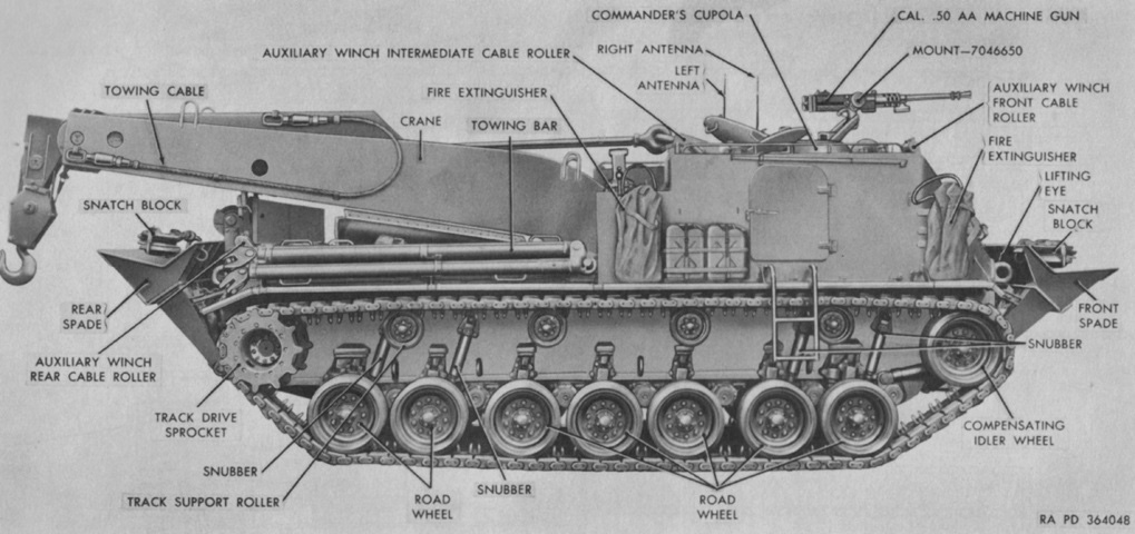
The vehicle is seen in profile in this picture. Two large 15lb (6.8kg) CO2 portable fire extinguishers were stowed on the right fender. (Picture from TM 9-2320-204-12.)
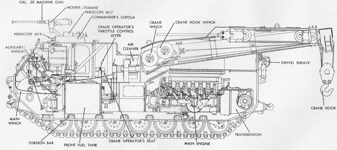
The interior arrangement is detailed in this cross-sectional sketch. (Picture from TM 9-2320-204-12.)
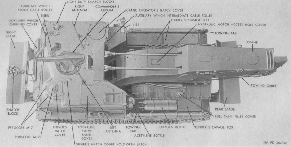
The positions of the driver's, commander's, and crane operator's roof hatches can be seen here, along with the stowage position of the ladders on the left rear corner of the roof. Just to the right of the siren is the unlabeled ventilating blower air intake elbow. (Picture from TM 9-2320-204-12.)
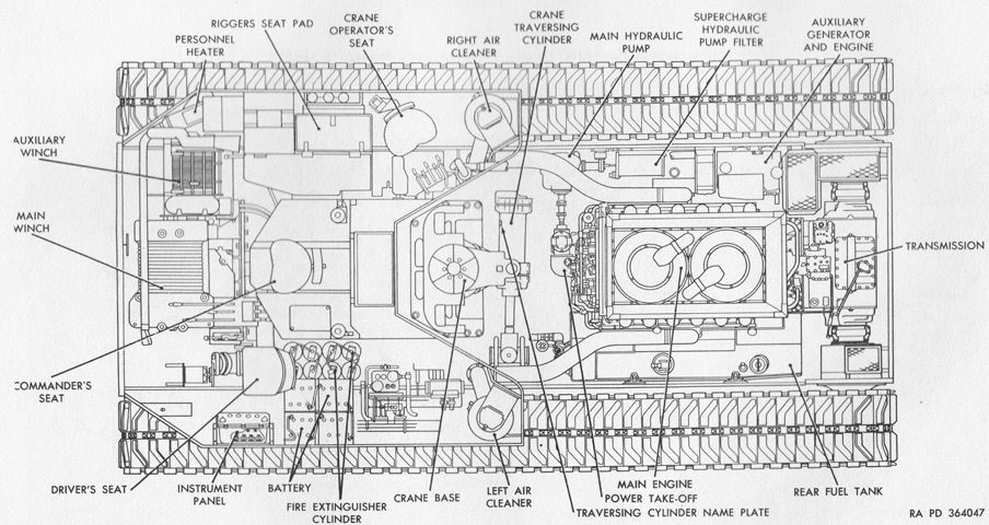
This drawing is a cross-section from above. (Picture from TM 9-2320-204-12.)
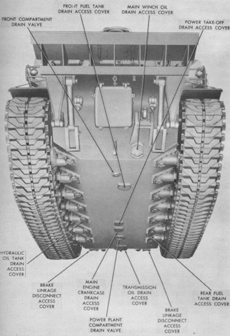
Various openings in the hull bottom are detailed in this image. (Picture from TM 9-2320-204-12.)
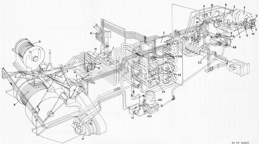
This diagram is of the extensive hydraulic system. A. Main winch hydraulic motor. B. Main winch. C. Auxiliary winch hydraulic motor. D. Auxiliary winch. E. Driver's hydraulic stroking lever. F. Driver's hydraulic control valve. G. Main hydraulic pump filter. H. Crane operator's hydraulic stroking pedal. J. Crane elevation limit valve. K. Crane operator's hydraulic control valve. L. Hydraulic valve panel. M. Main hydraulic pump and stroking valve. N. Supercharge hydraulic pump relief valve. P. Pressure switch. Q. Supercharge hydraulic pump filter. R. Crane winch. S. Crane winch hydraulic motor. T. Crane hook winch. U. Extended boom limit load relief valve. V. Extended crane hook limit load relief valve. W. Crane hook load pilot valve. X. Boom limit load pilot valve. Y. Crane hook winch hydraulic motor. Z. Hydraulic oil tank. AA. Supercharge hydraulic pump. BB. Power-take-off. CC. Traversing cylinder. DD. Traversing cylinder drain valve. EE. Flow control valve. FF. Traversing cylinder relief and replenishing valve. GG. Auxiliary hydraulic powerpack. HH. Auxiliary hydraulic pump relief valve. JJ. Auxiliary hydraulic pump unloading valve. (Picture from TM 9-2320-204-35.)
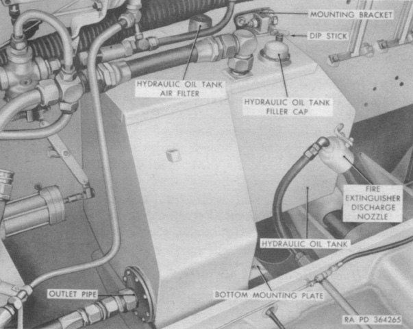
Feeding the hydraulic system was a 35gal (130L) oil tank. The variable-displacement piston pump powering the closed hydraulic circuit was driven by a power takeoff from the main engine. The pump's displacement was controlled by a stroking lever or pedal at the driver's or crane operator's positions, respectively. A supercharge circuit replenished the fluid in the power circuit, supplied pressure to the control circuit, and replenished fluid lost to the drain circuit by the hydraulic motors, cylinder, and valves during periods when they were not being used. A constant-displacement vane pump driven by the power takeoff and drawing fluid from the hydraulic tank pressurized the supercharge circuit. An auxiliary hydraulic circuit driven by an electric constant-displacement vane pump supplied pressurized fluid when the main engine was inoperative. (Picture from TM 9-2320-204-12.)
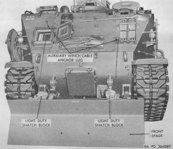
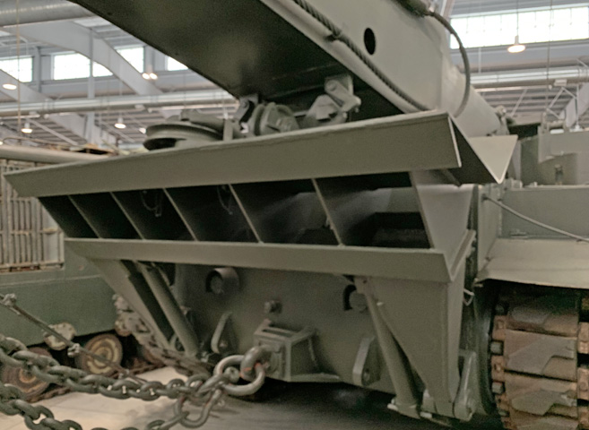
The front and rear spades were to anchor the vehicle when pulling with the main winch to the front or rear, respectively; the rear spade was also used for stabilization when lifting with the crane. The auxiliary winch was used to lower and raise the spades. The spades' attaching brackets were positioned on the hull so that the vehicle would tend to ride up on them, forcing the spade into the ground rather than initiating a bulldozing action, although when the front spade was rigged as shown with light snatch blocks it could be used for clearing operations. (Picture from TM 9-2320-204-12.)
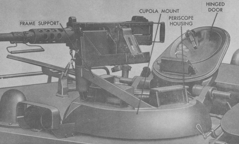
Details of the commander's cupola are shown here. Four unity periscopes M17 were mounted in the cupola, each with a 50° vertical and 150° horizontal field of view, giving the commander a 360° view from inside. (Picture from TM 9-2320-204-35.)
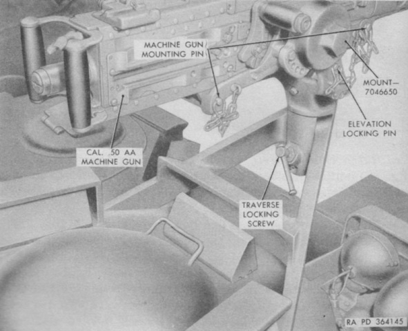
The machine gun mount provided elevation and traverse in addition to the traverse of the cupola. A locking pin and locking screw could secure the mount in elevation and traverse, respectively. (Picture from TM 9-2320-204-12.)

The commander was able to choose between seventeen height settings for his seat, and the seat was able to swing to any of five positions. Two smaller 5lb (2.3kg) CO2 portable fire extinguishers were stowed on the commander's platform. (Picture from TM 9-2320-204-12.)
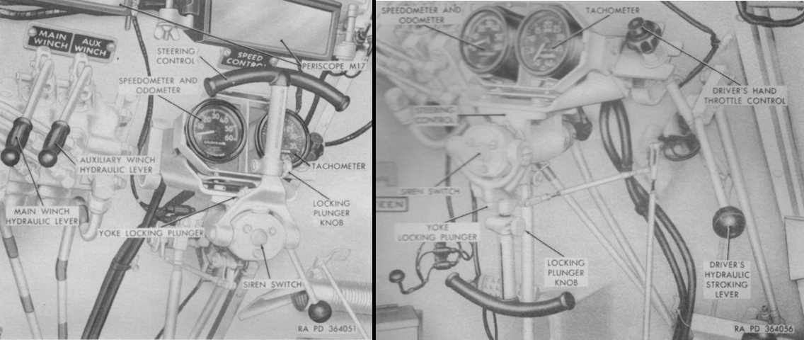
The driver's seat had three height positions, and the steering control could be positioned in a lowered or raised position and also extended to enable the driver to use it in all seating positions as well as when standing. To the driver's front left were the control levers for the main and auxiliary winches. When the main winch hydraulic lever was raised, cable would pay out if the winch was in low gear, but if in high gear the cable would be reeled in. The opposite would occur with the lever lowered. This enabled high and low gears to be used while both paying out and reeling in the cables. The auxiliary winch operated in the same manner. The hydraulic stroking lever varied the output of the main hydraulic pump, and therefore the speed of the main and auxiliary winches. Speed was increased when the lever was raised, and it would return to its normal position when it was released. (Picture from TM 9-2320-204-12.)
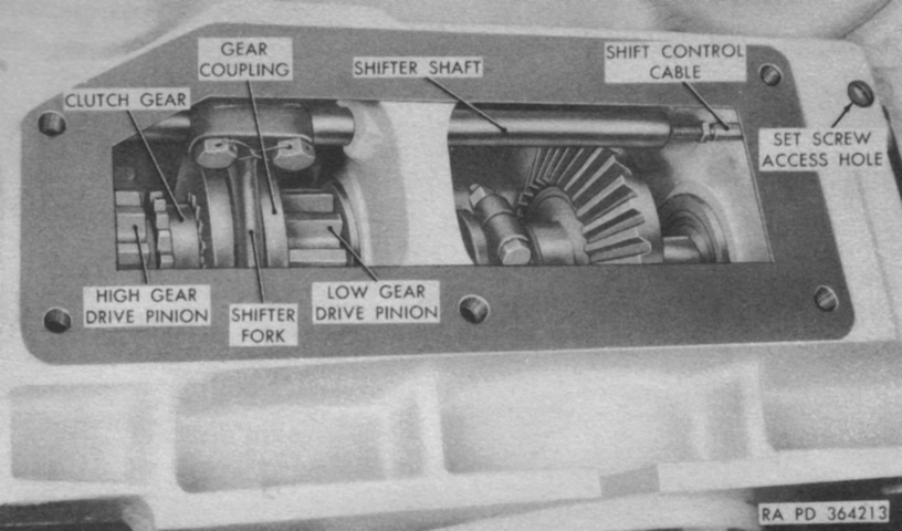
The driver's foot pedals and shifting levers are shown here; the brake pedal can be seen reaching up and to the left at the left edge of the picture. The main winch shift lever was in neutral when centered; high gear was forward and low gear was to the rear. Shifting to the opposite gear would reverse the direction of the winch drum. The brakes for the two winches were activated by pulling their levers to the rear to the degree desired. (Picture from TM 9-2320-204-12.)
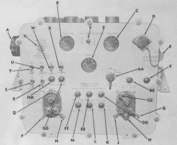
The driver's instrument panel is detailed in this picture. A. Auxiliary power receptacle. B. Rear fuel tank gage. C. Front fuel tank gage. D. Accessory outlet socket. E. Master switch. F. Master switch indicator light. G. Main engine starter switch. H. Fuel cutoff switch. J. Booster switch. K. Main engine oil high temperature warning light. L. Transmission oil high temperature warning light. M. Auxiliary engine generator warning light. N. Release lever. P. Instrument panel lamp rheostat lever. Q. Driving lights selector switch. R. Personnel heater master switch. S. Ventilating blower switch. T. Bilge pump switch. U. Power plant heater switch. V. External voltage control rheostat plug. W. Infrared power switch. X. Flasher light control switch. Y. Fuel tank selector switch. Z. Main engine oil pressure gage. AA. Auxiliary engine magneto switch. BB. Auxiliary engine low oil pressure warning light. CC. Main engine magneto switch. DD. Main engine oil low pressure warning light. EE. Transmission oil low pressure warning light. FF. Main engine generator warning light. GG. Flasher indicator light. HH. Infrared power indicator light. (Picture from TM 9-2320-204-12.)
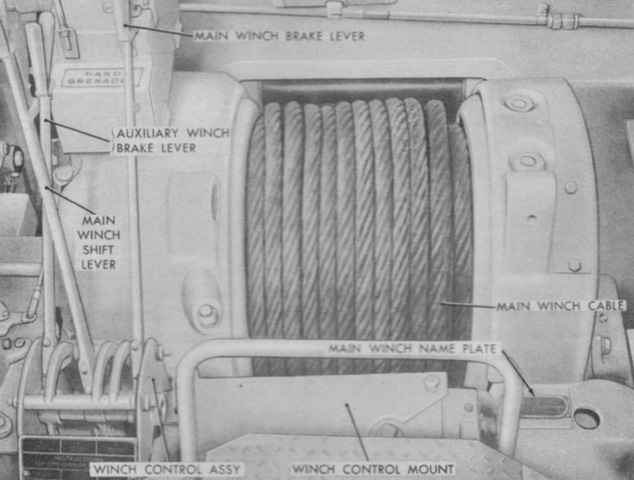
The position of the main winch relative to the driver can be divined from the position of the previously-seen levers to the left. It was chain-driven by a constant displacement hydraulic motor on the hull's left side. High gear was a 26.3:1 reduction, while low gear was 45.2:1. Maximum line pull in low gear was 90,000lb (41,000kg) at 25fpm (7.6mpm) with the drum empty or 44,000lb (20,000kg) at 52fpm (16mpm) with the drum full. (Picture from TM 9-2320-204-12.)
The main winch is shown here with its top cover plate removed. (Picture from TM 9-2320-204-12.)
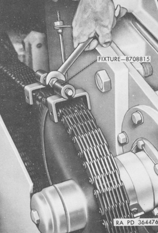
The chain drive for the main winch is visible looping around the driven sprocket. Fixture 8708815 was used to remove the chain. (Picture from TM 9-2320-204-35.)
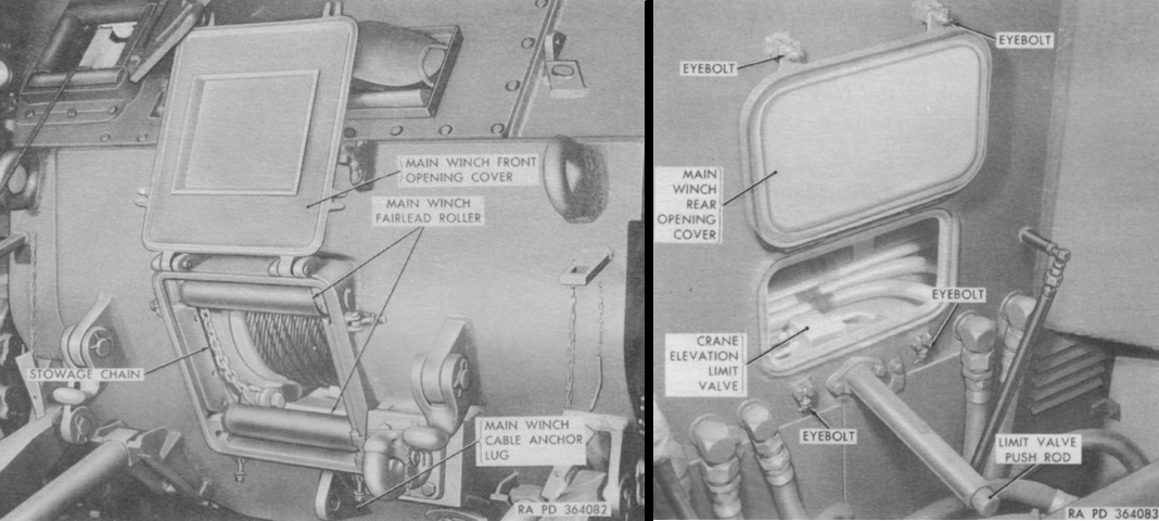
The main winch front and rear opening covers can be seen in these pictures. To access the front opening, the spade needed to be lowered, then a crewman would press against the cover to take the weight off of the four eyebolts with hex nuts that secured it. The upper two eyebolts had clips to hold them out of the way when the cover was opened or closed, and a hold-open latch held the cover in the raised position. The rear opening cover was secured closed with two eyebolts and threaded nuts, and when opened a second set of eyebolts with hex nuts held the cover up. (Picture from TM 9-2320-204-12.)
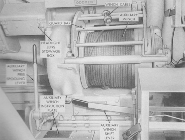
The shift lever for the auxiliary winch was mounted horizontally on the rear of that winch. Lowering the lever engaged high gear, while raising it engaged low gear. High gear reduction was 21.2:1, while low gear was 29.7:1. The winch drum could be disengaged and allowed to run free by pushing the free spooling lever forward. (Picture from TM 9-2320-204-12.)
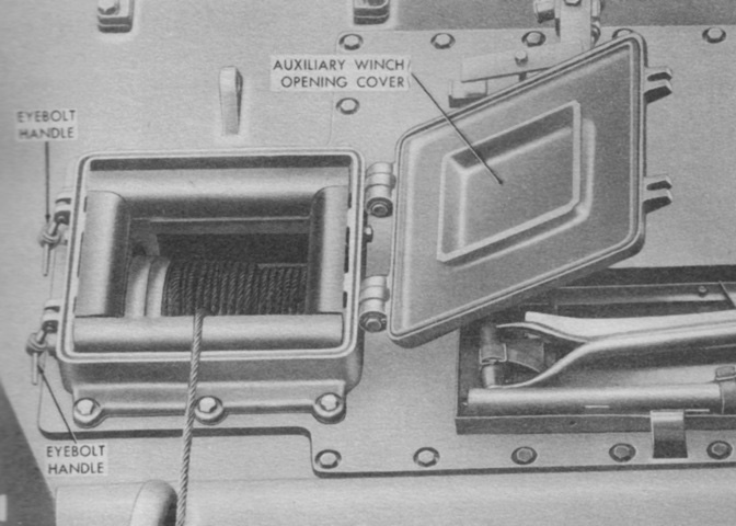
The auxiliary winch opening cover was secured by two eyebolts with threaded handles. (Picture from TM 9-2320-204-12.)
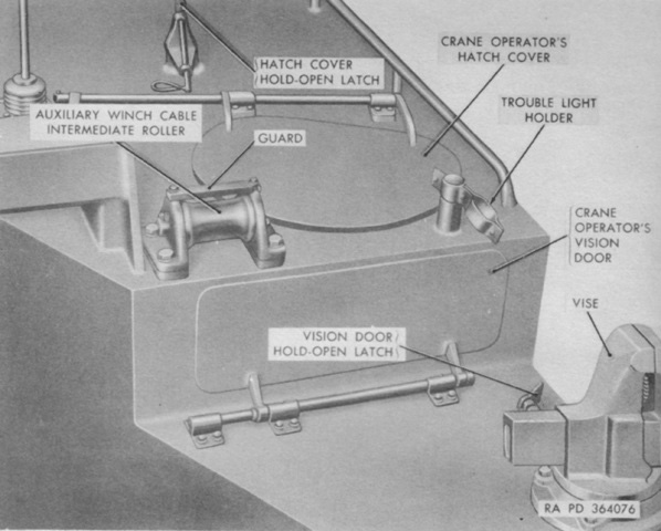
The crane operator had a roof hatch and a vision door that opened to the rear so that he could monitor his work. (Picture from TM 9-2320-204-12.)
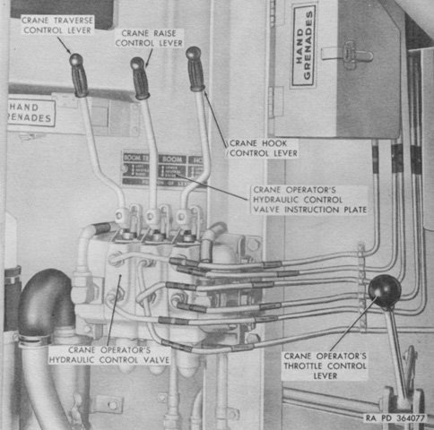
The crane operator's vision door can be seen in the upper left corner of this image. The throttle control lever to the lower right of the picture would increase engine speed when pulled down and reduce engine speed when pushed up. This lever retained its position when released. The crane traverse control lever traversed the crane to the right of the vehicle when pulled toward the operator, and vice-versa. The crane raise control lever elevated the crane when pulled toward the operator and lowered the crane when pushed away. The hook control lever raised the hook when pulled toward the operator, and lowered the hook when pushed away. All three of these levers centered themselves when released. (Picture from TM 9-2320-204-12.)
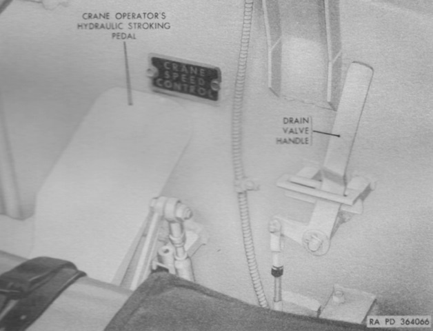
The crane operator's drain valve handle controlled the hull drain valve in the powerplant compartment. The valve was opened by pulling the handle outboard and forward, and closed by pulling outboard and rearward. It was pushed inboard to lock. The hydraulic stroking pedal controlled the speed of crane operations by changing the stroke length of the pistons in the main hydraulic pump and thereby changing its output. The pedal returned to the released position when foot pressure was gone, and could be locked into the released position via a lock handle at the pedal's bottom left. (Picture from TM 9-2320-204-12.)
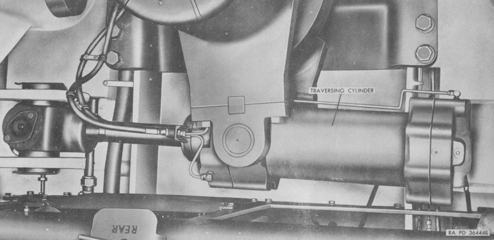
The double-acting crane traversing cylinder was mounted by trunnions on the rear of the crane support. The end of the traversing cylinder piston rod was secured to the left side of the hull. (Picture from TM 9-2320-204-35.)
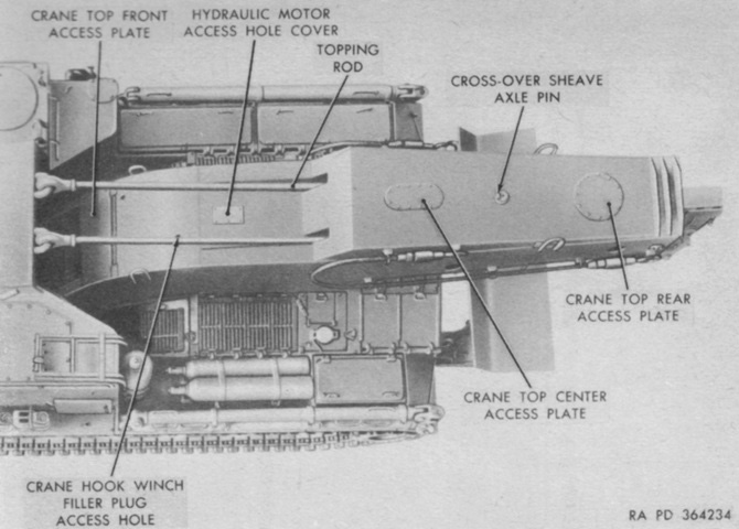
Features of the top of the crane are labeled in this picture. (Picture from TM 9-2320-204-12.)
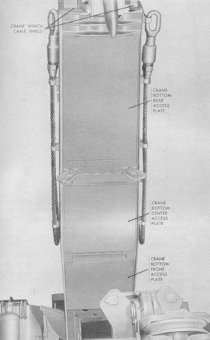
Access plates in the bottom of the crane can be seen here. (Picture from TM 9-2320-204-12.)
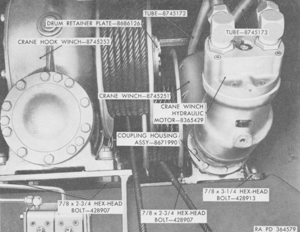
The crane was actuated by two hydraulic winches. One raised and lowered the crane as well as extended the boom, and the other raised and lowered the hook and retracted the boom. (Picture from TM 9-2320-204-35.)
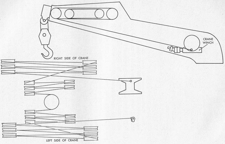
Reaving of the crane winch cable is diagrammed here. The topping rods ended in blocks attached to the front sheave assemblies. (Picture from TM 9-2320-204-12.)
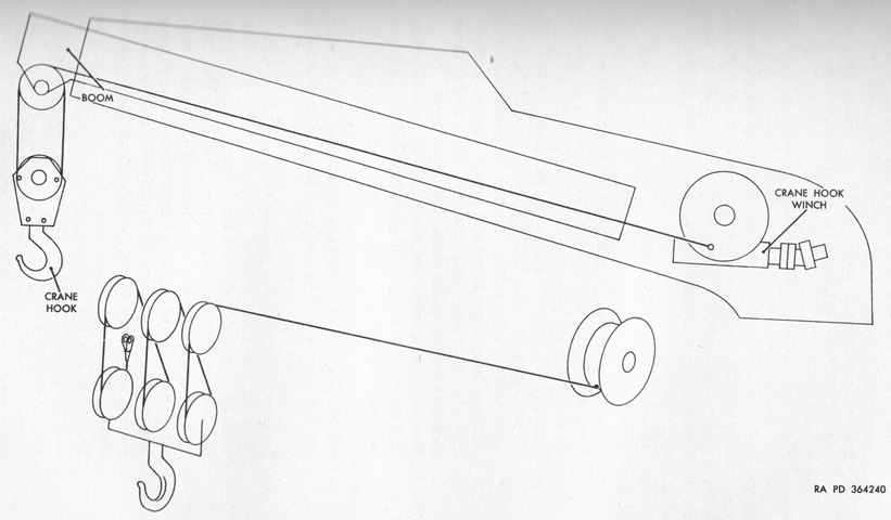
The crane hook cable reaving diagram is provided here. (Picture from TM 9-2320-204-12.)
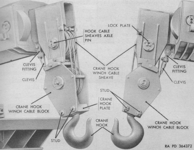
Both sides of the crane hook and its cable sheaves are labeled in this picture. (Picture from TM 9-2320-204-12.)
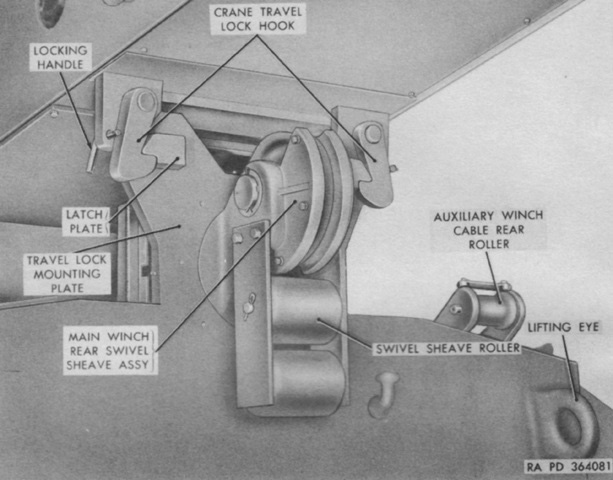
A travel lock secured the crane during movement. The travel lock was released by pulling the locking handles forward through the mounting plates and then rotating the hooks away from the latch plates. The locking handles could then be pushed back through their mounting plates to hold the hooks in the disengaged position. (Picture from TM 9-2320-204-12.)
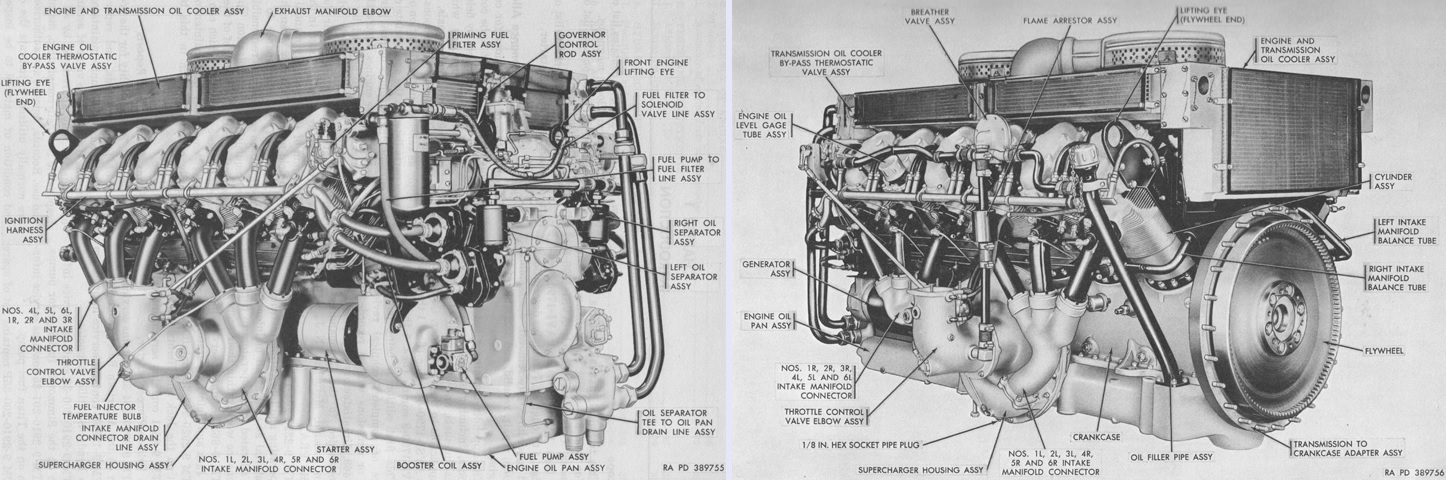
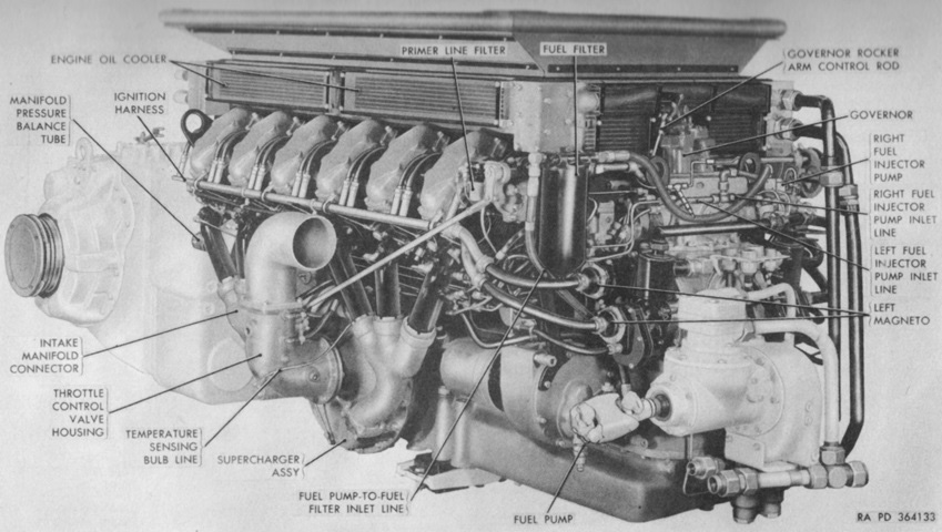
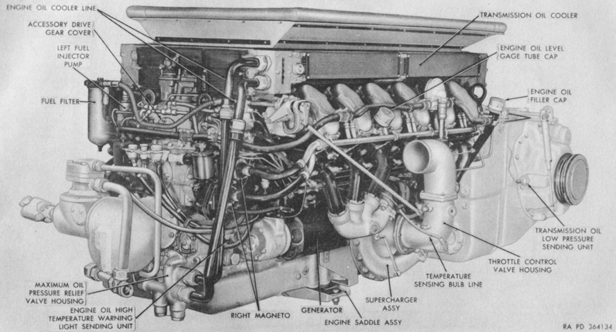
The AVSI-1790-6 engine is shown from the left front on the left and the right rear on the right. The engine was 72.83" (185.0cm) long, 56.74" (144.1cm) wide, and 45.68" (116.0cm) tall. Bore and stroke were both 5.75" (14.6cm) for a displacement of 1,790in³ (29.3L). The compression ratio was 5.5:1, and dry weight with accessories was 3,050lb (1,380kg). The accessory end was considered the front, and the right and left sides were determined by looking at the engine from the accessory end to the flywheel end. Cylinders were numbered 1-6 on each side starting at the accessory end, and firing order was 1R, 2L, 5R, 4L, 3R, 1L, 6R, 5L, 2R, 3L, 4R, and 6L. (Picture from TM 9-2805-206-35.)
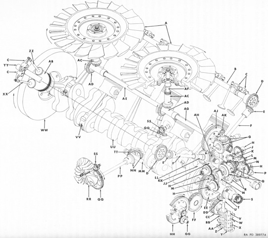
The engine's gear train and major component parts are diagrammed in this sketch. A. Cooling fan rotor and clutch assembly. B. Right camshaft assembly. C. Valve rocker and adjusting screw assembly. D. Camshaft driven bevel gear. E. Upper camshaft drive quill bevel gear. F. Camshaft drive quill. G. Fuel injector pump driven bevel shaftgear. H. Magneto drive driven gear. J. Tachometer drive driven idler shaft gear. K. Tachometer drive driven shaft gear. L. Magneto drive gear assy. M. Magneto and spark advance governor drive shaft. N. Spark advance governor assembly. P. Generator drive shaft assembly. Q. Spark advance governor drive bevel gear. R. Generator drive idler gear assembly. S. Accessory drive crankshaft extension shaft. T. Oil pump drive bevel gear. U. Oil pump driven bevel gear. V. Oil pump driven impellers idler shaft. W. Oil scavenge pump driven impeller. X. Oil pressure pump driven impeller. Y. Oil level control pump driven impeller. Z. Oil level control pump drive impeller. AA. Oil pressure pump drive impeller w/integral shaft. BB. Oil scavenge pump drive impeller. CC. Supercharger impeller drive idler gear. DD. Impeller drive idler spur gear assembly. EE. Accessory drive gear and shaft assembly. FF. Starter idler gear assembly. GG. Fuel pump drive gear. HH. Starter and fuel pump drive gear and hub assembly. JJ. Accessory drive driven shaft gear. KK. Crankshaft damper counterweight. LL. Lower camshaft drive quill bevel shaftgear. MM. Supercharger impeller main drive shaft. NN. Supercharger impeller drive driven bevel gear. PP. Left impeller drive shaft. QQ. Impeller drive spur gear. RR. Supercharger impeller. SS. Supercharger impeller driven shaftgear. TT. Supercharger impeller drive bevel gear. UU. Crankshaft assembly. VV. Connecting rod and cap assembly. WW. Flywheel. XX. Intake valve. YY. Left camshaft assembly. ZZ. Exhaust valve. AB. Piston. AC. Fan drive driven shaftgear. AD. Fan drive bevel shaftgear. AE. Rear horizontal fan drive shaft. AF. Vertical fan drive shaft. AG. Front horizontal fan drive shaft assembly. AH. Camshaft drive bevel gear. AJ. Fuel injector pump drive shaftgear assembly. AK. Governor drive bevel gear. (Picture from TM 9-2805-206-35.)
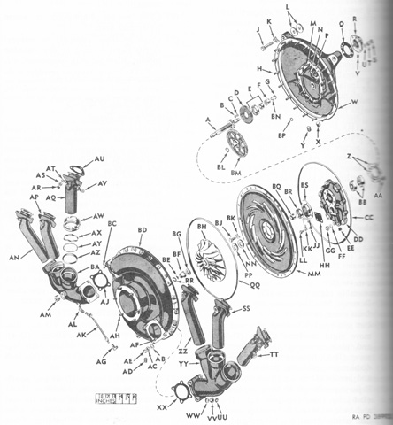
An exploded view of the left intake manifold connectors, tubes, and supercharger assembly is drawn. The supercharger impeller ran at 7.86 times the crankshaft speed. A. Supercharger impeller drive shaftgear. B. 5/16 hexagon slotted nut. C. 21/64 id, 9/16 od, 1/16 thk flat washer. D. Roller bearing retaining plate. E. Supercharger impeller driven shaft gear roller bearing. F. Supercharger impeller locking nut. G. 13/16 od locking ring. H. 5/16 x 1-15/16 stud. J. 7/16 x 2-19/64 machine bolt. K. 15/32 tab washer. L. Supercharger drive housing mounting spacers and shims. M. 5/16 x 1-15/16 stud. N. 5/16 x 1⅛ stud. P. 5/16 x 5/18 headless straight pin. Q. Shaftgear cover gasket. R. Shaftgear cover. S. 5/16 stamped nut. T. 5/16 hexagon plain nut. U. 21/64 id, 9/16 od, 1/16 thk flat washer. V. ⅛ pipe plug. W. Supercharger impeller drive housing assembly. X. ⅛ pipe plug. Y. ¼ pipe plug. Z. Ball bearing retaining plate. AA. ¼ x 17/32 machine bolt. BB. Supercharger impeller driven shaft gear ball bearing. CC. 16" id x 9/64 thk "O" ring packing. DD. Supercharger impeller drive diaphragm assembly. EE. ⅛ pipe plug. FF. 21/64 id, 9/16 od, 1/16 thk flat washer. GG. 5/16 hexagon slotted nut. HH. Drive shaft cover gasket. JJ. Drive shaft cover. KK. ¼ tab washer. LL. ¼ x 25/32 machine bolt. MM. Supercharger diffuser. NN. Supercharger impeller spacer washer. PP. Supercharger impeller shim. QQ. 16" id x 9/64 thk "O" ring packing. RR. 13/16 od locking ring. SS. Nos. 2R, 5R, 2L, and 5L intake manifold connector tube. TT. No. 1L intake manifold connector tube. UU. 5/16 stamped nut. VV. 5/16 hexagon plain nut. WW. 21/64 id, 9/16 od, 1/16 thk flat washer. XX. Intake manifold connector gasket. YY. Nos. 1L, 2L, 3L, 4R, 5R, and 6R intake manifold connector. ZZ. Nos. 4R and 3L intake manifold connector tube. AB. 21/64 id, 9/16 od, 1/16 thk flat washer. AC. 5/16 hexagon plain nut. AD. ⅛ pipe plug. AE. 5/16 stamped nut. AF. 5/16 x 1⅝ stud. AG. ¼ tube, ⅛ pipe, 90° elbow. AH. 5/16 x 1½ stud. AJ. Intake manifold connector gasket. AK. Intake manifold connector drain line assembly. AL. ¼ tube, ⅛ pipe, 90° elbow. AM. ¾ pipe plug. AN. No. 6L intake manifold connector tube. AP. Nos. 2R, 5R, 2L, and 5L intake manifold connector tube. AQ. Nos. 3R and 4L intake manifold connector tube. AR. 5/16 stamped nut. AS. 5/16 hexagon plain nut. AT. 21/64 id, 9/16 od, 1/16 thk flat washer. AU. Intake manifold connector tube gasket. AV. ¼ pipe plug. AW. Intake manifold connector tube sealing nut. AX. Intake manifold connector tube sealing spring. AY. Intake manifold connector tube sealing washer. AZ. 2-7/32 id x 13/64 thk "O" ring packing. BA. Nos. 4L, 5L, 6L, 1R, 2R, and 3R intake manifold connector. BC. 5/16 x 1⅝ stud. BD. Supercharger housing assembly. BE. Supercharger impeller nut lock. BF. Supercharger impeller locking nut. BG. 41/64 id, 1⅛ od, 3/32 thk flat washer. BH. Supercharger impeller. BJ. ¼ x 25/32 machine bolt. BK. ¼ tab washer. BL. 55/64 od snap ring. BM. Supercharger impeller drive spur gear. BN. Supercharger impeller nut lock. BP. 5/16 x ⅙ thk "O" ring packing. BQ. Supercharger impeller spacer. BR. Supercharger impeller gear oil seal. BS. Supercharger impeller driven shaftgear oil seal housing. (Picture from TM 9-2805-206-35.)
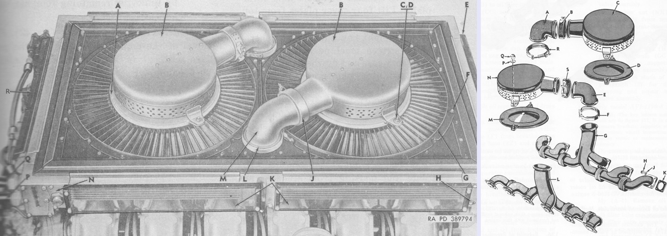
The exhaust mufflers and manifolds are shown mounted on the left and in exploded form on the right. The legend for the left image is: A. Insulator. B. Muffler. C. ⅜ nut. D. Washer. E. Flywheel end screen. F. 5/16 nut. G. Housing assy. H. Bracket. J. Muffler clamp assy. K. Side screen. L. Exhaust clamp assy. M. Elbow. N. Bracket. P Outlet elbow assy. Q. Inlet elbow assy. R. Screen assy.
The legend for the right image is: A. Exhaust manifold elbow. B. Exhaust manifold elbow-to-exhaust muffler clamp assembly. C. Exhaust muffler. D. Exhaust manifold insulator. E. Exhaust manifold elbow. F. Exhaust manifold elbow-to-exhaust manifold clamp assembly. G. Exhaust manifold assembly. H.⅜ hexagon self-locking nut. J. 25/64 id, ⅝ od, 7/64 thk flat washer. K. Exhaust manifold mounting gasket. L. Exhaust manifold assembly. M. Exhaust manifold insulator. N. Exhaust muffler. P. 25/64 id, ⅞ od, 3/32 thk flat washer. Q. ⅜ hexagon self-locking nut. R. Exhaust manifold elbow-to exhaust manifold clamp assembly. S. Exhaust manifold elbow-to-exhaust muffler clamp assembly. (Picture from TM 9-2805-206-35.)

The full-throttle power curves for an engine equipped with cooling fans, air cleaners, and mufflers are plotted for gross performance (solid line) and net performance after accessory losses (dashed line) with horsepower on the Y axis and engine rpm on the X axis. The data was corrected to 29.92 inHG (1 atm) dry barometric pressure and 60°F (16°C). (Picture from TM 9-2805-206-35.)
The assembled engine and transmission are shown here. (Picture from TM 9-2320-204-12.)
The transmission and engine are seen from the opposite side. (Picture from TM 9-2320-204-12.)
The XT-1400-2A was a combined transmission, steering, and output reduction drive. Its characteristics included an hydraulic torque converter, disc brakes, split torque drive, and variable steering. When not in lockup, it could vary output torque to the drive sprockets automatically according to the driven-load conditions. (Picture from TM 9-2320-204-12.)
The transmission is mounted to the engine here. It was 42" (110cm) long, 31.75" (80.65cm) tall, and 82.875" (210.50cm) wide between the sides of the vehicle hull. It weighed 6,525lb (2,960kg) dry. (Picture from TM 9-2320-204-12.)
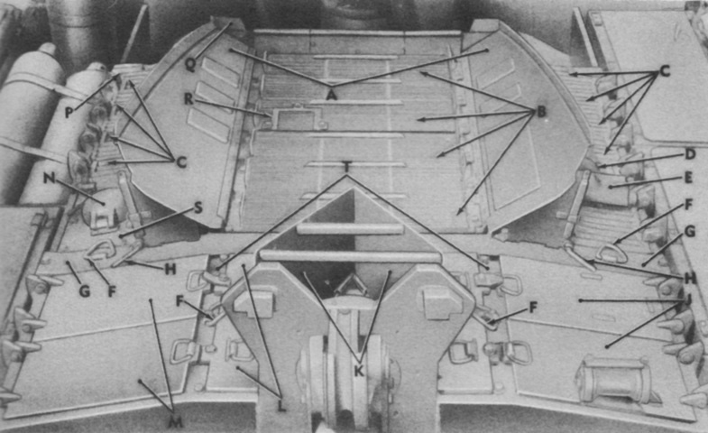
Components of the top deck grille are labeled in this picture. A. Heat deflectors. B. Engine access center grille door. C. Engine access side grille doors. D. Auxiliary engine exhaust tube. E. Auxiliary engine exhaust muffler. F. Lifting eye. G. Rear cross beam. H. Heat deflector retaining pin. J. Transmission access right door. K. Exhaust deflector. L. Transmission access center door. M. Transmission access left door. N. Rear fuel tank fuel filler cap access cover. P. Front cross beam. Q. Heat deflector support plate. R. Access cover. S. Rear fuel tank access door. T. Transmission access door beam. (Picture from TM 9-2320-204-12.)
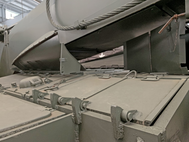
The heat and exhaust deflectors underneath the stowed crane boom are highlighted here.
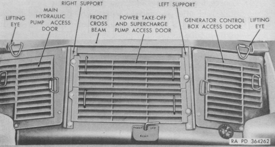
The front section of the top deck grille is shown here. Below the power take-off and supercharge pump access door is the accessory fuel line selector valve handle, which allowed the fuel supply for the auxiliary engine to be fed from either the front or rear fuel tanks, or else cut off. The rotary knob to the lower left is the fuel tank transfer valve handwheel which, when opened, allowed fuel to flow into the front tank when the rear tank was being filled. (Picture from TM 9-2320-204-12.)
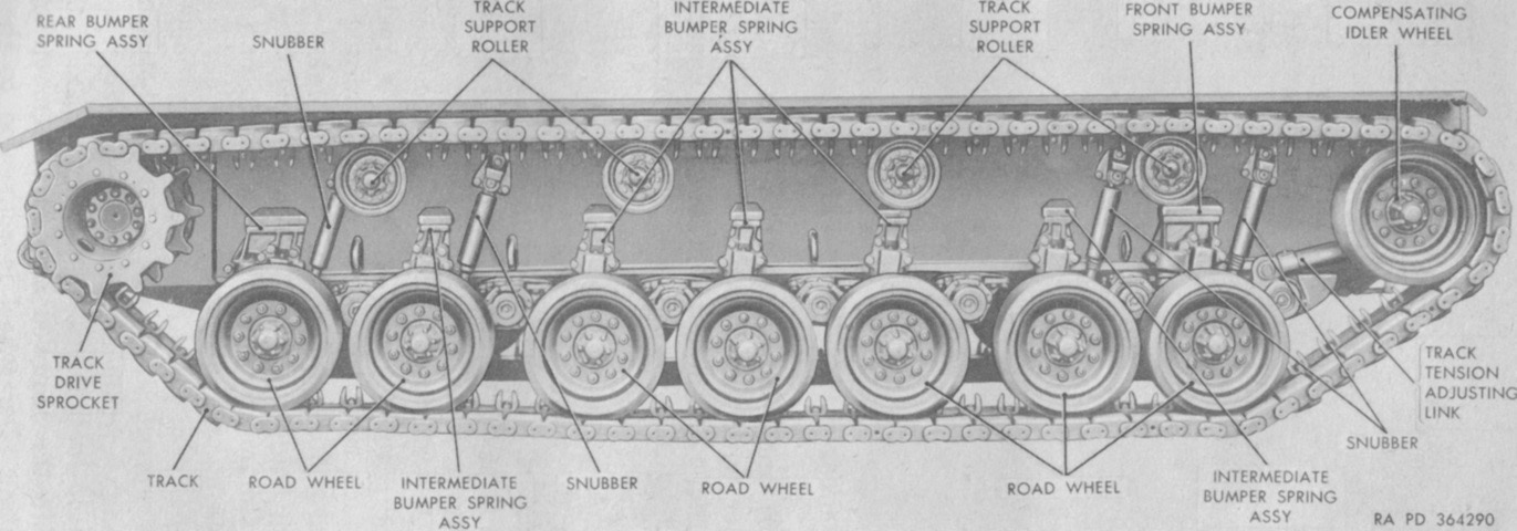
Nomenclature of the running gear is given in this image. (Picture from TM 9-2320-204-12.)
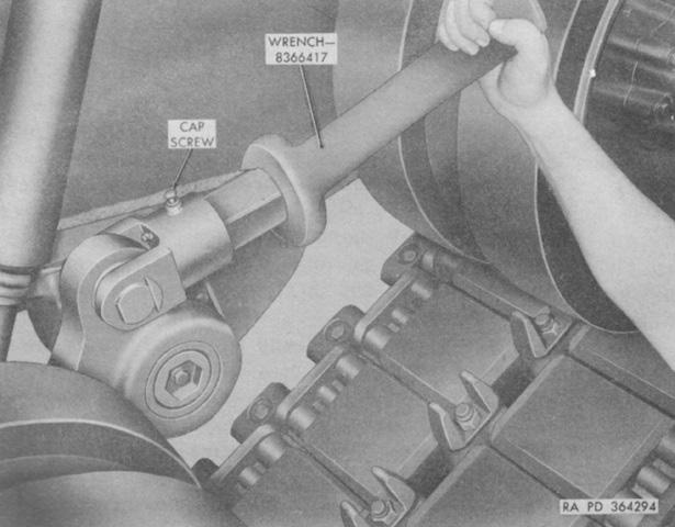
To adjust track tension, the cap screw on the track tension adjusting link was loosened, then the track tension adjusting link was turned clockwise (looking toward the vehicle rear) to increase and counterclockwise to decrease tension. (Picture from TM 9-2320-204-12.)
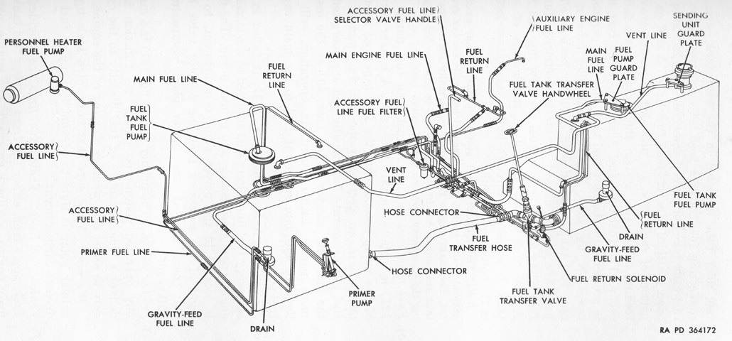
Fuel was stored in two tanks, one in the left side of the power plant compartment, and one under the commander's platform. (Picture from TM 9-2320-204-12.)
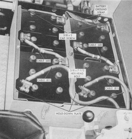
Under the left side floor plate of the cab, four 12-volt, 100-ampere-hour batteries were connected in series parallel, yielding a 24-volt, 200-ampere-hour source. (Picture from TM 9-2320-204-12.)
The auxiliary engine was a General Motors A-41-2 1-cylinder, 4-cycle, constant-speed, air-cooled, 15-horsepower gasoline engine with a bore and stroke of 3.625" (9.208cm) and 4" (10cm), respectively. The engine was mated to a 300-amp, 28-volt generator. The engine's air intake duct can be seen on the opposite side. (Picture from TM 9-2320-204-12.)
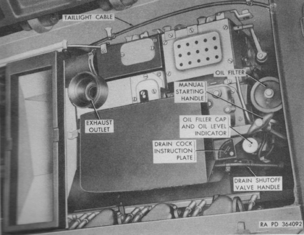
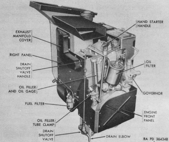
The auxiliary engine is shown installed. Engine speed was governed to 3,100rpm at full load. The engine could be started electrically or manually, and was fed from the main engine fuel supply. (Picture from TM 9-2320-204-12.)
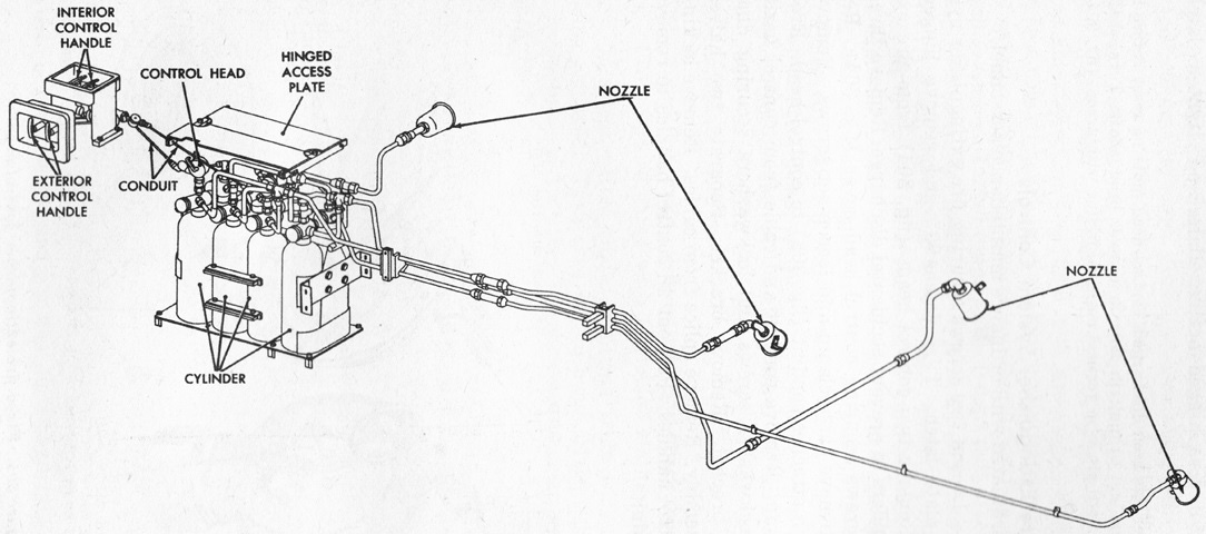
The fixed fire extinguisher system used eight 10lb (4.5kg) CO2 cylinders mounted on a rack to the left rear of the driver's seat. The cylinders were routed to four nozzles, one near the left front fuel tank and the other three in the engine compartment. The cylinders were expended in two shots of four cylinders apiece. The system could be activated by handles to the driver's left rear, by the controls on each set of cylinders, or by two handles on the hull exterior left side. (Picture from TM 9-2320-204-12.)
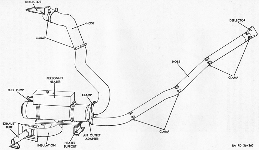
A schematic of the personnel heater is drawn here. The Perfection E500-24 heater produced 60,000BTU/hr on high and 30,000BTU/hr on low. The heater burned gasoline taken from the vehicle fuel supply. (Picture from TM 9-2320-204-12.)
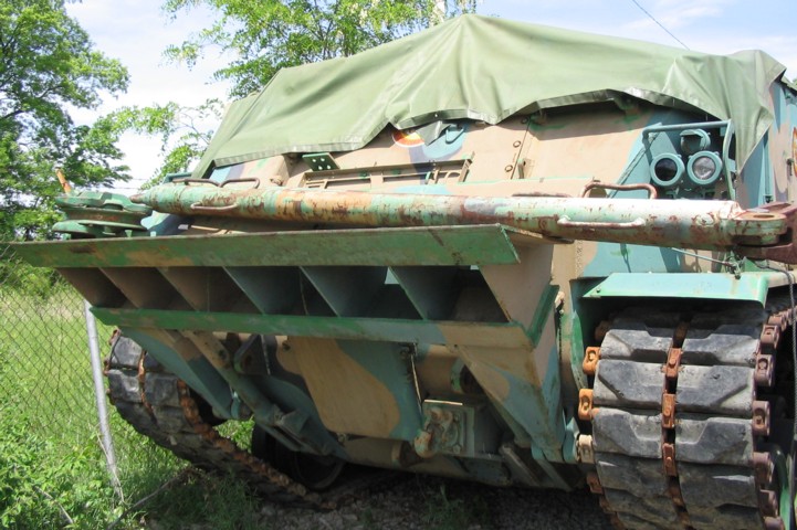
This rear 3/4 view of an M51 recovery vehicle shows the large crane boom and rear stabilizing spade. The running gear is one place to view the vehicle's lineage from the 120mm gun tank M103. A snatch block is resting on the vehicle's rear spade, and visible along the bottom of the crane boom are hooks for stowage of a towing cable. Beside the rear fender stowage box are mounts for stowing a towing bar. Oxygen bottles were placed horizontally in front of this stowage box, and an acetylene bottle was normally stored on the cab's left rear face. Engine access grille doors are visible below the crane boom, and heat deflectors protect the crane boom from damage from engine exhaust. The mount for the commander's .50cal machine gun can be seen in the center of the cab roof.
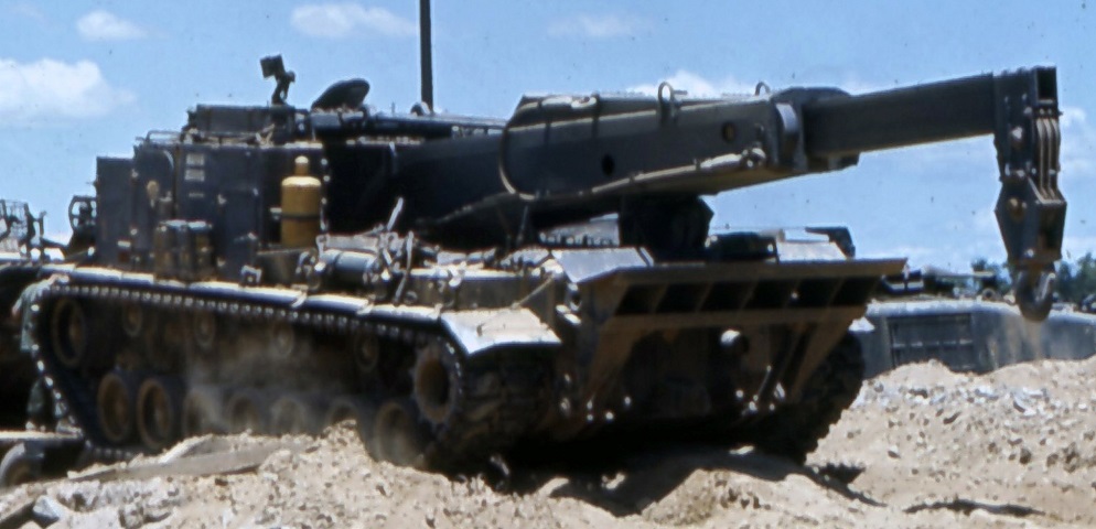
Stowage details can be gleaned from this in-service vehicle. Note the extended crane boom. (Picture taken 1 December 1967; available from the National Archives.)
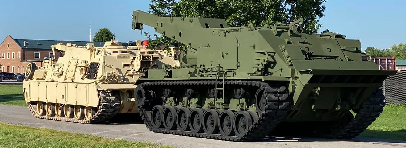
The M51's size can be compared here to an M88A2 HERCULES. (Photo courtesy Josh Hohensee.)

The two vehicles are seen here in profile as the M51 is placed on its plinth. (Photo courtesy Josh Hohensee.)
Although covered by a tarp, much of this M51 is still visible. A towing bar and a snatch block are resting in this vehicle's front spade. A towing pintle is visible beneath the spade, and an empty tool rack is attached to the cab front above the spade.
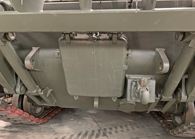
This view beneath the front spade shows the connections of the spade itself as well as the large square main winch front opening cover. The vehicle has a single towing pintle on the front, and lugs for towing hooks are placed above the pintle just inside the spade supports and below the main winch front opening cover. The small round plate below the towing pintle is the main winch oil drain access cover.
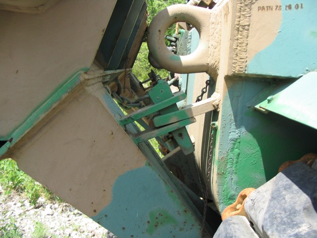
This image slows the front stabilizing spade in its stowed position, secured by cotters. Lifting eyes are welded to each front corner of the vehicle's cab.
The sturdy construction of the rear spade and towing pintle are obvious in this image. The taillights are visible on the hull rear protected by semicircular guards.
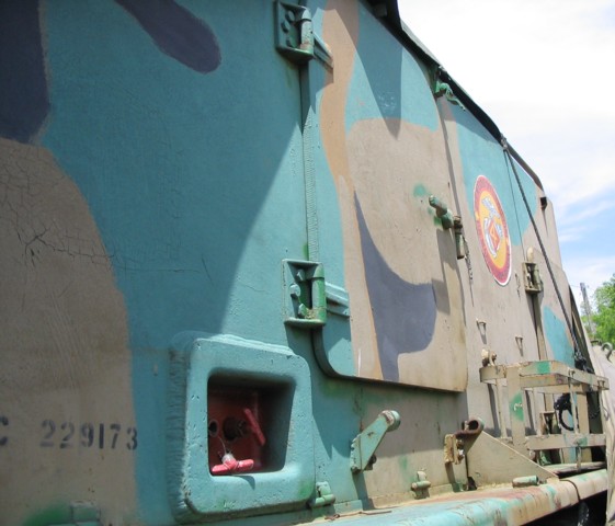
This side of the cab is home to the large door for the driver. The two protuberances just below the driver's door are the mounts for a ladder to assist entry and exit. A closer look is provided of fire extinguisher remote control handles. On the opposite side of the cab, the crane operator had a door and ladder similar to the driver's.
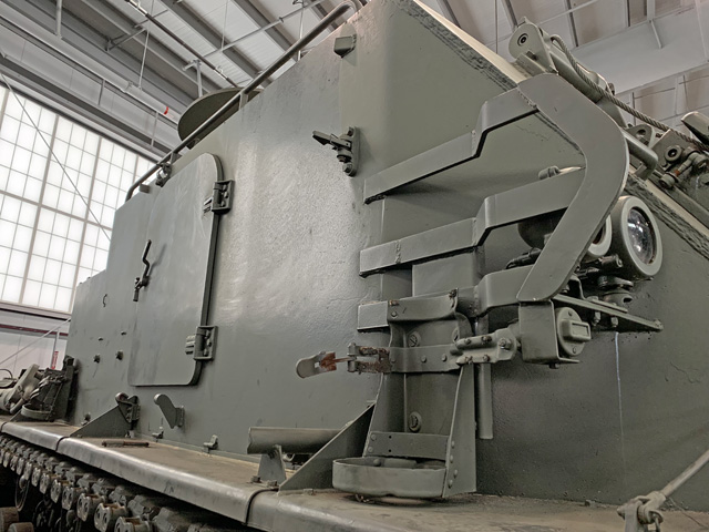
The crane operator's door is seen here, with mounts for the large fire extinguishers on the fender at the front and rear corners of the cab.
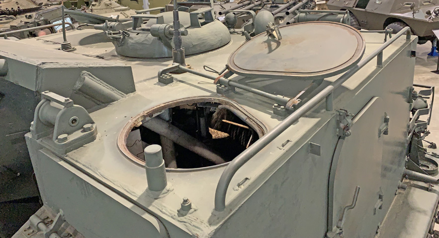
The crane operator's hatch cover is open on this machine. The commander's cupola is in the center of the roof, and the driver's open hatch cover can be seen at the opposite corner. On the roof behind the crane operator's hatch cover are the auxiliary winch intermediate cable roller and the trouble light holder.
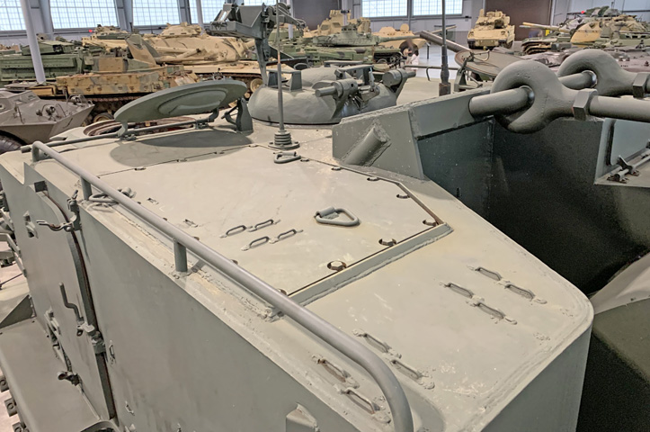
Looking at the cab roof from the left rear, the hydraulic valve panel cover is in the foreground. The driver's hatch cover could be fitted with an infrared periscope M19 for operation in low light conditions. The crane boom topping rods are secured through the rear of the cab.
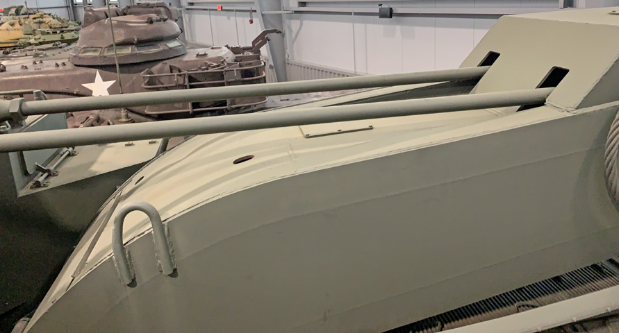
The topping rods are seen here entering the crane.
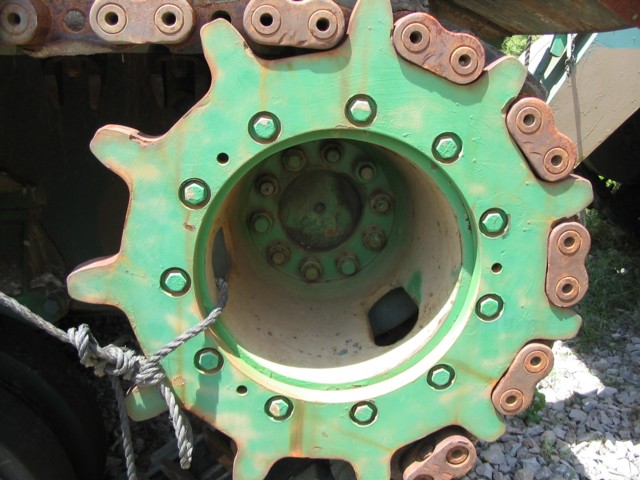
The T107 track, with its longer pitch, required a new sprocket hub for the M51 and M103A2 tank. The older sprocket design was similar in appearance to that on the M48 tank.
