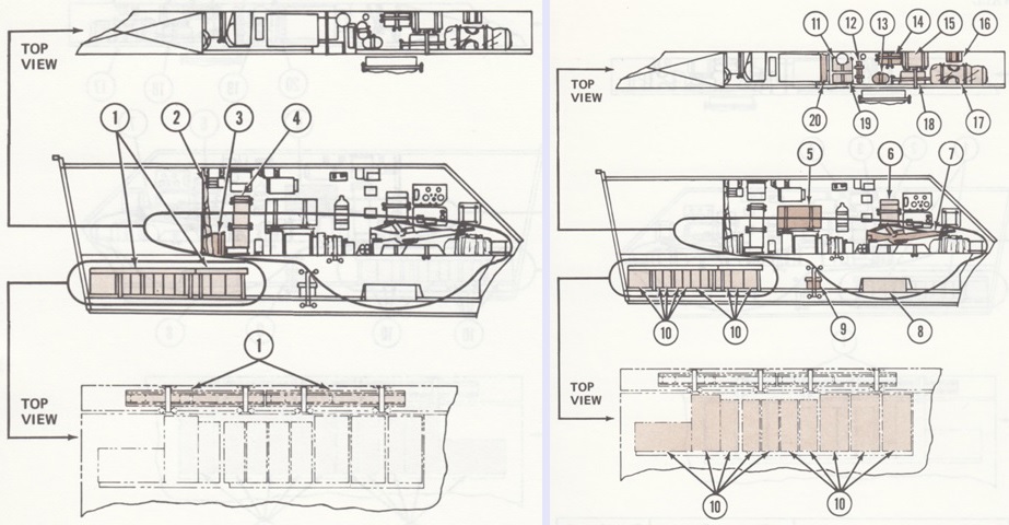
Improved TOW Vehicle M901.
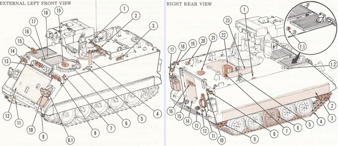
External features of a vehicle based on the M113A2 are labeled in these drawings. A second M26 periscope is unlabeled at the right rear corner of the hull roof. The legend for the left image is: 1. Turret. 2. M60 machinegun. 3. M26 periscope. 4. Squad leader's periscope. 5. External fixed fire extinguisher control handle. 6. Driver's hatch. 7. Front lifting eyes. 8. Left headlight cluster. 8.1. Brush guard. 9. Smoke grenade box. 10. Smoke grenade discharger. 11. Towing hooks. 12. Trim vane. 13. Spare track shoe. 14. Right headlight cluster. 15. Exhaust pipe and exhaust pipe protector. 16. Exhaust grille. 17. Air intake grille. 18. Engine coolant cover. 19. M19 periscope.
The legend for the right image is: 1. Tiedown hook. 1.1. Personnel heater air inlet. 1.2. Personnel heater exhaust. 2. Drive sprocket. 3. Track shroud. 4. Track. 5. Radio antenna. 6. Road wheels. 7. Cargo hatch support. 8. Right taillight assembly. 9. Idler wheel. 10. Telepost. 11. Tow cable. 12. Trailer electrical connector. 13. Towing pintle. 14. Ramp door. 15. Ramp. 16. Rear door vision block. 17. Water can. 18. Left taillight assembly. 19. Rear lifting eye. 20. Fuel flap cover. 21. Vent cover. 22. Cargo hatch. 23. Side armor. (Picture from TM 9-2350-259-10 C4.)
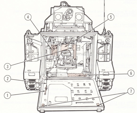
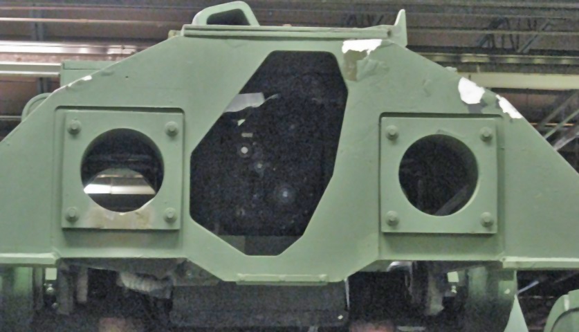
The rear of the vehicle is shown with the turret stowed. 1. Ramp door locking handle. 2. Ramp cable. 3. Lower part of turret. 4. Driver's compartment. 5. Engine compartment rear access panel. 6. Ramp cylinder access cover. 7. Ramp lock. (Picture from TM 9-2350-259-10 C4.)
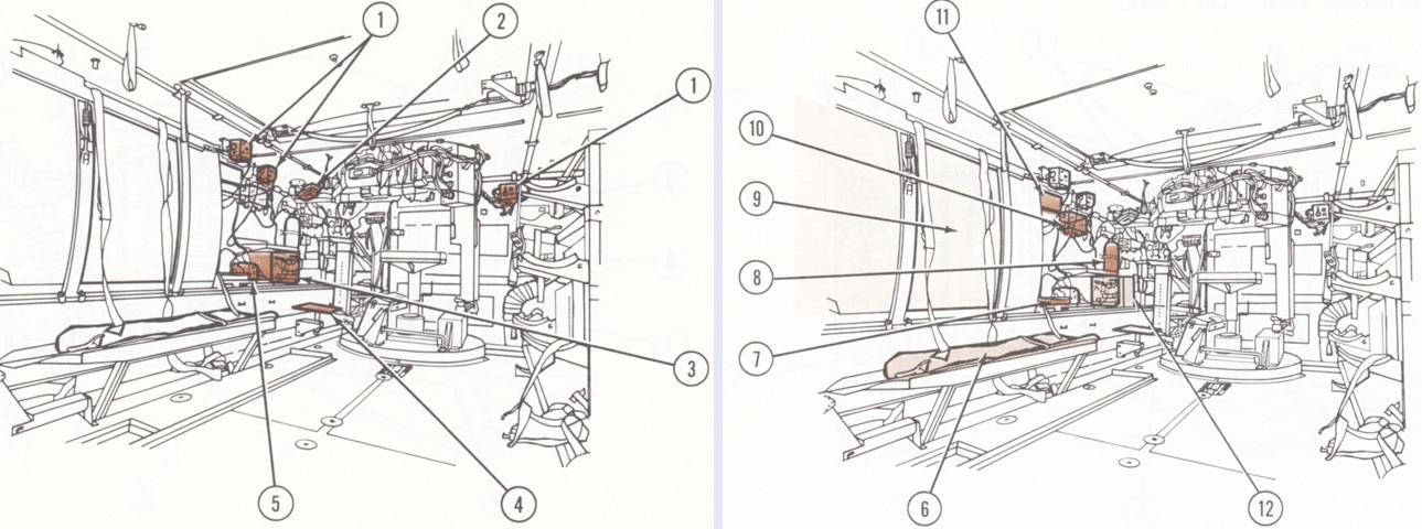
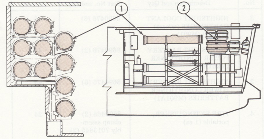
These drawings are looking forward into the interior from the right rear. 1. Intercom control (C-2298/VRC). 2. Front domelight. 3. Radio set AN/VRC-64 or AN/GRC-160. 4. Squad leader's seat. 5. Electrical transient suppressor MX-7778/GRC. 6. Troop seat. 7. Traversing unit mount. 8. Fixed fire extinguisher. 9. Fuel tank. 10. Intercom amplifier AM-1780/VRC. 11. M26 periscope. 12. Spare missile guidance set battery. (Picture from TM 9-2350-259-10 C4.)
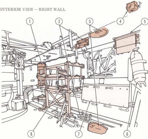
The opposite side of the interior is illustrated in this drawing. 1. Personnel heater. 2. Launch tube stow bracket. 3. Tripod stow bracket. 4. Loader's intercom control (C-2298/VRC). 5. M26 periscope. 6. Portable fire extinguisher. 7. Vehicle battery box. 8. Missile rack. (Picture from TM 9-2350-259-10 C4.)
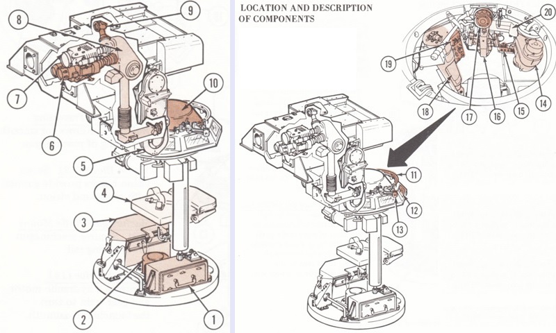
The missile turret is isolated in these images. The nightsight shown is for the M901; M901A1 used the AN/TAS-4A that also performed missile tracking 1. Weapons station emergency power battery. 2. Slipring assembly. 3. Missile guidance set [MGS]. 4. Gunner's seat. 5. Erection arm. 6. Daysight/tracker. 7. Nightsight. 8. Image transfer assembly. 9. 3x telescope. 10. Gunner's hatch cover. 11. Machinegun traversing rail. 12. Vision block. 13. Machinegun pintle mount. 14. Azimuth drive. 15. Nightsight controls. 16. Hand controls. 17. Eyepiece. 18. Hydraulic accumulator. 19. Gunner's control panel. 20. Hydraulic supply pump and motor. (Picture from TM 9-2350-259-10 C4.)
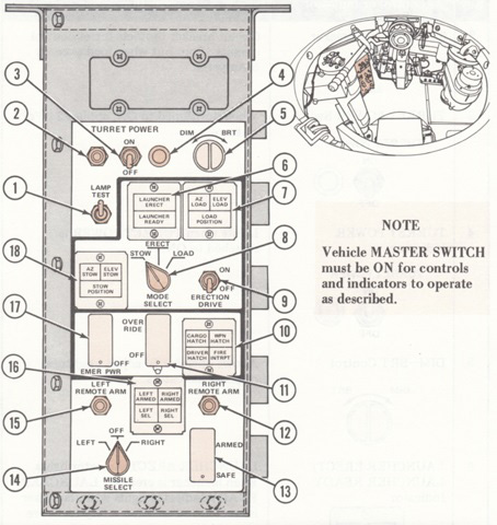
The gunner's control panel is shown here. 1. LAMP TEST switch. 2. 5 amp circuit breaker. 3. TURRET POWER switch. 4. TURRET POWER indicator. 5. DIM-BRT control [for adjusting brightness of panel indicators]. 6. LAUNCHER ERECT/LAUNCHER READY indicator. 7. AZ LOAD/ELEV LOAD/LOAD POSITION indicator [lit when launcher was in the proper azimuth and elevation for loading, and when the launcher then was put in the load position]. 8. MODE SELECT switch [to choose stow, erect, or load modes]. 9. ERECTION DRIVE switch [turned on to place launcher in selected mode]. 10. Interrupt indicator [indicated when cargo, gunner's, driver's or loader's hatches were unsecured or when the launcher was aimed over one of these open hatches]. 11. OVERRIDE switch [overrode fire interruptions and allowed gunner to arm one missile even if the other was not safe. Safety-wired to the off position.]. 12. RIGHT REMOTE ARM (2.5 amp) circuit breaker. 13. SAFE/ARMED switch. 14. MISSILE SELECT switch. 15. LEFT REMOTE ARM (2.5 amp) circuit breaker. 16. LEFT SEL/RIGHT SEL and LEFT ARMED/RIGHT ARMED indicators. 17. EMER PWR (emergency power) switch. 18. AZ STOW/ELEV STOW/STOW POSITION indicator [lit when the launcher was in the proper azimuth and elevation for stowing, and when the launcher was then put in the stow position]. (Picture from TM 9-2350-259-10 C4.)
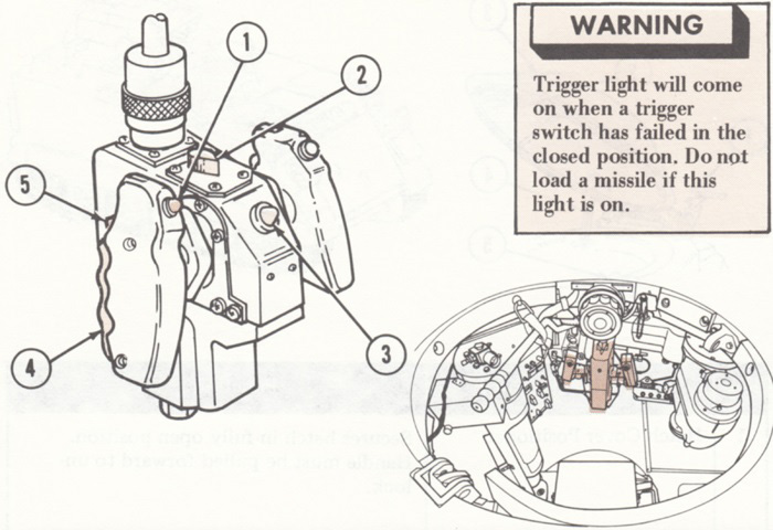
The gunner's hand control assembly is detailed in this sketch. The long handle to his upper left in the inset image is the hydraulic hand pump used to charge the turret hydraulic system in the event of power failure, and the box just under the end of this handle is the fire interrupt alarm box. The gunner's 3x telescope had a 25° field of view; the daylight channel of the daysight/tracker was 13x with a 5.5° field of view, and the nightsight was either 4x with a 6.8° horizontal and 3.4° vertical field of view or 12x with a 2.2° horizontal and 1.1° field of view. 1. Missile firing trigger. 2. Sight select switch [for choosing 3x telescope, daysight/tracker, or nightsight]. 3. TRIGGER light [lit when trigger(s) were depressed]. 4. Handgrip actuator switch [turned handgrip controller on when squeezed]. 5. Slew switch [increased traversing rate 4 times]. (Picture from TM 9-2350-259-10 C4.)
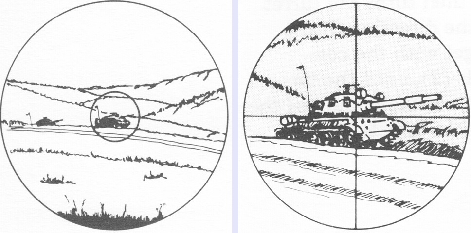
The gunner's 3x daylight wide field of view telescope had a circular reticle used to acquire targets, as sketched on the left. When the target was centered in the circle, the gunner switched views to the daysight/tracker as depicted on the right, and kept the crosshairs on the target throughout the missile flight until impact. (Picture from TM 9-2350-259-10 C4.)
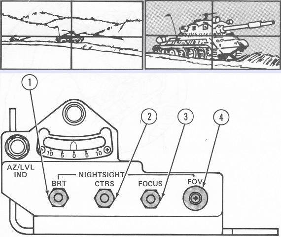
As seen at the bottom of the image, the gunner's 3x nightsight controls were under a level that indicated sideslope of up to 10°; if a missile was fired with the turret tilted above 10°, the hit probability was lowered. The upper left drawing depicts a target seen through the nightsight channel wide field of view. At the upper right, the target is drawn as seen through the narrow field of view of the nightsight. 1. Brightness control. 2. Contrast control. 3. Focus control. 4. Field of view selector. (Picture from TM 9-2350-259-10 C4.)
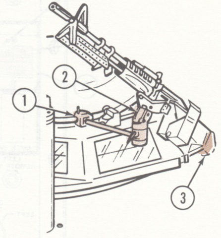
To place the machine gun into its travel lock, the pintle mount frame (1) was swiveled to the left of the turret and the gun's buttstock was inserted into the travel lock receiver (3). The spring-loaded travel lock (2) would then snap into place. The machine gun was to be stowed when the turret was being operated. (Picture from TM 9-2350-259-10 C4.)
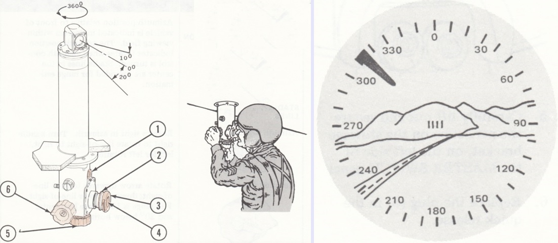
The squad leader had a 4x periscope with a 12.5° field of view that could be elevated 10° and depressed 20°. The periscope rose 22" (56cm) above the deck to the top of the assembly, and 20" (51cm) above the deck to the line-of-sight. 1. Humidity indicator [turned pink when desiccant needed replaced]. 2. Focus control. 3. Eye cup. 4. Reticle. 5. Azimuth control. 6. Elevation control.
As illustrated on the right, the squad leader's periscope had a position indicator arrow that rotated around the exterior of the reticle and showed the periscope's viewing angle relative to the front of the vehicle, measured in degrees. Four stadia lines were centered to help with range estimation; the center lines were 3 mils apart, while the distance between the outer lines was 8 mils. (Picture from TM 9-2350-259-10 C4.)
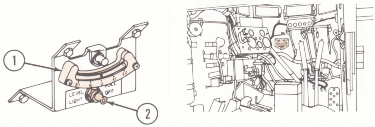
The driver's compartment was similar to the base carrier besides the addition of a level that indicated sideslope of up to 20°. 1. Degree scale and dial. 2. Light switch. (Picture from TM 9-2350-259-10 C4.)
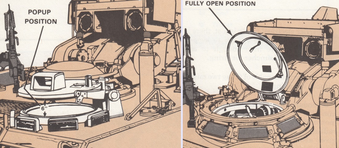
The driver's and gunner's hatches are illustrated on the left and right, respectively. The driver's hatch could be opened fully vertically, and also had a pop-up position that raised the hatch 6" (15cm) above the hatch opening. Similarly, the gunner's hatch could be opened fully as illustrated, or locked in a pop-up position that provided similar vision as the driver's pop-up hatch position. (Picture from FM 23-34-1 Improved TOW Vehicle, M901.)
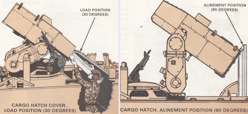
The cargo hatch cover could be opened to three positions. The loading position provided the loader with overhead protection while reloading the launcher, and the alinement position locked the hatch at 90°. The launcher could be lowered with the hatch in this position for alinement servicing of the daysight/tracker or servicing of the nightsight. The third position was fully open. (Picture from FM 23-34-1 Improved TOW Vehicle, M901.)
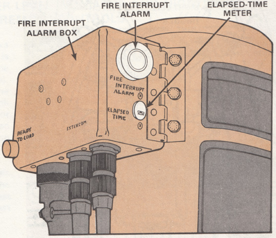
The fire interrupt alarm box warned the crew if a missile was selected when the launcher was in a fire interrupt zone or a hatch was open. The elapsed-time meter tracked how long the turret had been operated. On the side of the box was the ready-to-load light, which illuminated when the launcher was in the correct load position. The two connections at the bottom of the box closest to the elapsed-time meter were for the gunner's intercom. (Picture from FM 23-34-1 Improved TOW Vehicle, M901.)
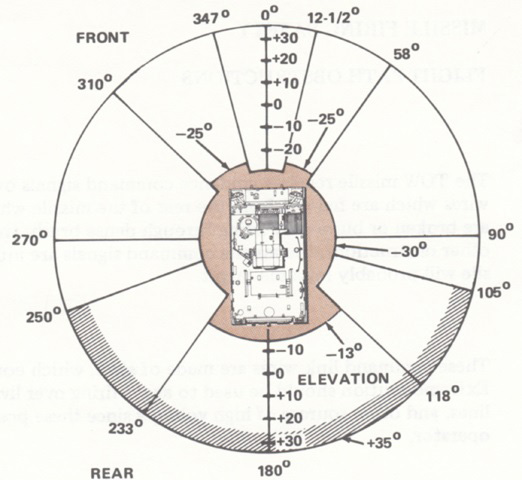
Missiles could be fired at any azimuth with the launcher at -13° to +35°. In order to keep the missiles from impacting the vehicle, however, three no-fire zones were created: from 12.5° to 58° azimuth and from 310° to 347.5° azimuth, both with the launcher below -25°; and from 118° to 233° azimuth with the launcher below -13°. If the launcher was aimed in any of these zones, the FIRE INTRPT light would illuminate and a buzzer sounded. These no-fire zones could be overridden by the gunner in an emergency. Additionally, firing a missile above +24° elevation from 250-105° azimuth could cause missile exhaust to enter the engine and as well the crew compartment via the engine access panels. (Picture from TM 9-2350-259-10 C4.)
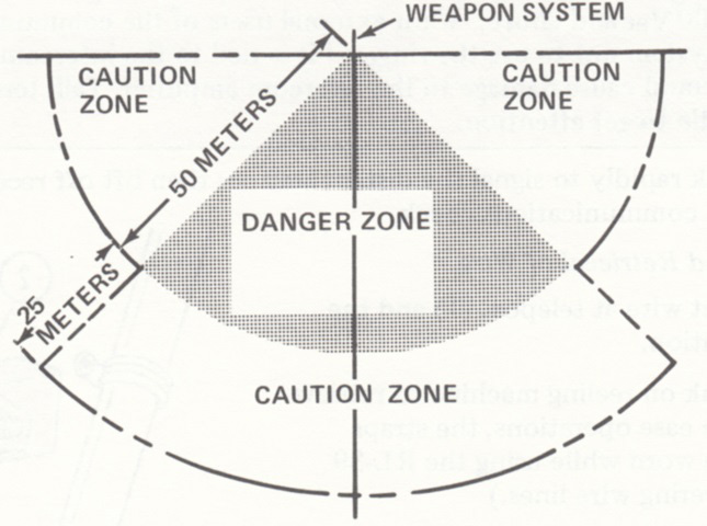
A danger zone 50m (160') long and 45° right and left from the launcher was formed during missile launch. Backblast and flying debris could both cause injury, and personnel would only be permitted in that area in an emergency. Personnel in the caution zones diagrammed would suffer little injury if wearing hearing protection and facing away from the launcher, but presence in the caution zones was again restricted to absolute necessity and if personnel were aware of the risks. (Picture from TM 9-2350-259-10 C4.)
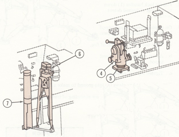
A ground launcher was stowed on the vehicle as well. The traversing unit (4) was held to the left interior wall by a coupling clamp (5), while the tripod (6) and launch tube (7) were stowed at the right rear of the passenger compartment. The vehicle's nightsight, daysight/tracker, and MGS were dismounted and assembled to the ground mount. (Picture from TM 9-2350-259-10 C4.)
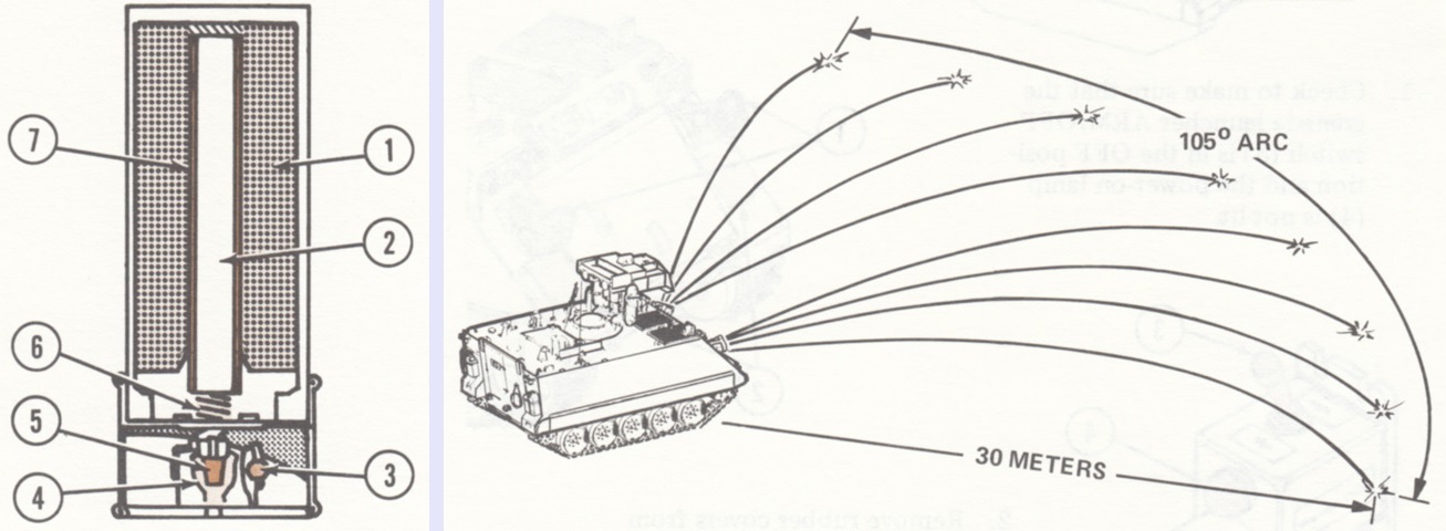
A cross-section of the British-designed L8A1 screening smoke grenades used with the M243 grenade launcher is drawn on the left, and the firing pattern of the smoke grenade launchers is on the right. The grenades were 2.61" (66mm) in diameter, 7.28" (18.5cm) long, and weighed about 1.5lb (.68kg). 1. Red phosphorous/butyl rubber mix. 2. Gunpowder bursting charge. 3. Fuze. 4. Firing contact. 5. Propellant charge. 6. Delay composition in delay holder. 7. Rubber case. (Picture from TM 9-2350-259-10 C4.)
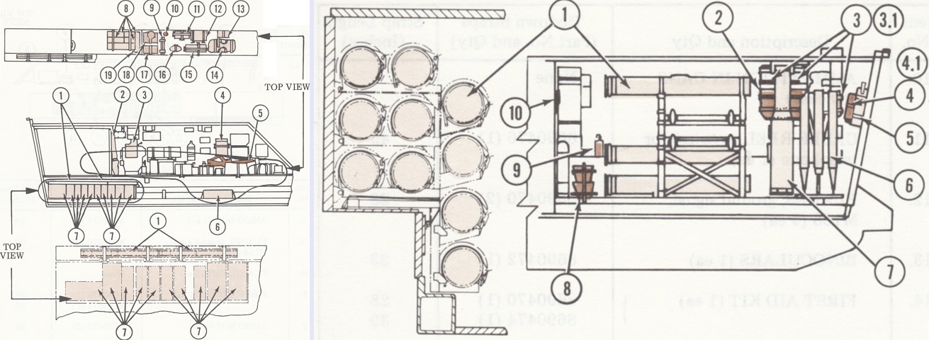
Different stowage plans were drawn up for vehicles use by Mechanized Infantry and Armored Cavalry units. Above at the left is stowage along the left wall of a Mechanized Infantry vehicle. 1. LAW missile [sic] (3 ea). 2. Spare barrel and cleaning equipment for M60 machinegun. 3. TOW traversing unit. 4. IR periscope. 5. M16 rifle (2 ea). 6. Field rations (1 case). 7. Ammo cans (10 cases). 8. Ammo box (4 ea). 9. Flares, ground signal, M158 (4 ea). 10. Flashlight. 11. First aid kit. 12. Ammo box. 13. Field stove. 14. Tool bag. 15. Telephone set. 16. Binoculars. 17. Ammo box. 18. Cable reel (w/wire) for telephone. 19. Spare MGS battery.
The right side is sketched on the right. 1. Encased missile (10 ea). 2. Nightsight collimator (w/case). 3. Nightsight coolant cartridges (w/case) (3 cases) (M901). 3.1. Nightsight battery power conditioner (M901A1). 4. Nightsight batteries (w/case) (M901). 4.1. Nightsight battery power conditioner batteries (M901A1). 5. Fire extinguisher, portable. 6. Tripod, M159E1. 7. Launch tube, M21. 8. Night vision goggles (w/case) (2 cases). 9. M17 periscope. 10. Pamphlet bag. (Picture from TM 9-2350-259-10 C4.)
Stowage along the left wall of an Armored Cavalry vehicle is detailed here. 1. LAW missile [sic] (3 ea). 2. Spare barrel and cleaning equipment for M60 machinegun. 3. Night goggles (w/case). 4. Field rations (1 case). 5. Nightsight. 6. IR periscope. 7. M16 rifle (2 ea). 8. Field rations (1 case). 9. Night goggles (w/case). 10. Ammunition in cans (10 cans). 11. Cable reel (w/wire) for telephone. 12. Flares, ground signal, M158 (4 ea). 13. Binoculars. 14. First aid kit. 15.Ammo box. 16. Field stove. 17. Tool bag. 18. Telephone set. 19. Ammo box. 20. Spare MGS battery. (Picture from TM 9-2350-259-10 C4.)
Stowage along the right wall of an Armored Cavalry vehicle is detailed here. 1. Encased missile (10 ea). 2. Nightsight collimator (w/case). (Picture from TM 9-2350-259-10 C4.)
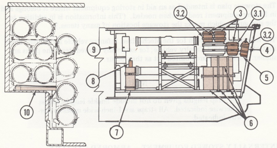
3. Nightsight coolant cartridges (w/case) (3 cases) (M901). 3.1. Nightsight battery power conditioner (M901A1). 3.2. Nightsight battery power conditioner batteries (M901A1). 4. Fire extinguisher, portable. 5. Nightsight batteries (w/case) (M901). 6. 7.62mm ammunition (w/case) (4 cases). 7. 7.62mm ammunition (w/case). 8. M17 periscope. 9. Pamphlet bag. 10. Lower tripod stow bracket (when removed from floor). (Picture from TM 9-2350-259-10 C4.)
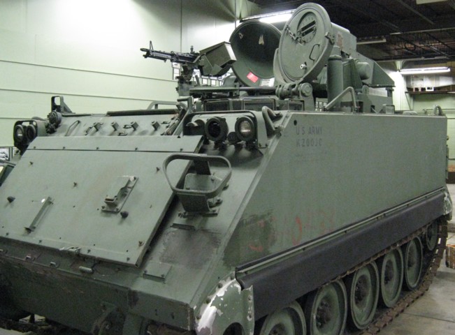
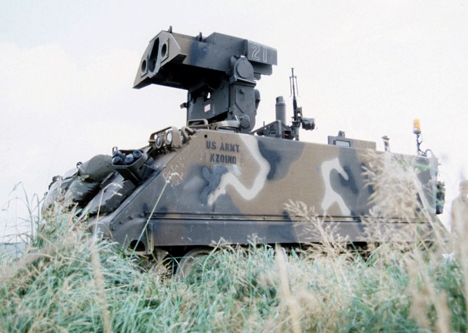
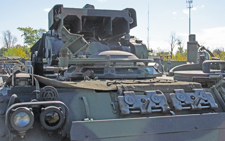
The engine exhaust and raised rear idler indicate that this M901 is based on the M113A2. The TOW targeting head is in the stowed position, aimed to the rear and tilted down. The driver's hatch at the front left corner of the hull and the turret hatch are both open, and the cylindrical structure behind the driver's position is the commander's periscope.
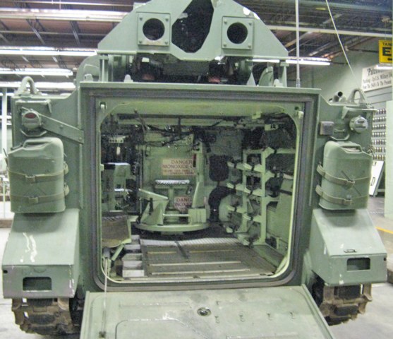
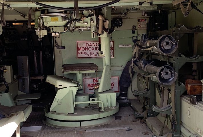
Internal stowage of the vehicle can be seen here. Missile racks line the right wall, and the lower part of the turret can be seen as well. On the turret floor by the missile gunner's left foot would be the weapon station emergency power battery, and the MGS would be on the opposite side of the turret floor. The gunner's seat is visible just below the monoxide warning on the engine compartment rear access panel. The turret slip ring can be seen directly under his seat.
A 2-man bench seat dominates the opposite wall of the passenger compartment.
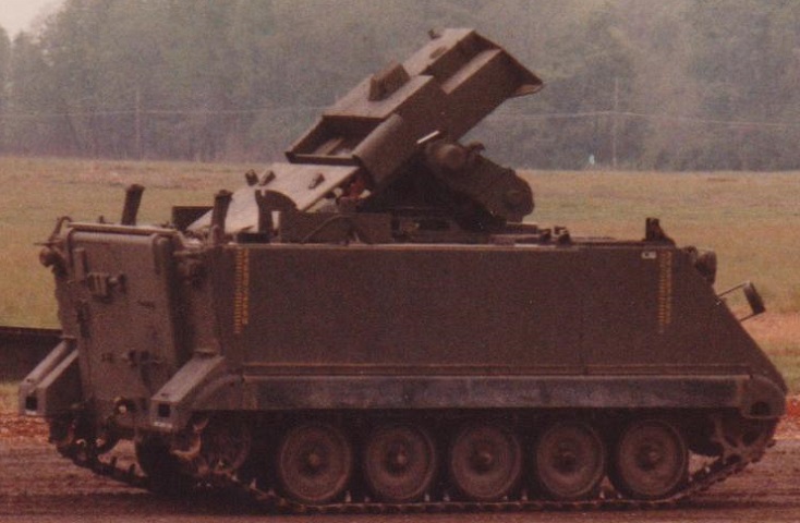
The hammerhead turret on this vehicle is raised and ready to fire. The rest for the missile turret can be seen towards the rear of the vehicle. This ITV was participating in Exercise REFORGER '85, and the yellow strobe light is part of a wargaming system that flashed if the vehicle had been "destroyed." (Picture taken 1 Jan 1985; available from the Defense Visual Information Center.)
The reloading process is illustrated here, with the launching head tilted back so that the missiles could be inserted through the vehicle's cargo hatch. (Photo by Richard S. Eshleman.)
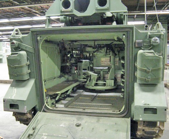
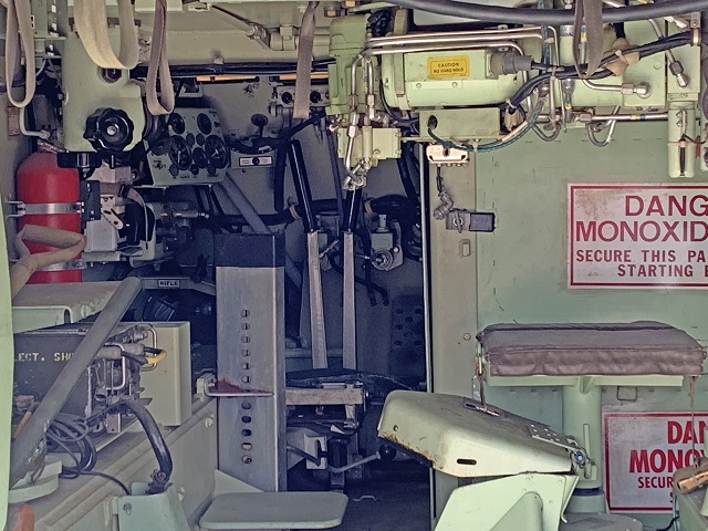
A closer look at the interior is provided here.
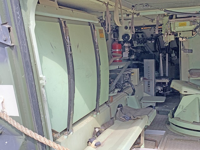
The fuel tank is behind the bench, and to the front communications equipment and a fire extinguisher bottle are visible. The driver remained at the front left of the vehicle.
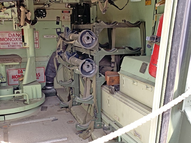
A portable fire extinguisher was stowed to the right of the rear ramp, and stowage for a missile tripod and launch tube was behind the missile racks.
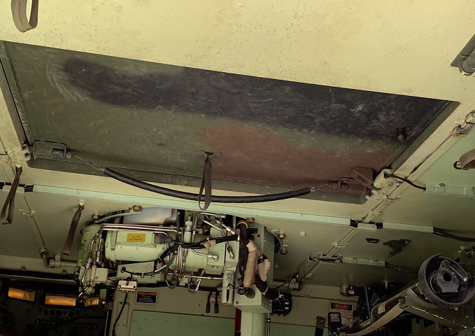
The interior of the roof hatch was painted to match the vehicle exterior so it would not contrast when opened.
The driver's position and steering levers can be seen in this image, and the commander's periscope is visible to the left hanging down from the roof ahead of the handhold loops.
The hole in between the two missile launcher tubes houses the tracking and guidance optics. The daysight/tracker assembly is on the bottom of the opening, and the nightsight is above these.
The rear of the stowed launcher head reveals the mounting channels for the missile tubes. A machine gun mount and ammunition box mount are present at the turret hatch, but the machine gun itself is not.
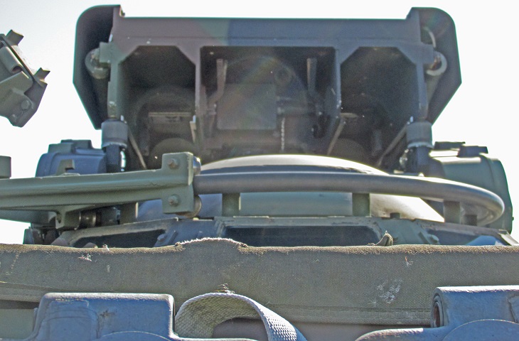
Details of the underside of the rear of the launcher head can be gleaned through the sunspot.
