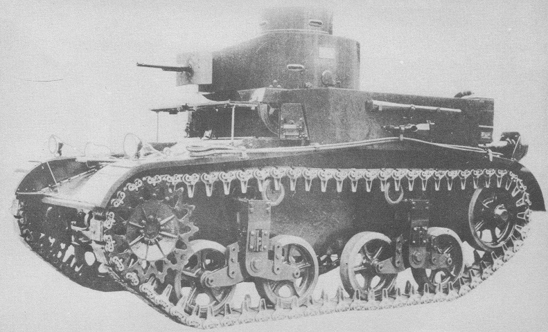
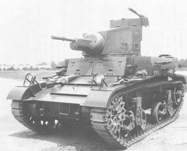
Light Tank M2A1.
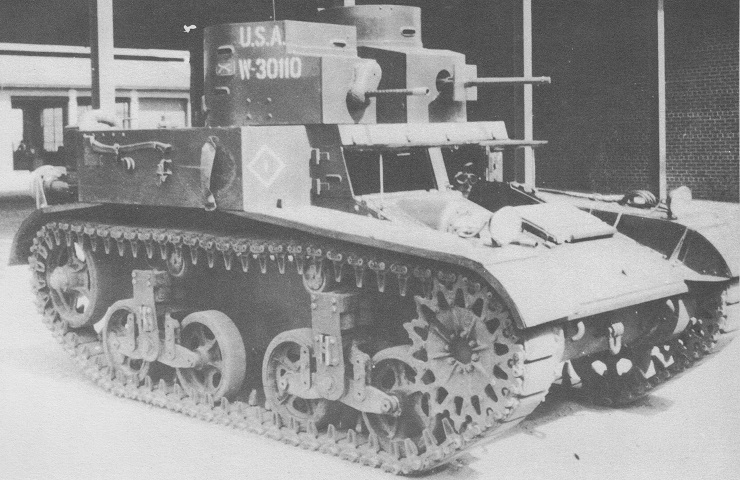
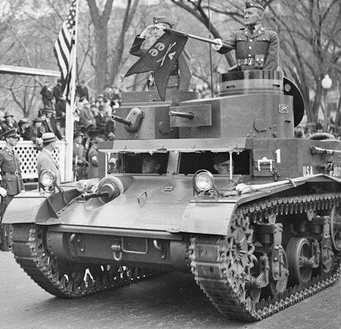
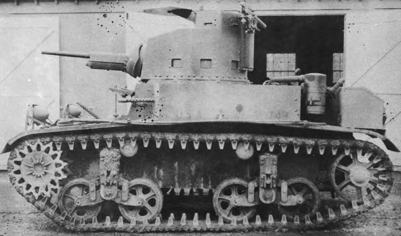
The single cylindrical turret with an extension for weapons mounts marks this vehicle as a light tank M2A1. Otherwise it is very similar to the combat car M1. The light tank also featured a cylindrical cupola on the turret rear. The drivers' hatches are open in this view, and a disassembled mattock is stowed on the vehicle's left side, above the tow cables. The US Army was not afraid of chrome on tactical vehicles in the 1930s, and this tank's headlights and siren would all sparkle in the sun. (Picture from Development of Armored Vehicles, volume 1: Tanks.)
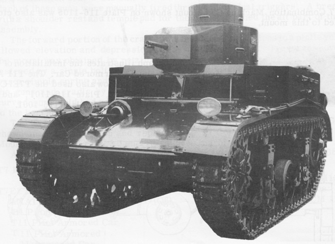
The glossy, reflective paint on this machine is notable. The assistant driver's door and the driver's upper door are both open. The driver had another door in the hull upper front plate, but the bow machine gun precluded such a concession for the assistant driver. Vision slits are apparent in the commander's cupola and the turret side. The spatial relationship of the turret machine guns can also be gleaned from this angle. (Picture from Weapon Mounts for Secondary Armament.)
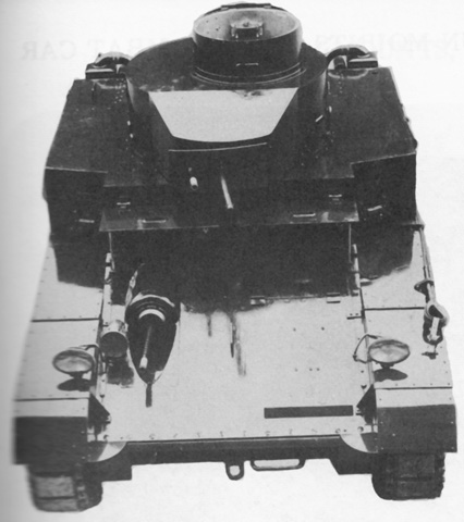
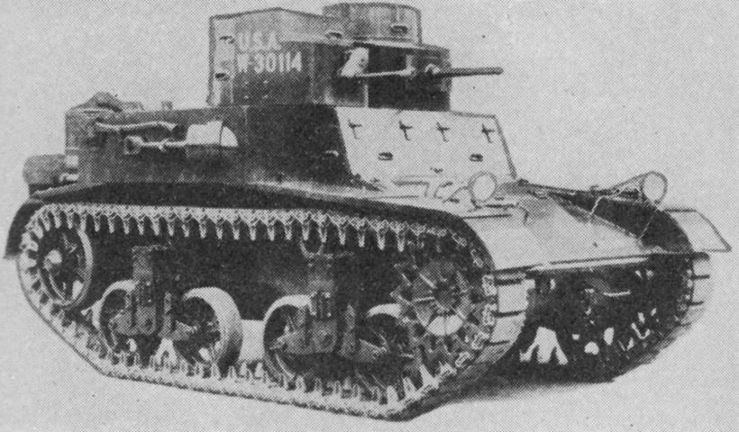
The commander's cupola door was hinged to the rear, and the shape of the turret's forward projection with the armament mount can be seen from above. The coaxially-mounted machine guns were provided with an armored shield. The air cleaners at the hull's rear corner are square in cross-section. (Picture from Weapon Mounts for Secondary Armament.)
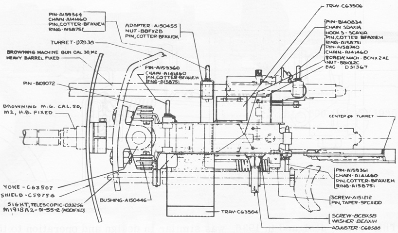
The combination machine gun mount M7 is sketched from above. A telescopic sight M1918A2 was mounted to the left of the .50cal machine gun. The front of the gun cradle was attached by trunnions to a pintle yoke that allowed elevation. To traverse the guns in the mount, the yoke was rotated in a pintle socket attached to the turret wall. The equilibrator spring is visible between the telescope and the .50cal. (Picture from Weapon Mounts for Secondary Armament.)
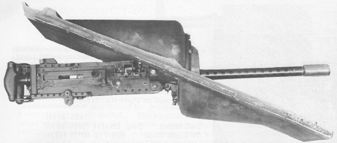
The assistant driver's machine gun was housed in the 6.5" (16.5cm) ball mount M8. No aiming device was provided; correction was achieved by using tracers or impacts. A 35° cone of fire was possible. The later ball mount M10 was similar except that a .30cal M1919A4 machine gun was used. (Picture from Weapon Mounts for Secondary Armament.)
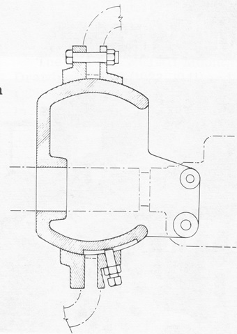
A cross-section of the bow machine gun ball mount M8 is sketched here. The .30cal M2HB was attached to the cradle by its front mounting holes, and no counterbalance weight or equilibrator spring was fitted. (Picture from Weapon Mounts for Secondary Armament.)
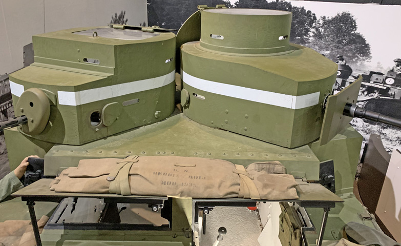
This vehicle, serial number 11, was the first M2A2 light tank to be manufactured. The striking twin turret layout provided the ability to engage threats from multiple directions. The commander's cupola is visible on the larger left turret. The drivers' doors are open on this vehicle as well, and it is apparent that the driver would have an easier time egressing under duress than the assistant driver, since the bow machine gun mount precluded adding a door in the hull front plate for him. An axe is stowed on the tank's right side, and a shovel would normally be stowed below it, however the strap for the shovel blade appears damaged on this tank. (Picture from Development of Armored Vehicles, volume 1: Tanks.)
The driver's doors are closed, revealing the peepholes used for protected vision. The shovel is present under the axe. (Picture from FM 30-40 Military Intelligence Identification of United States Armored Vehicles.)
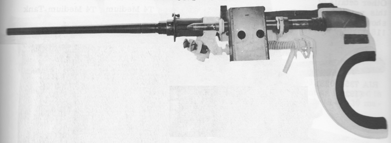
The caliber .50 turret mount M9 can be seen here with the machine gun and M1919A2 telescope mounted. The front of the gun cradle was secured in a pintle yoke by trunnions that provided elevation for the gun, while traverse was accomplished by moving the yoke in a pintle socket bolted to the turret front. The shoulder rest used to assist aiming is obvious at the rear. (Picture from Weapon Mounts for Secondary Armament.)
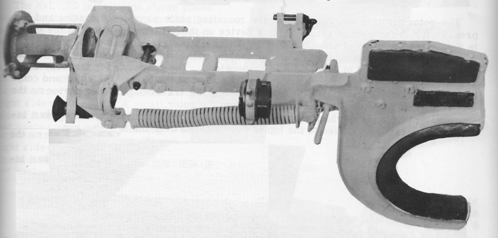
The M9 mount cradle is shown without the machine gun or telescope. (Picture from Weapon Mounts for Secondary Armament.)
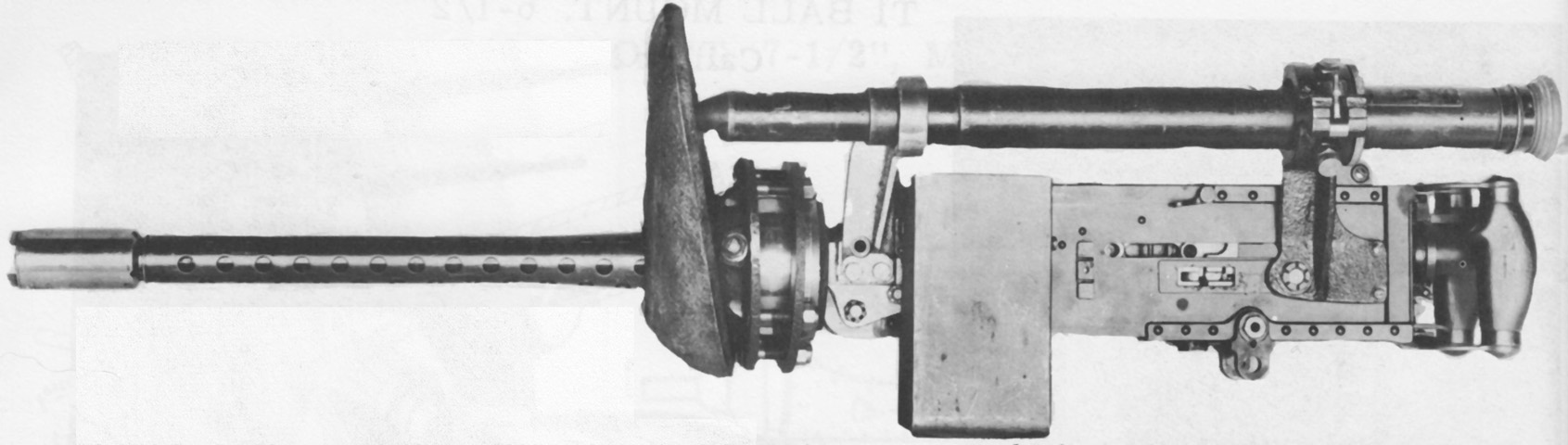
The 3.5" (8.9cm) ball mount T2 from the right turret is shown fitted with its .30cal M2HB machine gun, sighting telescope, and armor shield. In this mount, the split spherical housing was made up of a flange on each side of the structure to which it was bolted, and the joint between the flanges can be seen. The mounting bracket for the telescope attached to the gun cradle at the front and the gun body at the rear. The mount allowed a cone of fire of ~34°. The later ball mount M14 was essentially similar, and the ball mount M12 allowed the use of a full-width telescope headrest and the .30cal machine gun M1919A4 instead of the .30cal M2HB. (Picture from Weapon Mounts for Secondary Armament.)
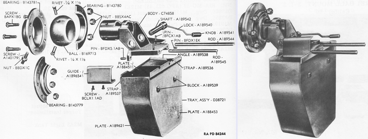
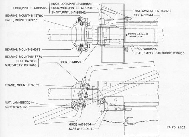
A late 3.5" (8.9cm) ball mount M13 is shown in an exploded view on the left and assembled on the right. An ammunition tray was below the gun, and two rods extended to the rear for hanging a bag to catch expended cases. On earlier M13s, the ball C64522 was used, which lacked supports for the ammunition tray and expended casing bag rods. (Picture from Weapon Mounts for Secondary Armament.)
Cross-sections of the assistant driver's ball mount M13 are drawn here. (Picture from Weapon Mounts for Secondary Armament.)
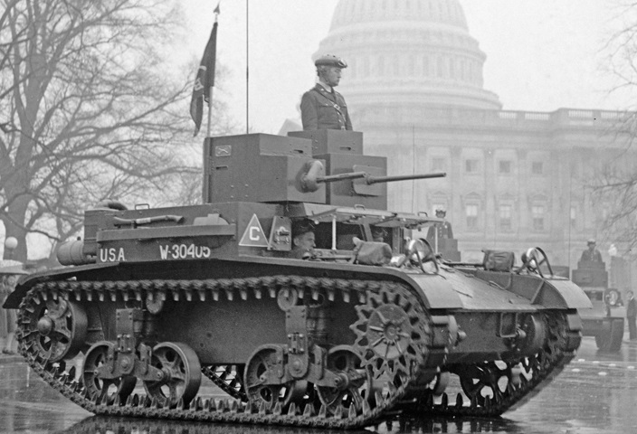
All four members of the crew can be seen in this tank taking part in the Army Day parade. The hatch door for the right turret rested on the rear portion of the roof, but the commander's cupola hatch was hinged so that it rested against the turret rear. This vehicle has the earlier rounded turrets and still no guard over the tool stowage on the sponsons. (Picture taken 6 Apr 1938 by Harris & Ewing, Inc.; available from the Library of Congress.)
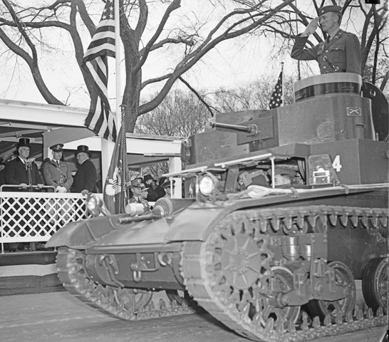
The cramped confines of the light tank are illustrated from this angle, as the right turret gunner's waist can be seen just beyond the driver's head. President Franklin D. Roosevelt is in the reviewing stand; to his left are Brigadier General Albert Cox and Assistant Secretary of War Louis Johnson. (Picture taken 6 Apr 1938 by Harris & Ewing, Inc.; available from the Library of Congress.)
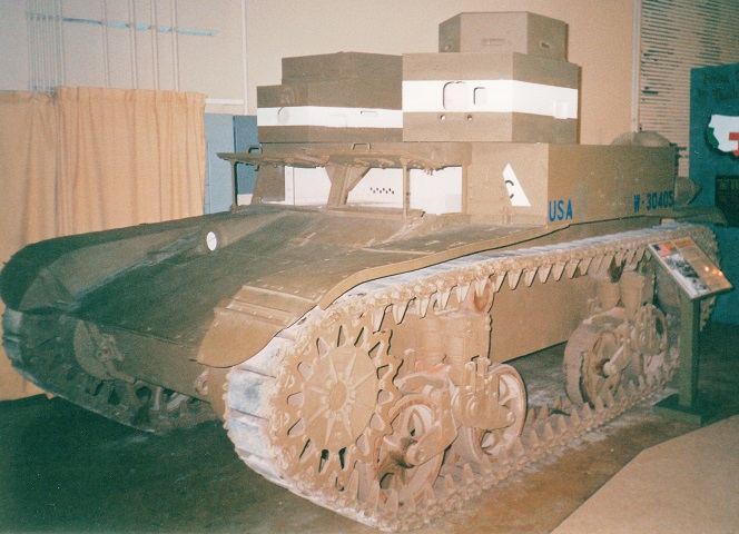
This vehicle is topped by round turrets, and the drivers' hatches are open. Pistol ports are open on both turrets, and a submachine gun is emerging through the commander's pistol port.
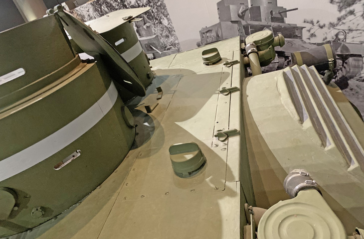
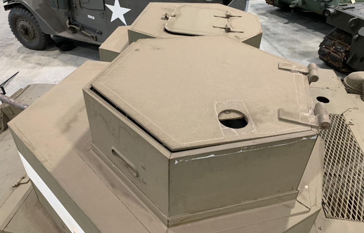
An overhead angle highlights the open turret hatches. The commander's rested against the rear of the turret while the .30cal turret hatch rested nearly horizontally on the turret roof.
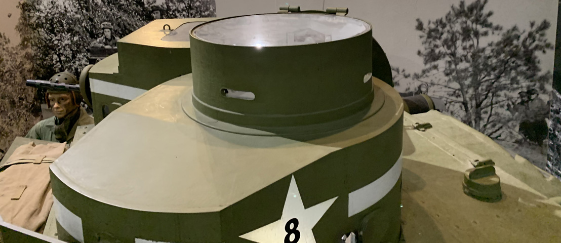
The interior of the commander's cupola can be glimpsed, and the shutter for the rear vision slit can be seen on the far side of the cupola.
A closer view is provided of the side of the commander's turret. The cupola hatch is open and resting against the turret rear, and a fuel filler cover is visible on the rear deck.
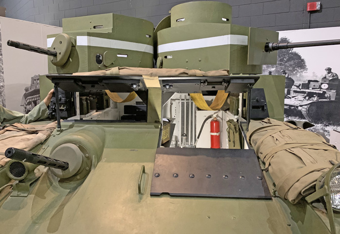
The open drivers' doors provide a glimpse into the vehicle's interior. Strap seats are slung across the turret interiors, an oil cooler is mounted on the engine compartment bulkhead, and the knob of the transmission gearshift lever is visible at the driver's right side.
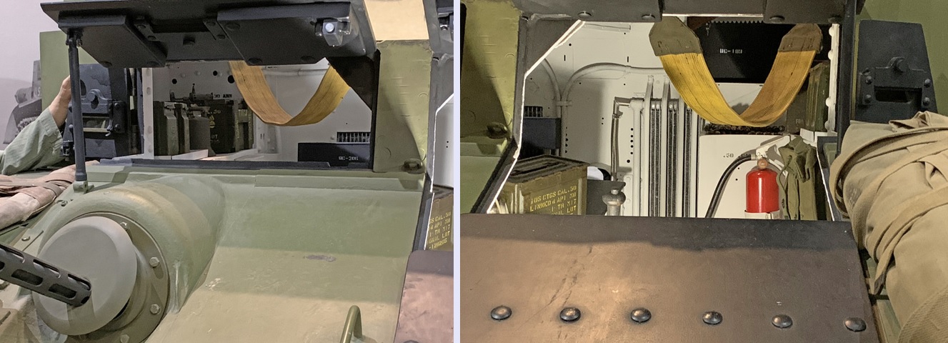
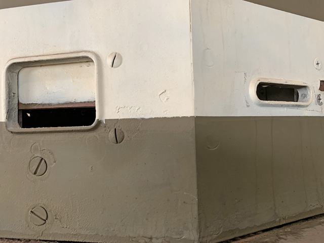
Closer views through the assistant driver's and driver's doors are at the left and right, respectively. The bow machine gun precluded a lower door for the assistant driver.
The drivers also had a hinged armor flap outboard of their doors. Shutters can be seen in the driver's side flap as well as the main doors.
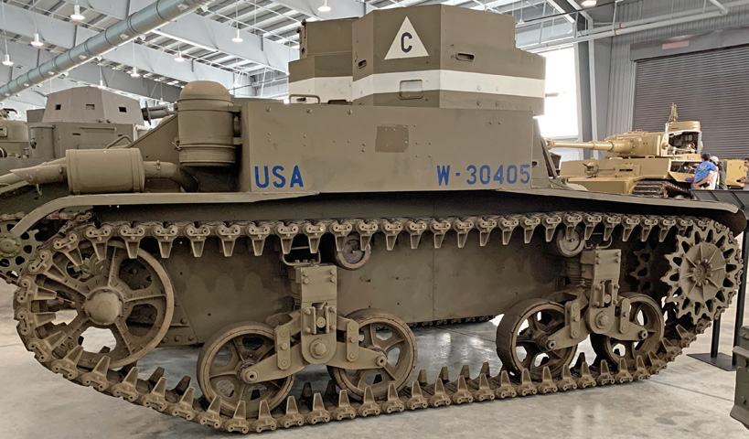
The volute springs behind the suspension brackets are visible from the front, and the tops of the bogies featured track skids. Note the distance between the two bogies.
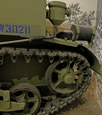
The rear fenders over the idler wheel were relatively short, and the wheel itself was mounted farther forward than on the M2A3 or M2A4. The engine exhaust muffler was supported almost at the very end of the fender.
Fuel fillers and access panels for the engine were immediately aft of the turrets. A mesh screen would typically be found between the fuel filler covers instead of the solid panel seen here.
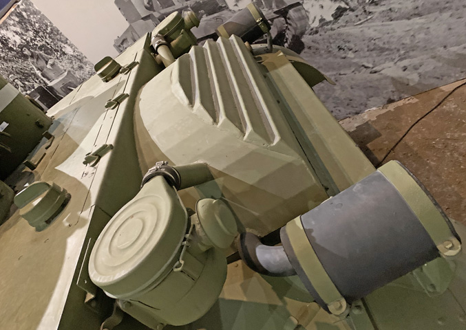
The engine air cleaners mounted on this machine are unusual, and the engine cover has been reproduced for display.
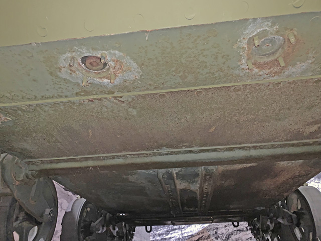
The hull underside featured stiffening braces, and drain plugs are visible near the top of the image, although their covers are absent.
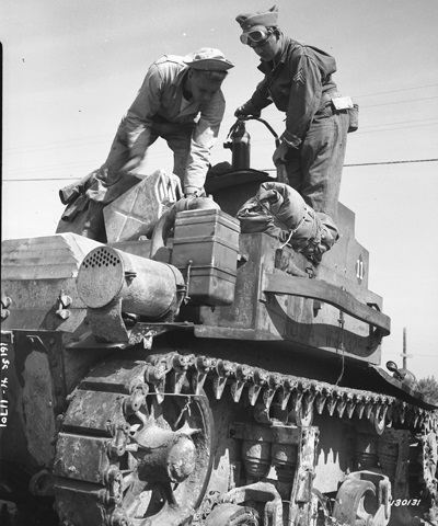
The tank is seen here being refueled; as was standard practice, the sergeant is standing by with a fire extinguisher. The right-side cylindrical engine exhaust is mounted to the rear of the fender, and just behind this is one of the engine's rectangular air cleaners. The turrets and engine covers are the later angular designs. Note that a guard has been welded to the sponson over the tool stowage. (Picture taken 16 Oct 1941 by the 161st Signal Photo Co.; available from the National Archives.)
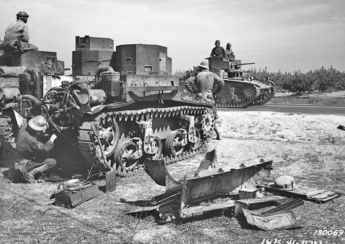
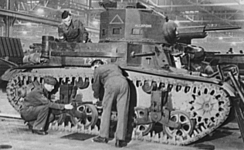
The panels covering the engine have been removed on this tank in order to effect some type of repair. (Picture taken 16 October 1941 by the 161st Signal Photo Co.; available from the National Archives.)
The increased spacing between the suspension bogies and the more rearward position of the idler are obvious when comparing the light tank M2A3 to its predecessors. The rear fenders were extended in turn, while the engine exhaust mufflers retained their original position near the superstructure. (Picture taken 6 Apr 1939 by Harris & Ewing, Inc.; available from the Library of Congress.)
The easiest way to differentiate the M2A3 from the M2A2 is the increased distance between the suspension bogies in the latter tank. The turrets were also slightly spaced farther apart. The M2A3 featured the flat-faced turrets also common to late-model M2A2s.
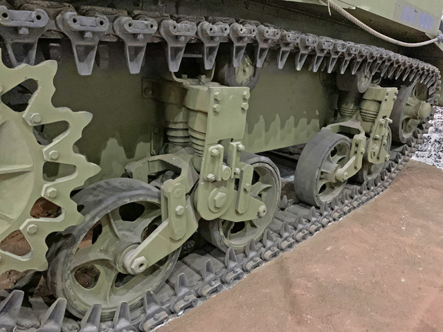
This view makes it easy to compare the space between the suspension bogies on the M2A3 with the M2A2 above. The new suspension arrangement arose from tests that also led to the combat car M1A1. Even though the M2A3 weighed more than the M2A2, its larger ground contact area gave it a lower ground pressure. The idler wheel was also moved farther back, and the rear fenders were extended to provide coverage for the idler wheel's new position.
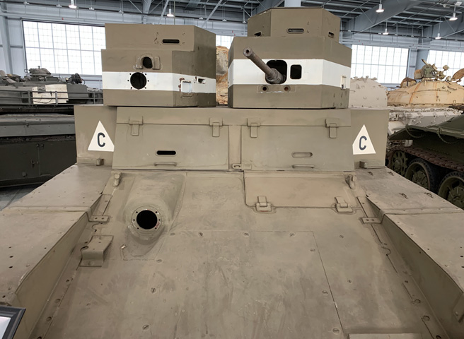
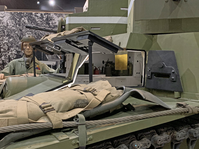
The machine gun mounts, telescopes, and machine gun shields are absent, but the apertures for the machine guns and sighting telescopes can still be seen in the turrets' front plates. The gunner's smaller turret had a vision slit at his front upper left, and the commander's cupola had vision slits to the front, sides, and rear. The spacing between the turrets had been increased from the light tank M2A2. The driver had two outward-opening doors, while the bow machine gun eliminated the assistant driver's potential for a lower door.
A partially-opened pistol port and an open vision slit in the commander's turret are isolated here.
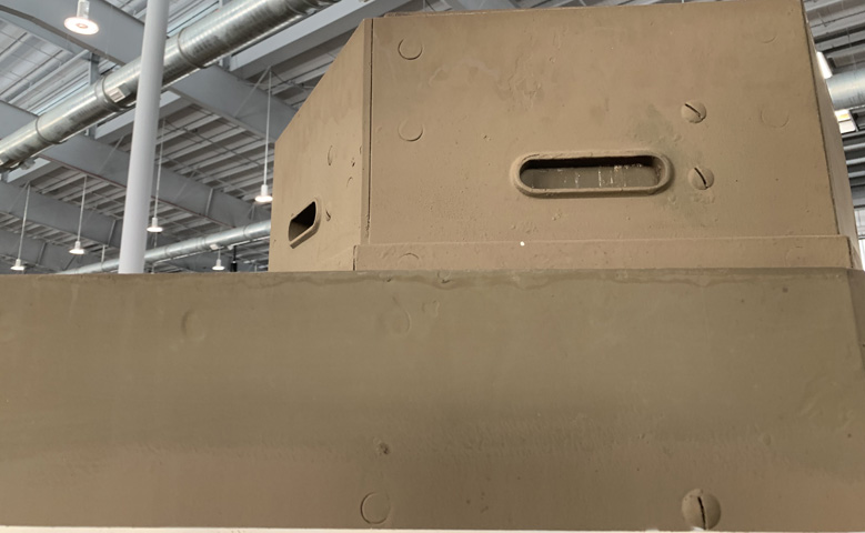
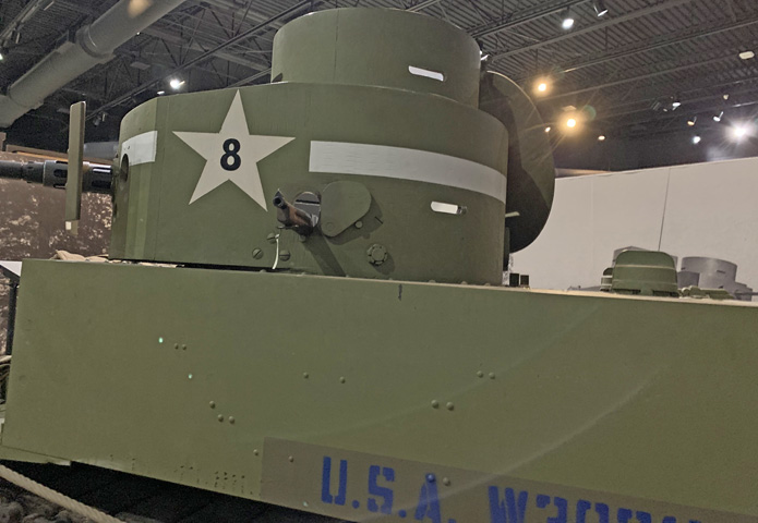
The commander's cupola is seen here from the lower left. The vision slit facing the camera is closed.
The commander's cupola door featured an aperture for signaling. There were vision slits in four of the six faces of the cupola, with the right rear and left rear plates being blank. The cupola was inset a bit from the turret edge, so the door did not lie flat on the cupola rear when it was open.
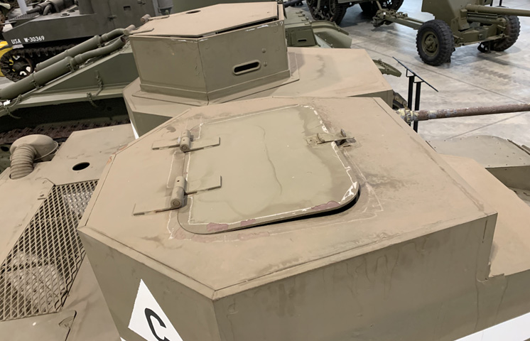
The gunner's turret hatch was also hinged to the rear, and would lie flat on the turret roof when fully open.

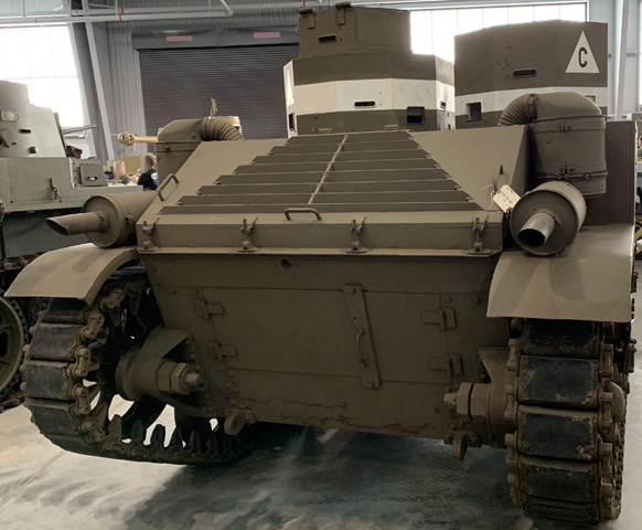
The rear hull on the M2A3 was modified from the M2A2 by the addition of the doors in the lower plate. The previous design had a central access cover and two covers on either side of the rear hull that needed to be removed to service the engine. The characteristic short intake pipes from the air cleaners mark this tank as having a gasoline versus diesel engine.
The rear hull is seen from the opposite angle.
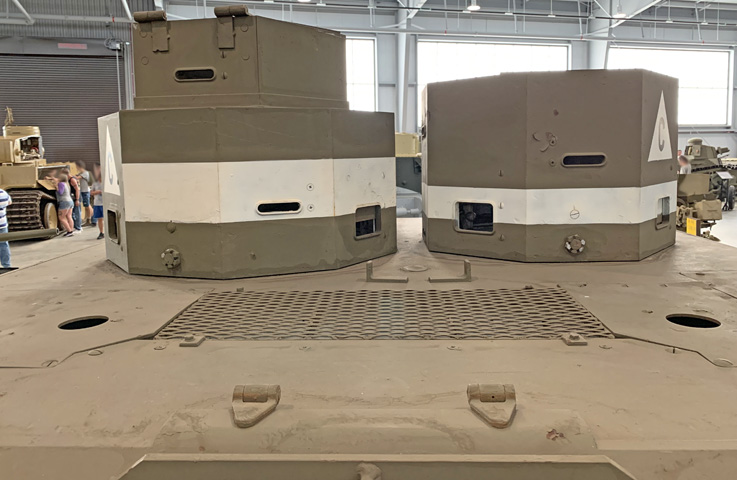
The engine deck and rears of the turrets are highlighted here. An air intake screen was central to the engine deck, with apertures for the fuel tank fillers to each side. The turrets were provided with both vision slits and pistol ports around their circumferences.
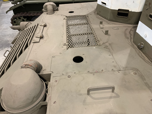
The engine deck is seen from the side. The engine and fuel tanks are not present in this tank.
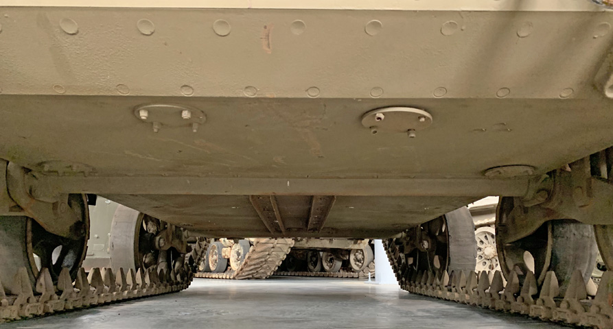
The bottom of the hull is shown from the front of the tank.
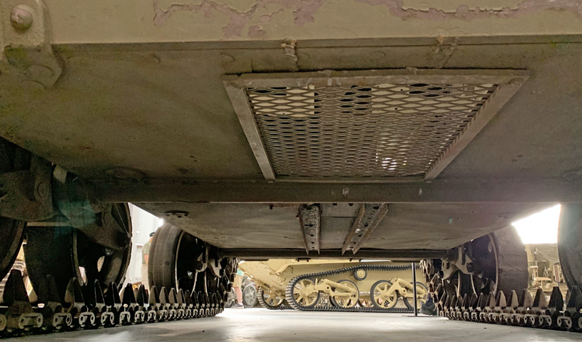
The rear hull bottom is the subject of this image. The mesh screen under the engine compartment is presumably a stand-in for an original solid access panel.
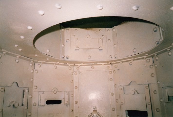
This is a view inside the larger commander's turret. The pistol ports ringing the turret and a vision slot in the turret cupola can be seen.
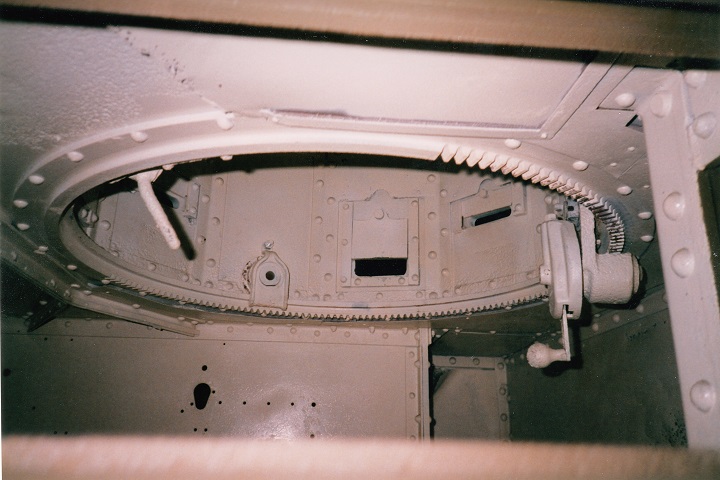
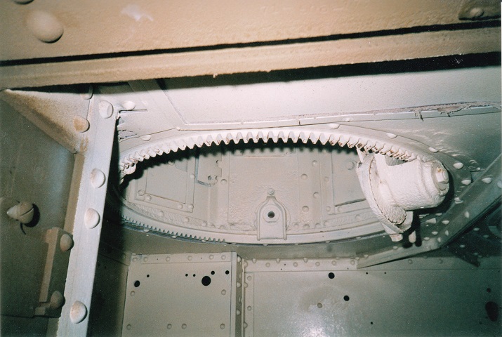
This is the commander's turret again, and the turret traverse mechanism can be seen here. The holes in the rear of the fighting compartment are for attaching various internal fixtures.
An internal view of the smaller .30cal machine gun turret is presented here. The rivets that hold the tank together are obvious throughout. Combat proved that rivets had the undesirable tendency to dislocate and fly around the interior when struck by hostile fire, and welding and casting took over as more common manufacturing methods.
The shape of the later, angular engine cover can be discerned in this image. The long pipes reaching across the rear deck from the air cleaners indicate that this is one of the tanks powered by a Guiberson diesel engine. (Picture from FM 30-40 C1 Military Intelligence Identification of United States Armored Vehicles.)
This M2A4 is externally very similar to the M3 Stuart. However, visible differences include the raised idler wheel, seven pistol ports ringing the turret compared with the M3's three, and the recoil mechanism of the 37mm gun extended from the gun shield and was therefore protected by armor. This tank apparently has its sponson machine guns fitted. This tank was in England in 1942 or 1943 and was part of a Lend-Lease shipment. (Library of Congress, Prints & Photographs Division, FSA-OWI Collection, reproduction number LC-USE6-D-009972 DLC. American Memory from the Library of Congress.)
Further details of the suspension and sponson machine gun can be seen here. The antiaircraft machine gun is mounted behind the commander's cupola. Note the antenna mount behind the engine's air cleaner. The long piping from the air cleaners indicates that this is one of the relatively few diesel-fueled M2A4s. (Picture from Development of Armored Vehicles, volume 1: Tanks.)
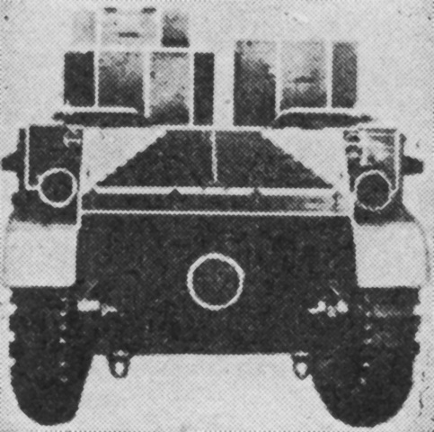
The driver's doors are closed on this tank, and details of the armor around the 37mm gun's recoil mechanism can be gleaned. This vehicle is the first M2A4 produced, and the armor for the recoil mechanism was later modified slightly, as in the tanks above. The bullet splash deflectors on the front hull that made their debut on this type of M2 can clearly be seen. (Picture from Tank Data, vol. 2.)
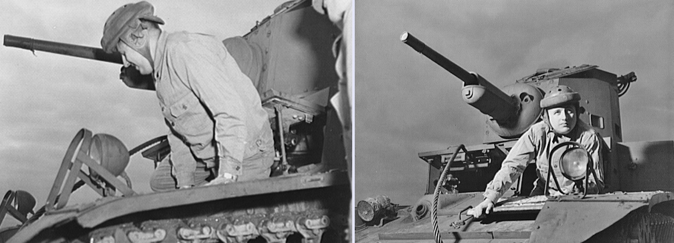
Here, Constantine P. Lihas demonstrates the dexterity needed to enter and exit the driver's position. (Picture taken in December 1942 by Gordon Parks; available from the Library of Congress.)
The right and left sides of the 37mm gun M5 are illustrated here. The gun's total weight was ~700lb (~310kg), with the barrel assembly weighing ~185lb (83.9kg). (Picture from FM 23-80 37-mm Gun, Tank, M5 (Mounted in Tanks).)
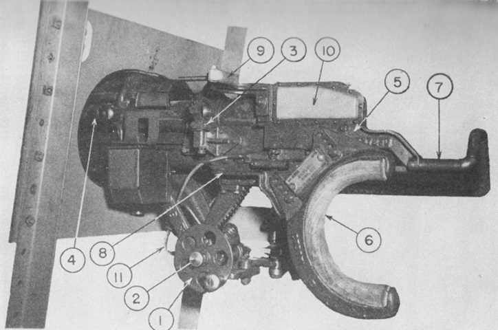
Here the gun is mounted in the combination mount M20 found in the M2A4. The gun mount could be disconnected from its elevation gears, and the gunner could then use the shoulder rest for free control. 1. Elevating handwheel. 2. 37-mm trigger actuator plunger. 3. Rear sight bracket (Wildrick sight adjusting bracket). 4. Front sight bracket. 5. Shoulder guard. 6. Shoulder rest. 7. Recoil guard. 8. Hand bracket (left). 9. Headrest (forward). 10. Headrest (right side). 11. 37-mm actuating cable. (Picture from FM 23-80 37-mm Gun, Tank, M5 (Mounted in Tanks).)
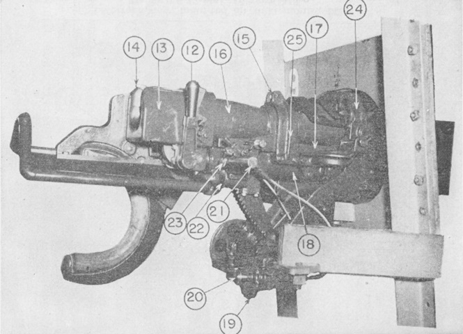
The opposite side of the combination gun mount M20 is shown here. The traversing handwheel was for the gun mount's 10° of traverse in each direction independent of the turret; the turret traverse was controlled by another handwheel on the commander/loader's side of the turret. When the traversing knob lock was loosened, the gunner could also use the shoulder rest to traverse the gun in the mount. 12. Operating handle. 13. Breech ring. 14. Cocking lever. 15. Traveling lock hook. 16. Barrel. 17. Cradle. 18. Recoil cylinder. 19. Traversing handwheel. 20. Caliber .30 machine gun trigger actuator plunger. 21. Hand bracket (right). 22. 37-mm trigger bar actuator. 23. Caliber .30 machine gun trigger actuator. 24. Trunnion. 25. Yoke. (Picture from FM 23-80 37-mm Gun, Tank, M5 (Mounted in Tanks).)
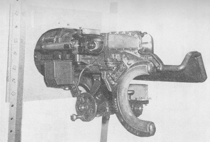
The telescope sight M5A1 is mounted in this image. (Picture from FM 23-80 37-mm Gun, Tank, M5 (Mounted in Tanks).)
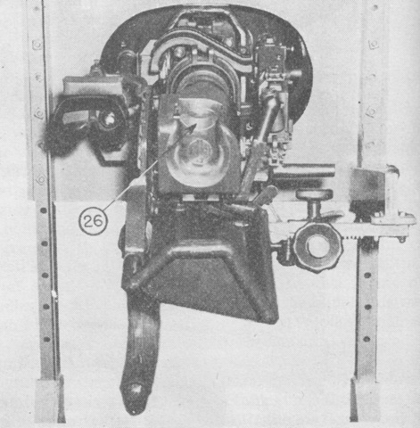
The gun and mount are seen from the rear. 26. Breechblock. (Picture from FM 23-80 37-mm Gun, Tank, M5 (Mounted in Tanks).)
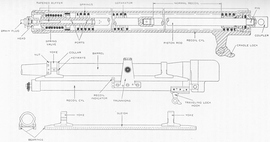
The hydrospring recoil cylinder is diagrammed at the top of this sketch. The sleigh at the bottom of the drawing was of built-up steel construction and mounted the gun in its yokes. The length of recoil was 8" (20cm), and there were 5 pints (2.4L) of oil in the cradle. (Picture from FM 23-80 37-mm Gun, Tank, M5 (Mounted in Tanks).)
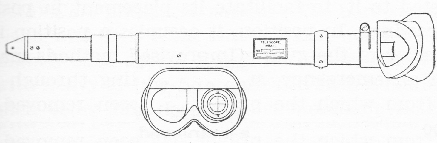
The telescope M5A1 had a magnification of 1-1.12 diameters and a field of 31°. The reticle was a simple crosshair etched into the sight. (Picture from FM 23-80 37-mm Gun, Tank, M5 (Mounted in Tanks).)
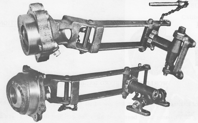
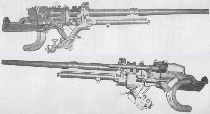
The 3.5" (8.9cm) fixed sponson ball machine gun mounts are seen removed from the tank. The left-hand mount is above, and the right-hand mount is at the bottom of the picture. The split spherical housing was bolted to the front of the sponson, and the rear of the cradle was bolted to the sponson interior. Once boresighted, the guns were fired via remote control, but traverse and elevation required manually adjusting the mounts. (Picture from Weapon Mounts for Secondary Armament.)
