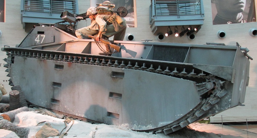
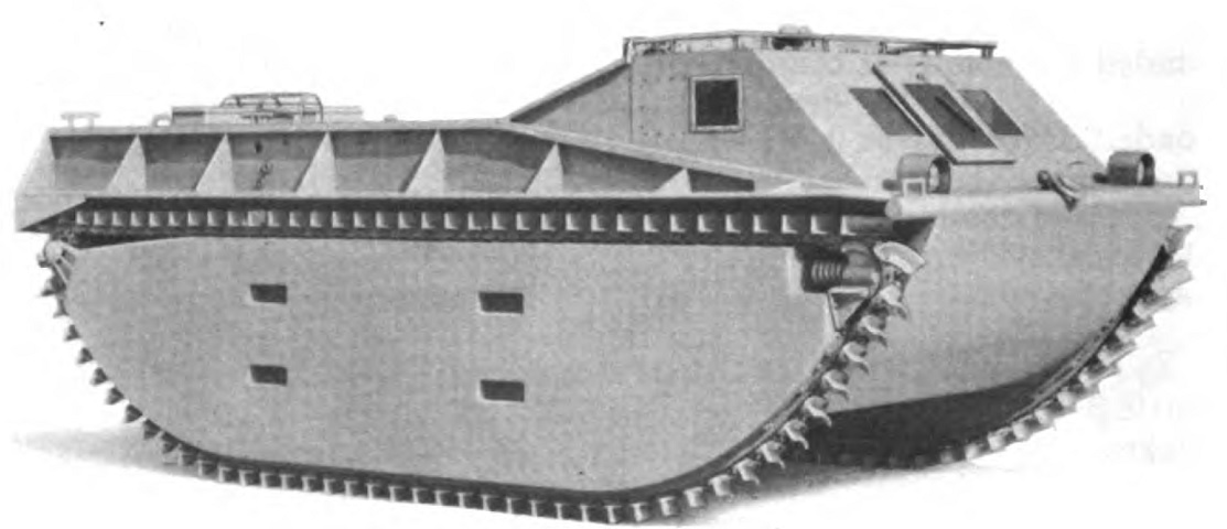
Landing Vehicle, Tracked, Mark 1 at the National Museum of the Marine Corps.
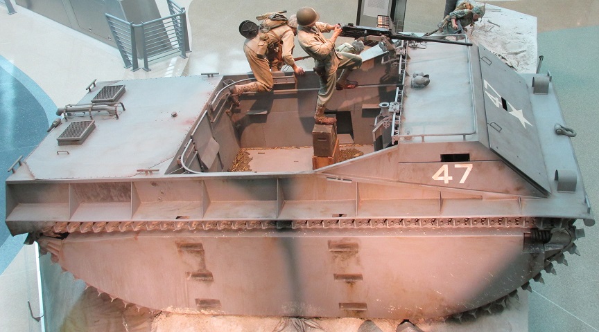
The consequences of the lack of a rear door on early amphibian tractors is played out in this diorama: The marines inside are forced to climb over the tall sides of the vehicle while under fire. The LVT1 was not conceived of as an assault vehicle, and the placement of the engine in the rear was not necessarily a detriment for supply transport, although a hoist would be required for heavy items. There are steps in the side pontoons, and applique armor has been added to the cab front and sides. A mesh screen for the engine compartment can be seen on the hull side behind the mooring tie.
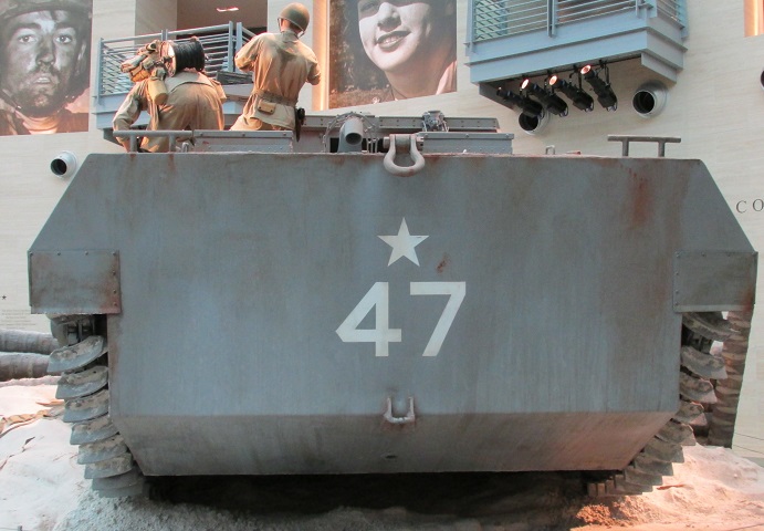
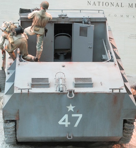
The engine exhaust pipe protruded over the rear of the hull, and mooring ties and a towing shackle can also be seen.
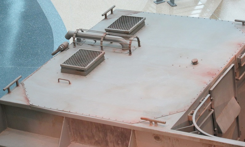
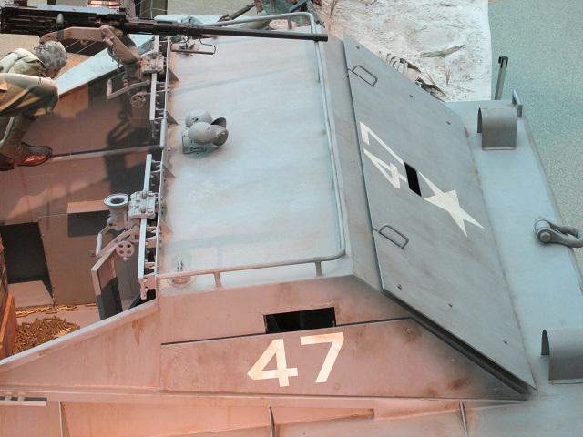
The engine deck is shown here, with the exhaust pipe, air grilles, and passenger compartment bulkhead access visible.
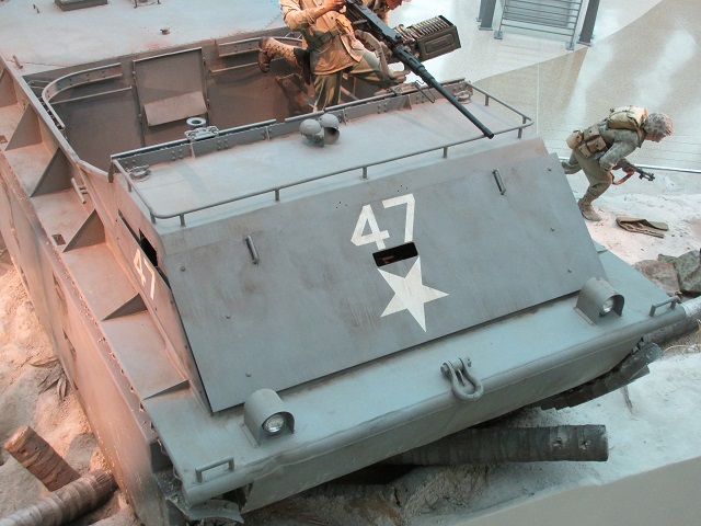
The positioning of the cab close to the bow differentiates the LVT1 from the LVT2 and LVT4. Details of the armor added to the cab front can be seen in this angle. There are three front windows in the cab, but the armor reduces forward visibility to a single vision slit. More mooring cleats are on the front corners of the hull.
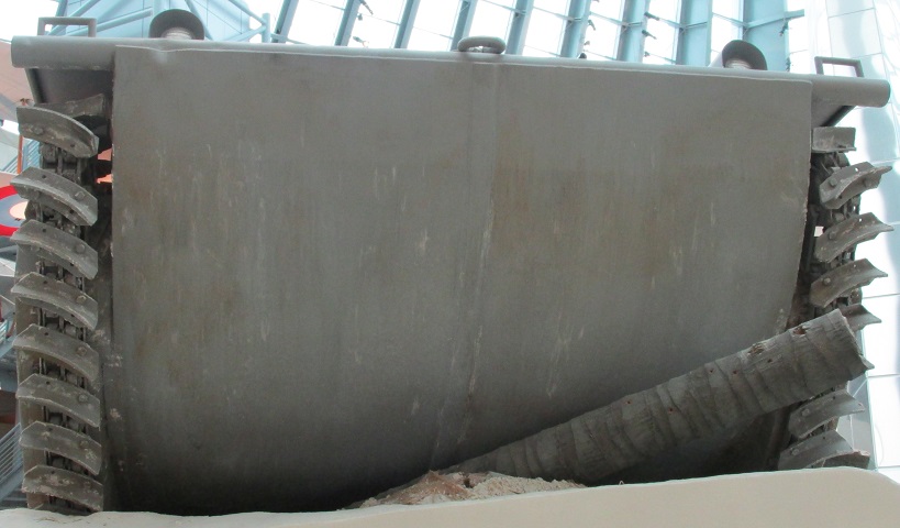
The smooth underside of the hull is shown here. The track's curved paddle grousers can be contrasted to later amphibian tractor track designs.
The size of the cargo and passenger compartment can be seen in this view.
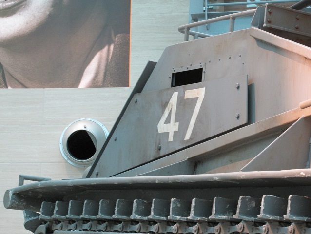
Details of the mounting of the applique armor on the cab sides can be seen here.
The front armor is also highlighted here; note the slots left for the grab handles on the cab front. The machine gun pintles and front skate rails can also be seen.
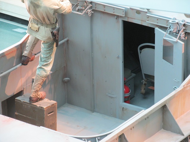
This view through the open cab door shows the red fire extinguisher bottle and seats mounted centrally and in the left rear corner.
A better view of the central driver's seat is provided here.
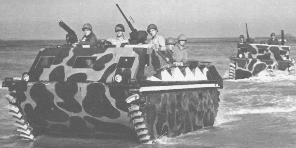
The wide spacing of the front windows marks this as an early production vehicle; on later production LVT1s the front windows were much closer together. (Picture from Tank Data, vol. 1.)
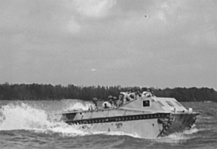
Another early tractor is seen underway in the New River in North Carolina. (Picture taken in May 1942 by Alfred T. Palmer; available from the Library of Congress.)
The spacing of the cab windows indicate this is a later production vehicle. (Picture from TM 9-2800 Standard Military Motor Vehicles.)
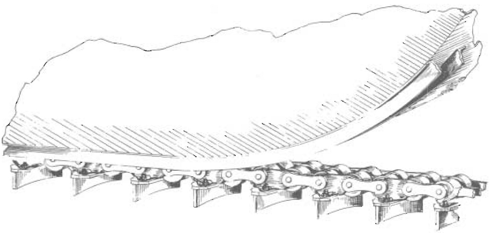
Details of the track construction and sponson channel for the roller bearings are diagrammed here. For illustrative purposes, the track does not wrap around the sponson in the image. (Picture from Research, Investigation and Experimentation in the Field of Amphibian Vehicles.)
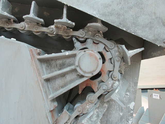
The rear drive sprocket is shown here.
Further details of the drive sprocket are shown, as well as the track's return run on top of the pontoon.
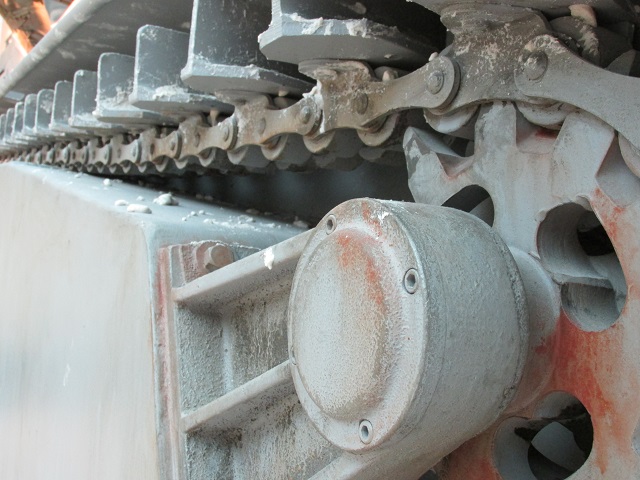
The sprocket teeth engaged the track rollers. The paddle grousers are also shown to good effect here.
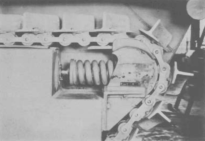
The construction of the idler block is shown here. Heavy-duty springs cushioned the blocks, and hydraulic ram pressure of ~1000psi (~70.20kg/cm²) was controlled via an hydraulic pump inside the cab. Note the flanges on top of the block that kept the tracks in line. (Picture from Research, Investigation and Experimentation in the Field of Amphibian Vehicles.)
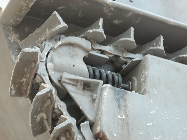
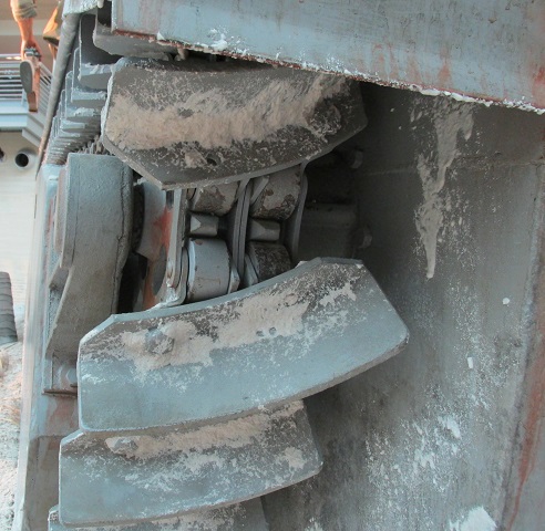
The idler block of the display vehicle is shown in this image.
