Landing Vehicle, Tracked (Armored), Mark 1.
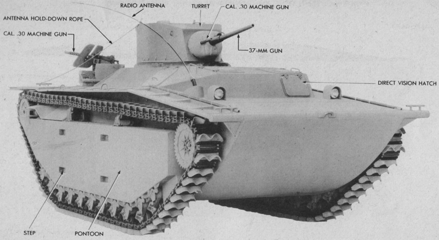
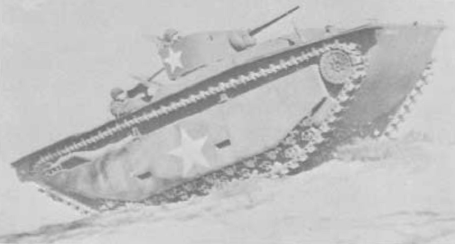
The 37mm gun turret perched on the back of the LVT(A)1 made for a tall vehicle. The track run circled the large side pontoons, and the positioning of one of the rear machine guns can be seen behind the turret. (Picture from TM 9-775 Landing Vehicle Tracked Mk. I and Mk. II.)
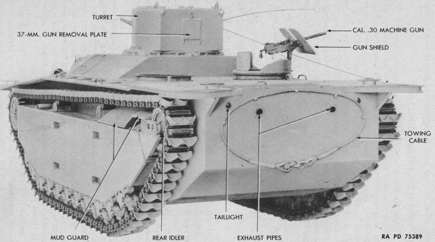
Note that only one of the rear machine gun mounts is installed in this image. (Picture from TM 9-775 Landing Vehicle Tracked Mk. I and Mk. II.)
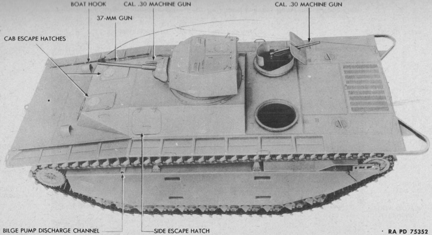
Especially when seen from above, the basis on the LVT(A)2 is obvious. (Picture from TM 9-775 Landing Vehicle Tracked Mk. I and Mk. II.)
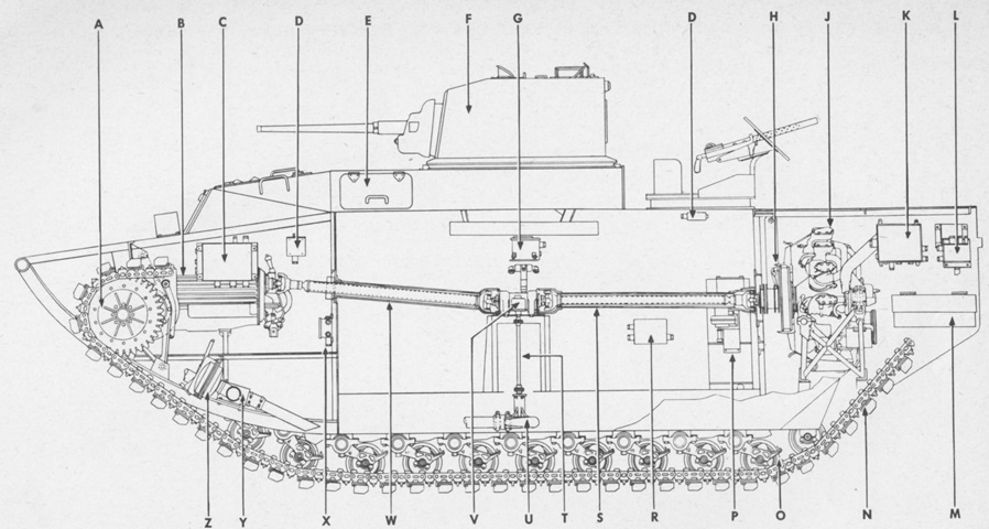
The automotive layout can be seen in this cross-section, along with the turret basket. Power from the rear engine was transferred to the front transmission via propeller shafts, and a power takeoff ran the bilge pump at the floor of the hull. The letters refer to a part number list. (Picture from ORD 9 SNL G-214.)
The rear machine gunners were provided with shields, but were still quite exposed compared to the turret crew. (Picture from Research, Investigation and Experimentation in the Field of Amphibian Vehicles.)
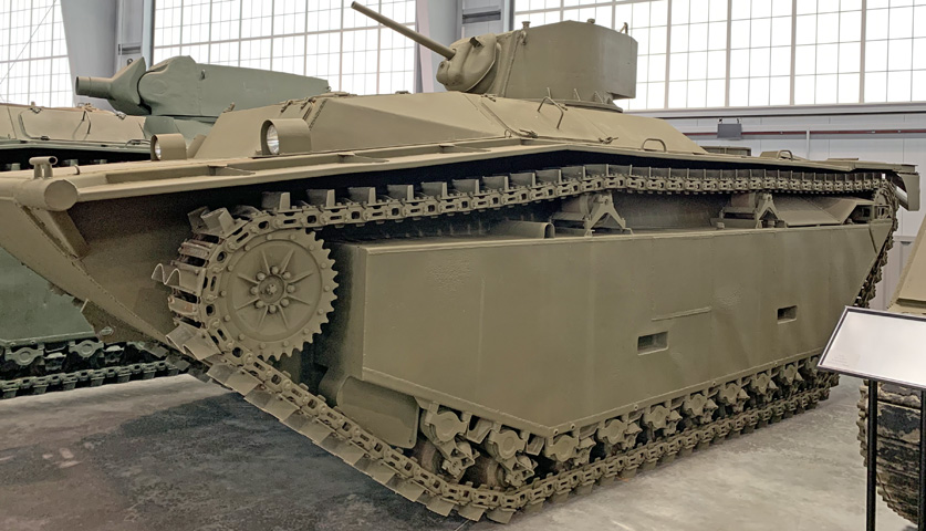
The shape of the propeller-like grousers can be better seen here. The driver had a direct-vision hatch in the front left corner of the cab, behind the left headlight in this view. Mooring ties are mounted on each corner of the hull. A side escape hatch can be seen on the sloping plate above the front return roller.
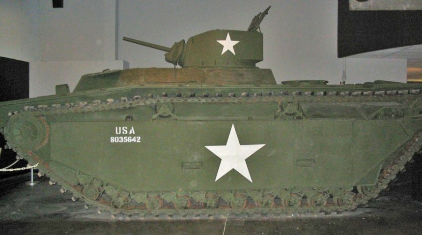
This side view illustrates the numerous road wheels sprung by the torsilastic suspension. The two track return rollers are apparent, and behind the rear return roller was a mud guard that extended back to the toothed idler wheel. The turret doors are open, increasing the machine's already considerable height.
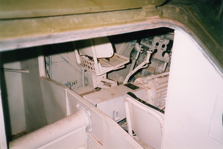
A view through the open right hull escape hatch shows the driver's position. The steering levers are topped by black handles, and the gearshift lever is all white. The driver's instrument panel is situated directly in front of his seat. The transmission separates the drivers, and the propeller shaft can be seen leading from the engine in the rear of the vehicle. A radio cabinet was just to the right of the assistant driver, and the bilge pump handle was positioned directly in front of his seat.
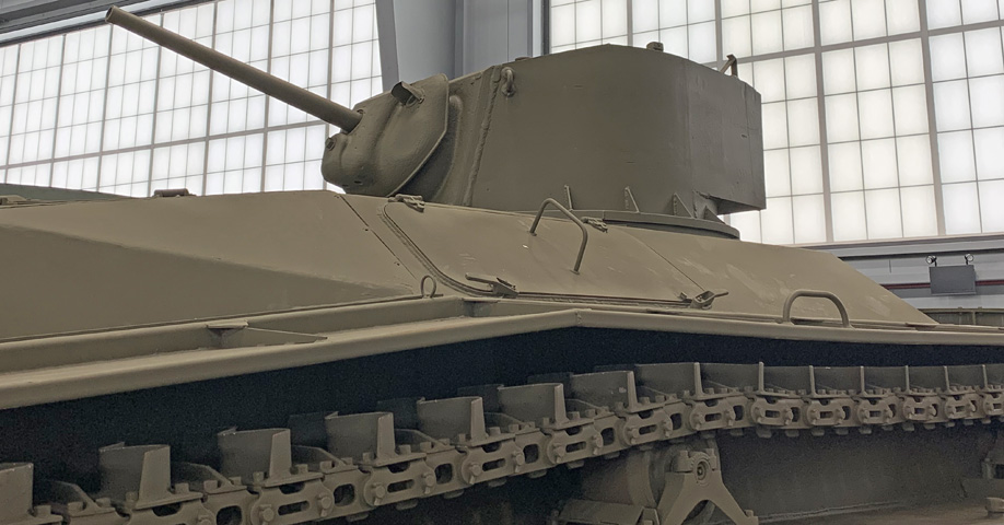
A closer view of the turret and side escape hatch is provided here. The cylindrical shield typically found at the base of the gun tube is not present on this example.
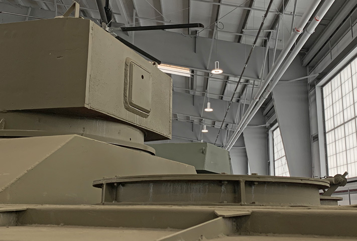
This rear view of the turret shows the 37mm gun removal plate as well as one of the bases for the rear .30cal machine guns.
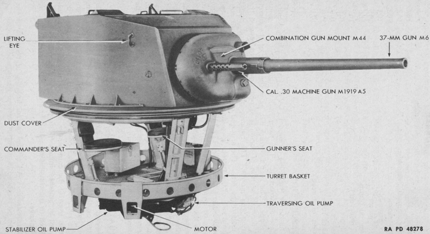
The turret is shown here with its basket attached. Like on the light tank M5, the power traversing equipment is mounted under the basket. (Picture from TM 9-775 Landing Vehicle Tracked Mk. I and Mk. II.)
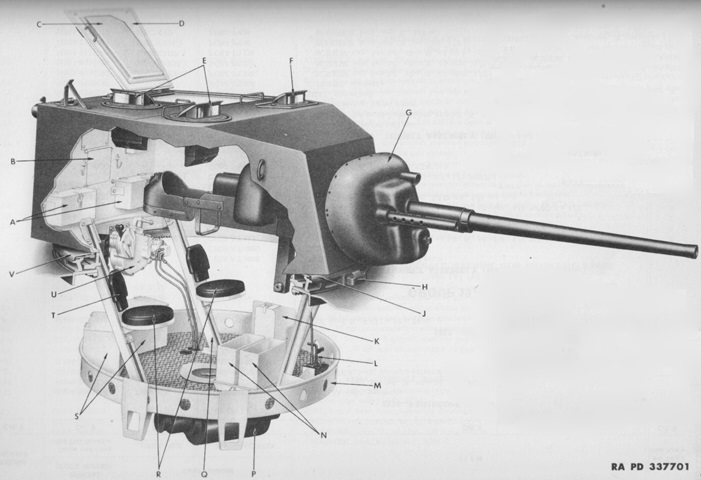
The general layout of the turret can be seen in this image. Although generally resembling the turret found on the light tank M5, the LVT(A)1's was more thinly armored. (Picture from ORD 9 SNL G-214.)
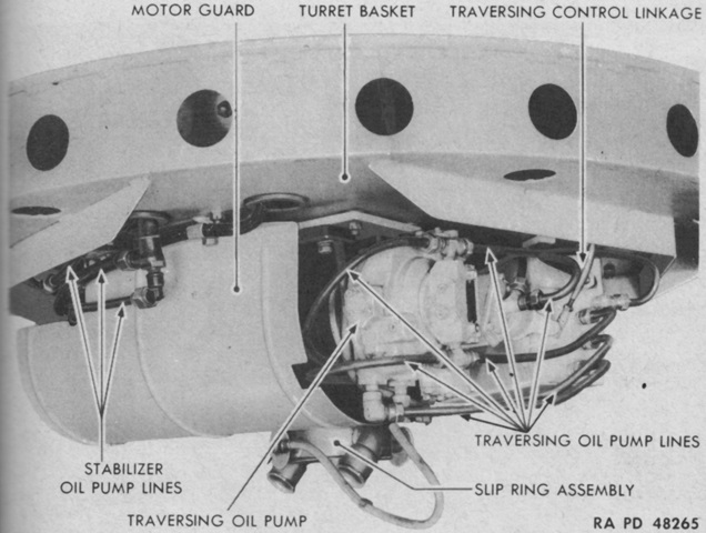
The machinery attached to the underside of the turret basket can be seen here. (Picture from TM 9-775 Landing Vehicle Tracked Mk. I and Mk. II.)
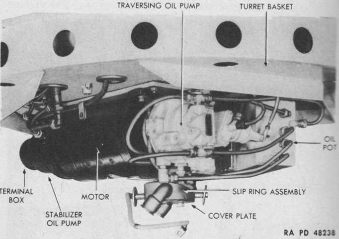
The motor guard has been removed, providing a view of the oil pump motor and other components normally hidden by the guard. (Picture from TM 9-775 Landing Vehicle Tracked Mk. I and Mk. II.)
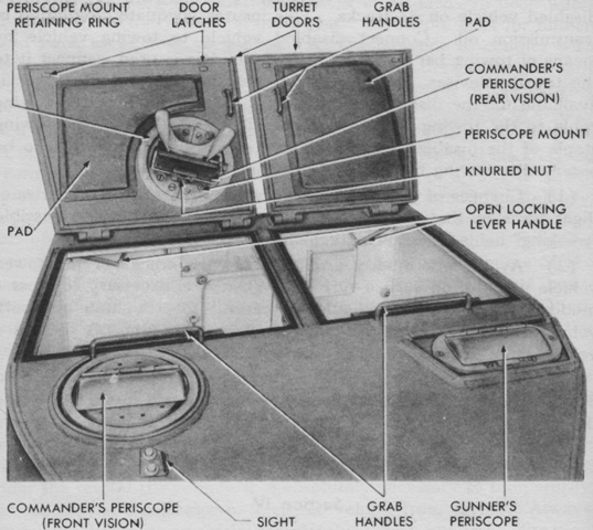
This image is of the turret roof, facing rearwards. The commander was provided with a periscope in his hatch door as well as one forward in the turret roof. (Picture from TM 9-775 Landing Vehicle Tracked Mk. I and Mk. II.)
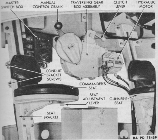
A closer view of the turret basket interior is provided here. (Picture from TM 9-775 Landing Vehicle Tracked Mk. I and Mk. II.)
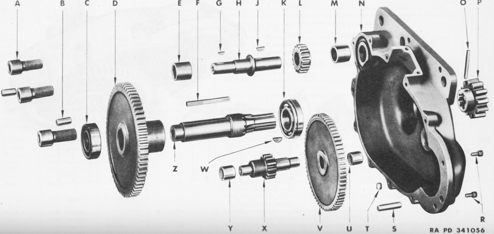
This diagram is an exploded view of the traversing gear box assembly visible in the above image. (Picture from ORD 9 SNL G-214.)
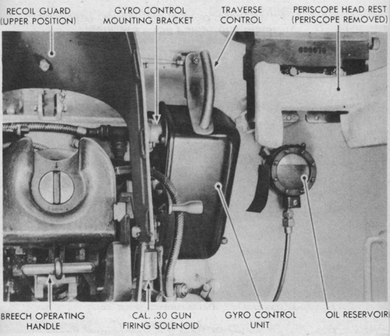
The front of the gunner's side of the turret is shown in this image. (Picture from TM 9-775 Landing Vehicle Tracked Mk. I and Mk. II.)
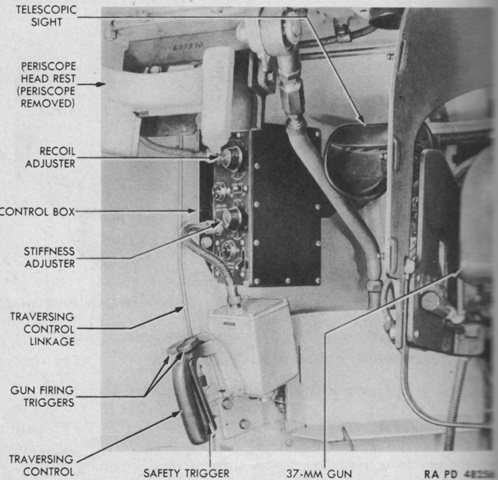
Instruments and controls in the right front of the turret are labeled here. (Picture from TM 9-775 Landing Vehicle Tracked Mk. I and Mk. II.)
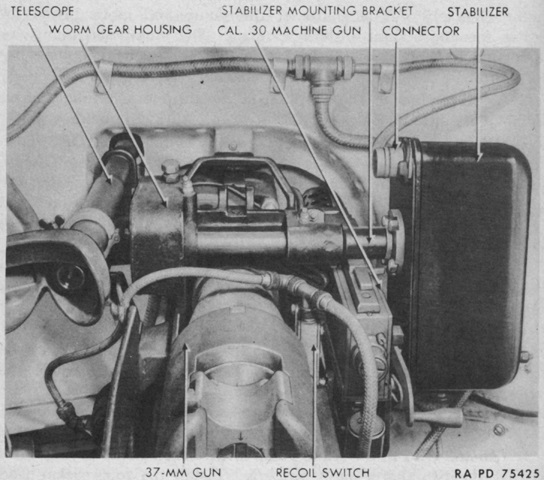
The location of the elevation stabilizer in relation to the main gun can be seen here. The cable going to the labeled connector has been removed. (Picture from TM 9-775 Landing Vehicle Tracked Mk. I and Mk. II.)
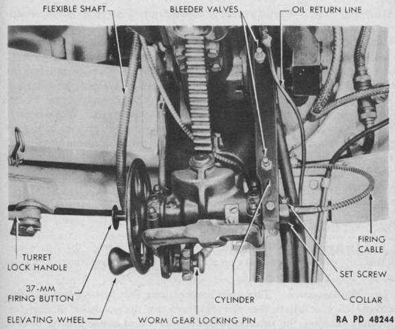
The stabilizer connected to the elevation gear via the cylinder shown here. (Picture from TM 9-775 Landing Vehicle Tracked Mk. I and Mk. II.)
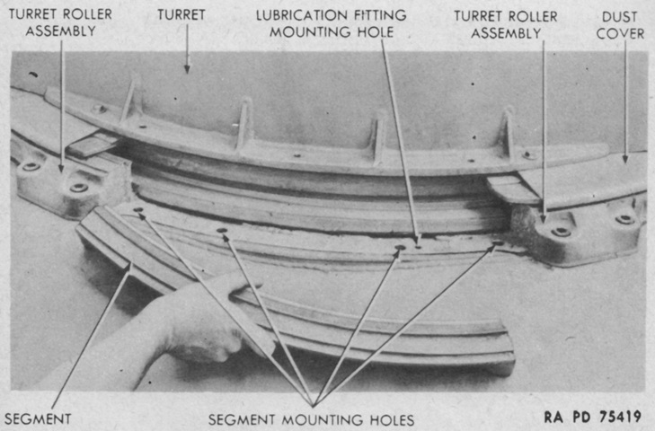
The turret was secured to the vehicle via six roller assemblies and six segments, which were protected by a dust cover. One of the segments is shown here just after being removed. (Picture from TM 9-775 Landing Vehicle Tracked Mk. I and Mk. II.)
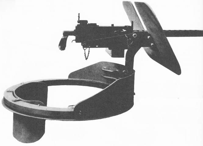
The Mark 21 caliber .30 concentric ring mount is shown dismounted from the tractor. The gunner was provided with a back rest for support. (Picture from Weapon Mounts for Secondary Armament.)
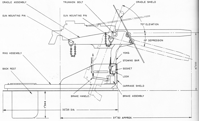
A schematic of the Mark 21 mount is drawn in this image. (Picture from Weapon Mounts for Secondary Armament.)
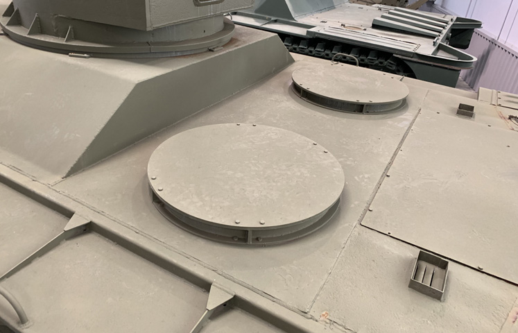
The bases for the Mark 21 mounts have been covered on this machine, but their locations as well as details of the turret segments and rollers can be seen.
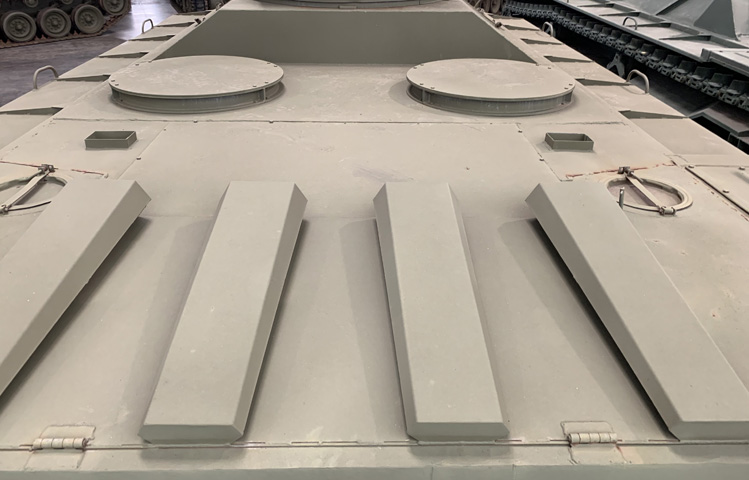
Armored louvres protect the air exhausts on the hinged engine room hatch, which is a feature not found on the early-production vehicle illustrated above in the technical manual.
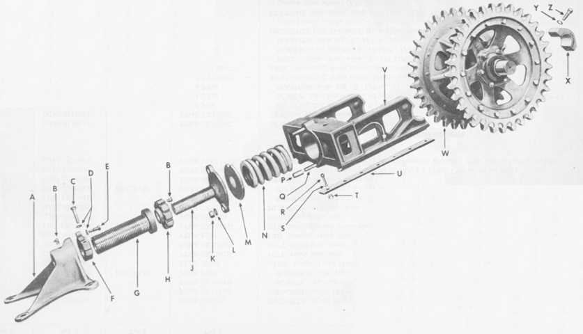
A parts diagram of the rear idler is the subject of this picture. (Picture from ORD 9 SNL G-214.)
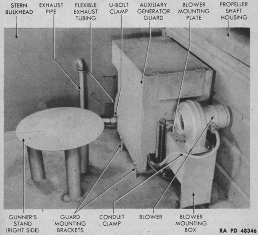
A DR 7812 one-cylinder, air-cooled, gasoline auxiliary generator was mounted on the right side of the control tunnel in front of the stern bulkhead. The blower provided air circulation and dispersed exhaust fumes. A 1gal (3.8L) armored fuel tank was installed above the fixed fire extinguishers to feed the generator engine. (Picture from TM 9-775 Landing Vehicle Tracked Mk. I and Mk. II.)
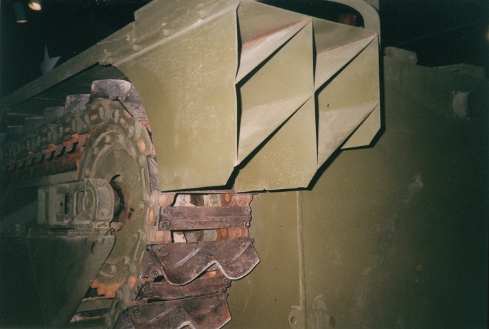
Details of the track and assembled idler are visible here. The track was essentially two chains composed of inner and outer links. The inner links were connected by steel cross plates, and the outer links by the grousers and the grouser support plates. The idler wheel was toothed, and the teeth on this wheel are rusty in color. The idler adjustment mechanism changed from LVT1 to LVT2, upon which the LVT(A)1 was ultimately based. LVT1 used an hydraulic jack, while LVT2 used the adjustment bracket seen here. The structures behind the tracks are splash deflectors.
