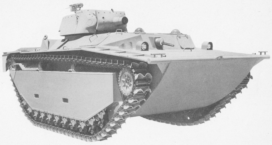
Landing Vehicle, Tracked (Armored), Mark 4.
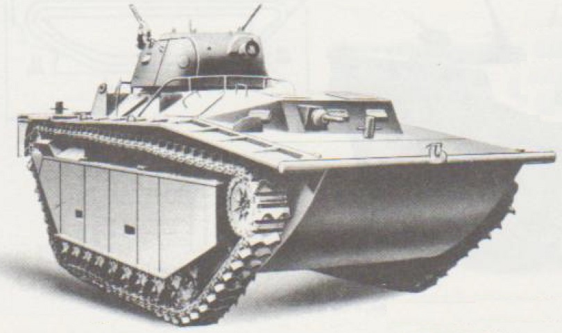
This machine has the bow machine gun at the assistant driver's position but retains the plastic hemispheres around the drivers' periscopes. A single .50cal machine gun is mounted at the rear of the turret, which resembled that of the 75mm HMC M8. (Picture from ORD 9 SNL G-214.)
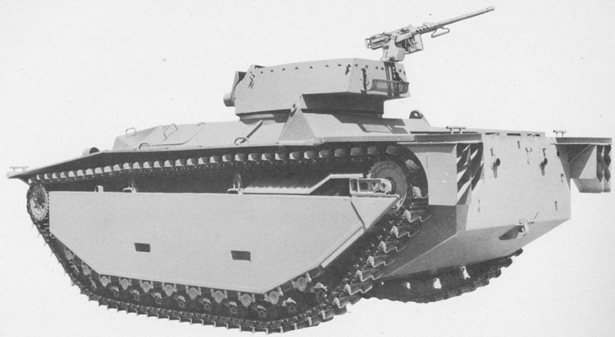
A better view of the machine gun mount can be seen from this angle. Apertures for the two engine exhaust pipes can be seen in the hull rear. (Picture from ORD 9 SNL G-214.)
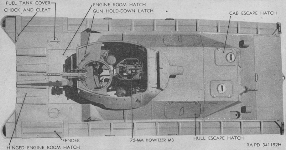
The machine gun ring mount is obvious at the turret's right rear, and the gunner's and loader's seats can be seen at the howitzer's right and left, respectively. Note the offset nature of the drivers' hatches. (Picture from TM 9-775 Tracked Landing Vehicle Mk 4 (LVT(4)) Tracked Landing Vehicles (Armored) Mk 4 (LVT(A)(4)) and Mk 5 (LVT(A)(5)).)
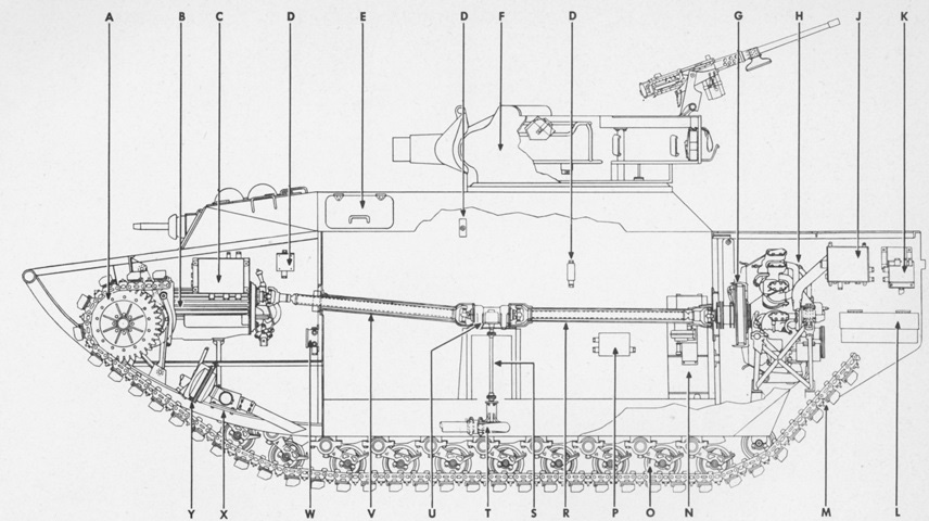
The automotive layout of the machine is sketched in this image. Power from the rear engine was transferred to the front transmission via propeller shafts, and a power takeoff ran the bilge pump at the floor of the hull. The assistant driver was also provided with a manual bilge pump for emergencies. The letters refer to a part number list. (Picture from ORD 9 SNL G-214.)
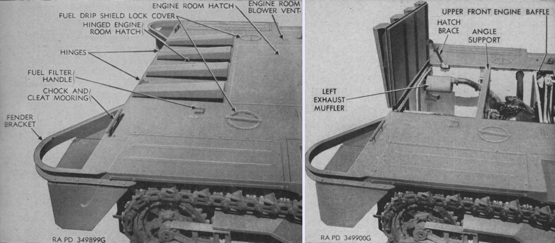
Details of the rear deck are shown in this picture, closed on the left and open on the right. (Picture from TM 9-775 Tracked Landing Vehicle Mk 4 (LVT(4)) Tracked Landing Vehicles (Armored) Mk 4 (LVT(A)(4)) and Mk 5 (LVT(A)(5)).)
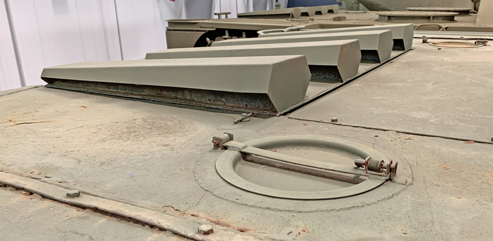
A closer look at the engine hatch and its louvres is provided here.
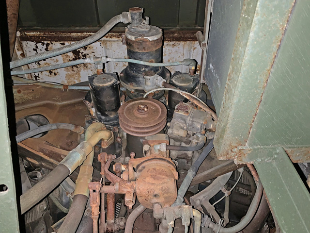
The rear of the engine is seen from below; the engine room hatch can be seen painted green at the top of the picture. The pulley in the central portion of the image is the generator drive pulley; its missing belt would normally extend to the pulley's lower left. The fuel tank for the auxiliary generator engine is installed on the pedestal at the right.
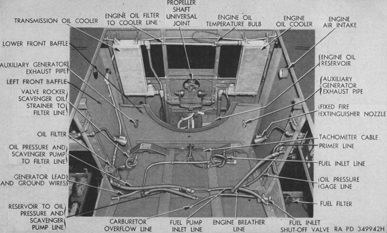
The engine compartment is seen here with the engine itself removed. (Picture from TM 9-775 Tracked Landing Vehicle Mk 4 (LVT(4)) Tracked Landing Vehicles (Armored) Mk 4 (LVT(A)(4)) and Mk 5 (LVT(A)(5)).)
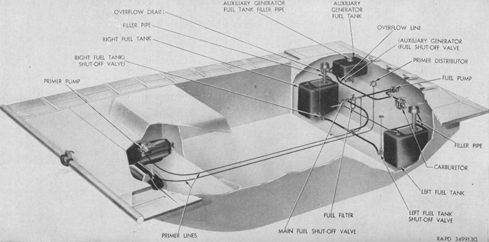
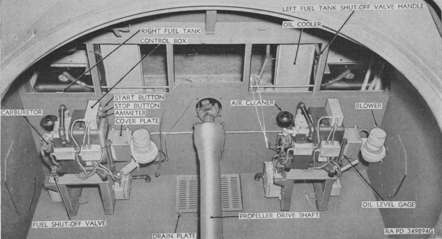
The two main engine fuel tanks were on each side of the engine room, the left in front of the batteries and the right in front of the fixed fire extinguishers. The fuel tank for the auxiliary generator engine was on the right above the fire extinguishers. (Picture from TM 9-775 Tracked Landing Vehicle Mk 4 (LVT(4)) Tracked Landing Vehicles (Armored) Mk 4 (LVT(A)(4)) and Mk 5 (LVT(A)(5)).)
The 75mm howitzer M3 could use fixed or semifixed ammunition. It had a manually operated horizontally sliding breech and a continuous-pull type of firing lock, which could be actuated manually or electrically. It weighed 421lb (191kg). The howitzer mount M7 used a hydrospring recoil mechanism with a normal recoil stroke of 11.62" (29.51cm). (Picture from TM 9-775 Tracked Landing Vehicle Mk 4 (LVT(4)) Tracked Landing Vehicles (Armored) Mk 4 (LVT(A)(4)) and Mk 5 (LVT(A)(5)).)
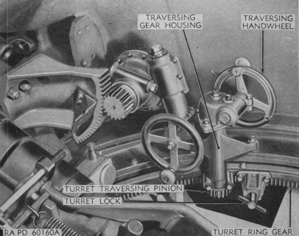
The turret traversing mechanism is labeled in this image. (Picture from TM 9-775 Tracked Landing Vehicle Mk 4 (LVT(4)) Tracked Landing Vehicles (Armored) Mk 4 (LVT(A)(4)) and Mk 5 (LVT(A)(5)).)
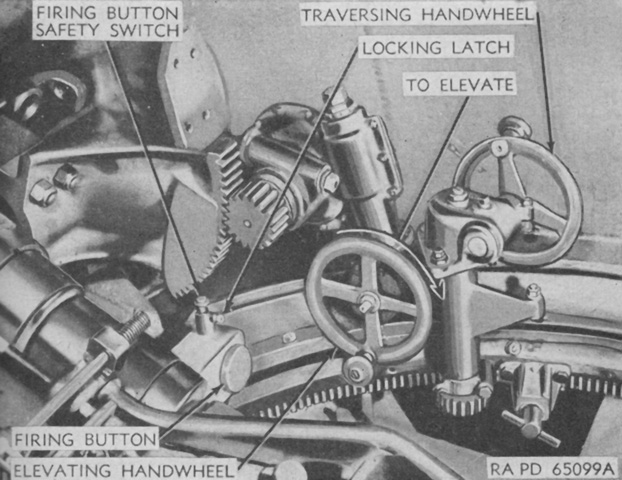
The elevation mechanism and howitzer firing button are the subjects of this picture. The firing button safety switch prevented the howitzer from firing when the switch was in the "OFF" or down position. When in the "ON" or up position, the firing button was freed. In order to move the safety switch, the locking latch needed to be pressed. (Picture from TM 9-775 Tracked Landing Vehicle Mk 4 (LVT(4)) Tracked Landing Vehicles (Armored) Mk 4 (LVT(A)(4)) and Mk 5 (LVT(A)(5)).)
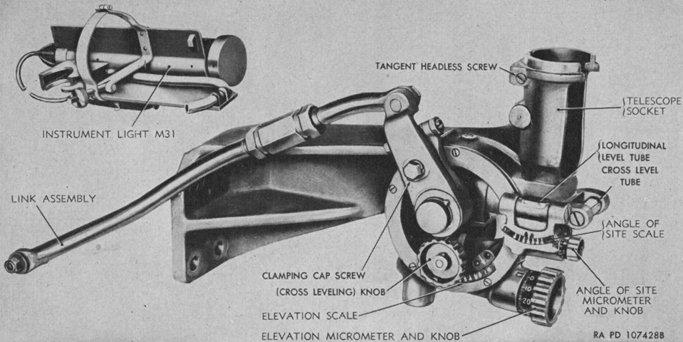
The panoramic telescope M12A5 was common to the 75mm howitzer motor carriage M8, and could be installed in either the telescope mount M44 or M44A1. The M44A1 seen here was identical to the M44 except for the lack of a range drum. (Picture from TM 9-775 Tracked Landing Vehicle Mk 4 (LVT(4)) Tracked Landing Vehicles (Armored) Mk 4 (LVT(A)(4)) and Mk 5 (LVT(A)(5)).)
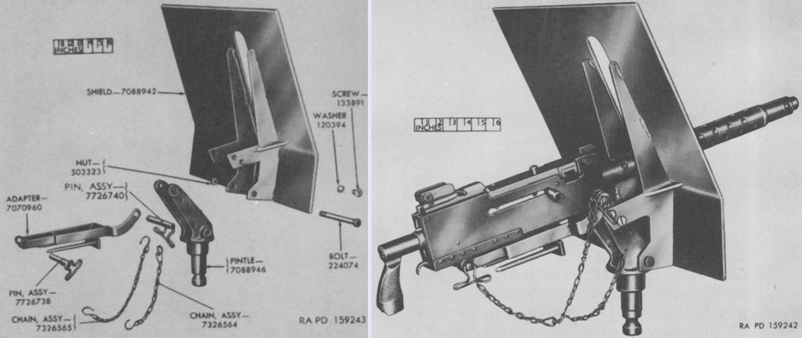
The pintle and shield assembly 7326774 could be used with the later turret-mounted machine guns. The shield was attached to the pintle with three bolts, and the adapter was provided with two attachments for an expended casing bag. (Picture from Weapon Mounts for Secondary Armament.)
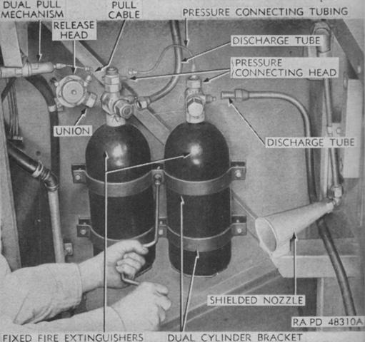
Two 10lb (4.5kg) CO2 fixed fire extinguishers were located in the pontoon to the right of the engine compartment; their contents were discharged through six nozzles in the engine compartment. Two remote control handles actuated the cylinders, one on the engine front bulkhead in the cargo compartment between the right-hand louvres, and the second in the upper left corner of the cab above the assistant driver. A 15lb (6.8kg) CO2 portable extinguisher was stowed on the floor of the cab to the driver's left. (Picture from TM 9-775 Tracked Landing Vehicle Mk 4 (LVT(4)) Tracked Landing Vehicles (Armored) Mk 4 (LVT(A)(4)) and Mk 5 (LVT(A)(5)).)
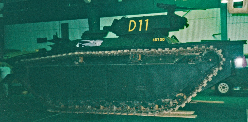
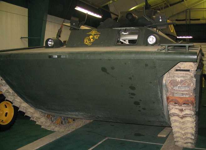
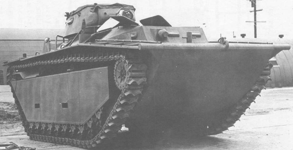
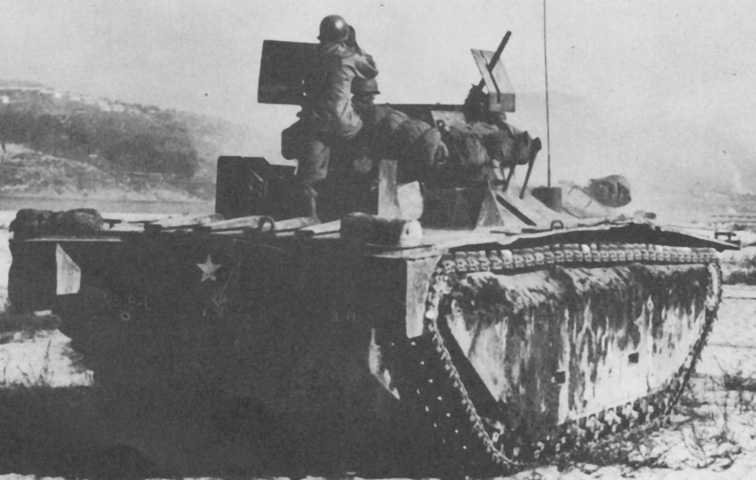
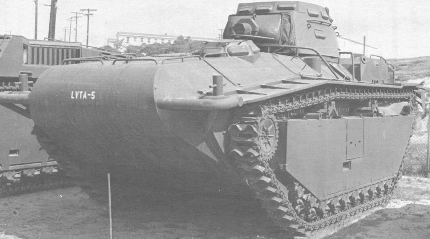
This is an earlier-production LVT(A)4, as evidenced by the single .50cal MG mount on the turret rear. The propelling grousers on the track are obvious, and a hull escape hatch is open near the cab.
The hatches are open on this vehicle. The driver was provided with a direct vision hatch to his front, and both he and the assistant driver had periscopes in their overhead hatches. The lack of a bow machine gun in front of the assistant driver is obvious in this view, as is the paddle design of the track grousers. Mooring ties were provided at each corner of the hull.
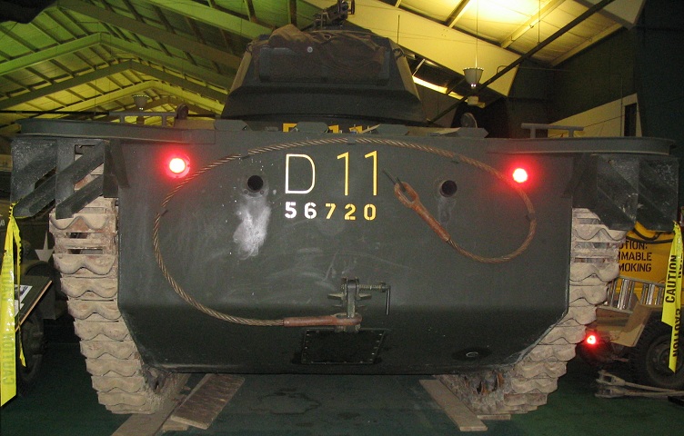
The exhaust tips for the radial engine flank the numbering on the rear of the hull, and the glare of the taillights can be seen outboard of the exhausts. Stowage for a towing cable is also provided. Splash deflectors are just behind each track.
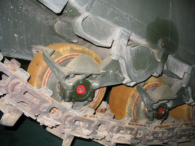
A close-up of the suspension is shown in this image. The torsilastic suspension was composed of rubber bonded between the hollow shaft on the pontoon and the outer road wheel swing arm. Details of the chain-type track can also be seen.
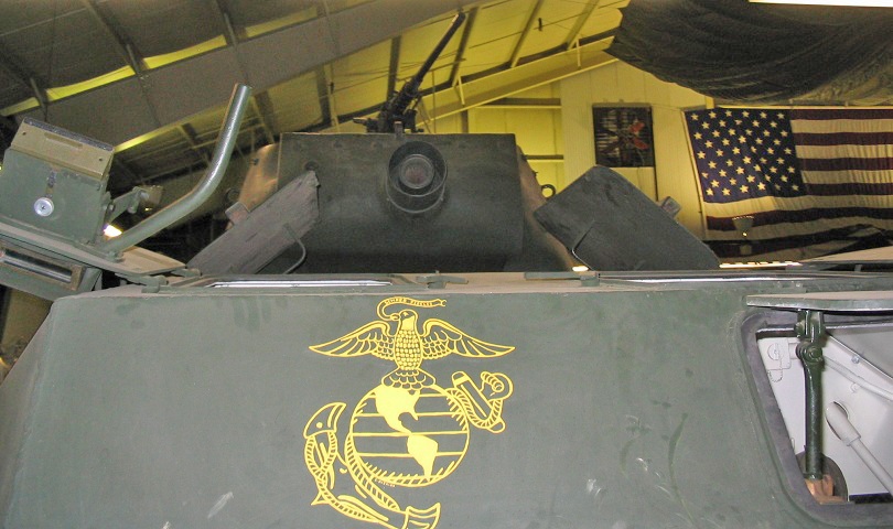
The 75mm howitzer was encased in a flash suppressor, and the howitzer barrel can be seen inside the suppressor. The .50cal MG is mounted on the turret rear, and details of the drivers' hatches and periscopes can be seen.
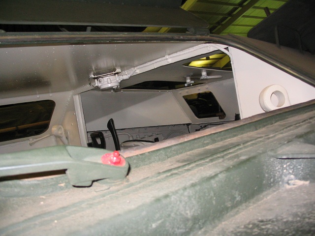
When all the hatches were open, the vehicle interior was a decently airy place. This view is looking in from the starboard hull escape hatch towards the driver's position.
This vehicle features vision blocks in the turret side, and the angular counterweight attached to the top of the howitzer flash hider can just be seen behind the assistant driver's periscope. (Picture from Tank Data, vol. 2.)
The machine guns mounted on each side of the turret are illustrated by this vehicle. The counterweight for the stabilizer can again be seen. (Picture from TM 9-2800-1/TO 19-75A-89.)
A view from the opposite angle is provided in this image with a clearer view of the counterweight. (Picture from TM 9-775 Tracked Landing Vehicle Mk 4 (LVT(4)) Tracked Landing Vehicles (Armored) Mk 4 (LVT(A)(4)) and Mk 5 (LVT(A)(5)).)
The turret machine guns on this tractor are fitted with the pintle and shield assembly 7326774. (Picture from Weapon Mounts for Secondary Armament.)
The two auxiliary generators are shown here; on LVT(A)4 only the right-side generator was mounted. The engines could be started either electrically or by pulling a cranking rope. The engine was a Delco Appliance Corporation No. 5067440 single-cylinder 4-cycle gasoline engine putting out 1.6hp at 2,300rpm. (Picture from TM 9-775 Tracked Landing Vehicle Mk 4 (LVT(4)) Tracked Landing Vehicles (Armored) Mk 4 (LVT(A)(4)) and Mk 5 (LVT(A)(5)).)
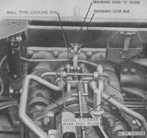
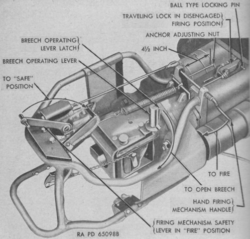
To disengage the howitzer travel lock, the ordnance was depressed slightly to relieve pressure on the lock and to remove the ball type locking pin. The howitzer was then further depressed until the traveling lock bar fell forward to the disengaged or firing position. Once in that position the bar was secured by the insertion of a locking pin. (Picture from TM 9-775 Tracked Landing Vehicle Mk 4 (LVT(4)) Tracked Landing Vehicles (Armored) Mk 4 (LVT(A)(4)) and Mk 5 (LVT(A)(5)).)
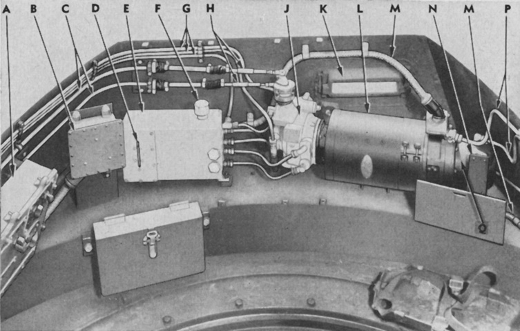
Parts of the turret hydraulic system are labeled in this image. A. Turret panel control box. B. Remote control box. C. Traverse control tubes. D. Oil reservoir gage. E. Traversing oil reservoir. F. Reservoir filler cap. G. Hydraulic traversing oil lines. H. Valve control arms. J. Traversing oil pump. K. Vision block. L. Electric motor. M. Conduit to motor and gyro-stabilizer. N. Inspection plate. P. Stabilizer hydraulic lines. Q. Stabilizer oil pump. (Picture from TM 9-775 Tracked Landing Vehicle Mk 4 (LVT(4)) Tracked Landing Vehicles (Armored) Mk 4 (LVT(A)(4)) and Mk 5 (LVT(A)(5)).)
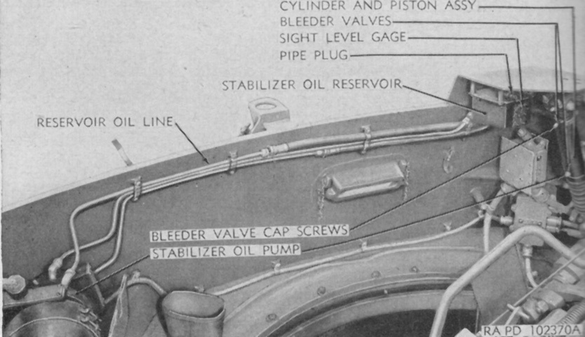
The oil lines and reservoir for the stabilizer system are shown here. (Picture from TM 9-775 Tracked Landing Vehicle Mk 4 (LVT(4)) Tracked Landing Vehicles (Armored) Mk 4 (LVT(A)(4)) and Mk 5 (LVT(A)(5)).)
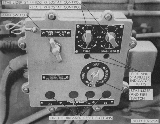
The turret panel control box allowed the hydraulic power traversing mechanism oil pump and the stabilizer oil pump electric motors to be turned on and off via the main switch. The recoil and stiffness rheostats adjusted the stabilizer's sensitivity in recoil and elevation. The stiffness rheostat could also account for differences in oil viscosity and electrical current. The stabilizer-and-fire switch controlled the firing circuit and stabilizer system: these could be both off, both on, or activated separately. (Picture from TM 9-775 Tracked Landing Vehicle Mk 4 (LVT(4)) Tracked Landing Vehicles (Armored) Mk 4 (LVT(A)(4)) and Mk 5 (LVT(A)(5)).)
An overview of the right side of the turret is detailed in this image. (Picture from TM 9-775 Tracked Landing Vehicle Mk 4 (LVT(4)) Tracked Landing Vehicles (Armored) Mk 4 (LVT(A)(4)) and Mk 5 (LVT(A)(5)).)
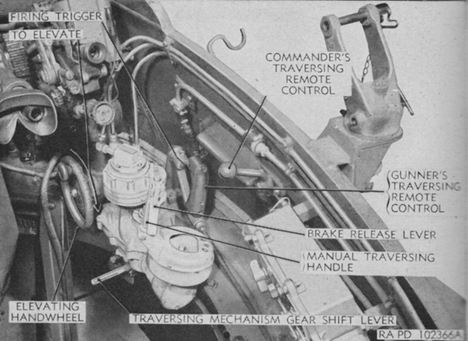
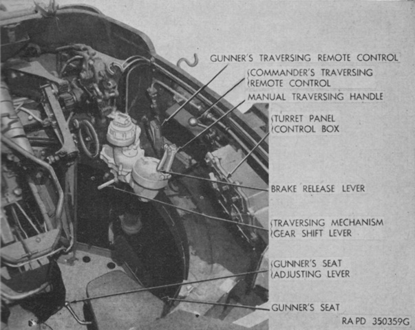
The gunner's and commander's controls are shown here. The traversing mechanism gear shift lever allowed either manual or power traverse to be selected; when hydraulic power was active, the commander's traversing remote control overrode the gunner's traversing remote control. The gunner's remote control was provided with triggers for firing the howitzer. For manual turret traverse, the brake release lever needed to be squeezed in order to release the turret brake. (Picture from TM 9-775 Tracked Landing Vehicle Mk 4 (LVT(4)) Tracked Landing Vehicles (Armored) Mk 4 (LVT(A)(4)) and Mk 5 (LVT(A)(5)).)
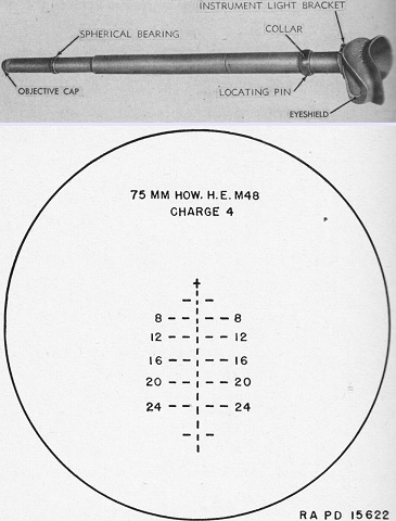
The telescope M70R was identical to the M70C except for being 12" (30cm) longer. The reticle pattern was calibrated for the 75mm howitzer high-explosive shell M48 fired at charge 4 with a muzzle velocity of 1,250 feet/sec (381m/s) and a plus 1.0-mil jump. Each of the vertical lines and spaces of the broken center line represented 100 yards (91m), while the broken horizontal lines were ranges in hundreds of yards. Each horizontal line and space was a 5-mil deflection. The zero-range and zero-deflection cross was used for boresighting. (Picture from TM 9-775 Tracked Landing Vehicle Mk 4 (LVT(4)) Tracked Landing Vehicles (Armored) Mk 4 (LVT(A)(4)) and Mk 5 (LVT(A)(5)).)
The 1951 modification to the bow of the vehicle is obvious when compared to the machines above: the bow's volume was increased, and the driver was given a vision cupola. The turret was also changed, and new vision blocks can be seen around its top. Note the counterweight attached to the base of the howitzer barrel for the stabilizer system. (Picture from Tank Data, vol. 2.)
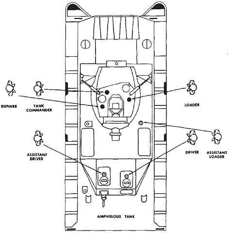
The crew positions are shown here. (Picture from FM 17-34 Amphibious Tank and Tractor Battalions.)
