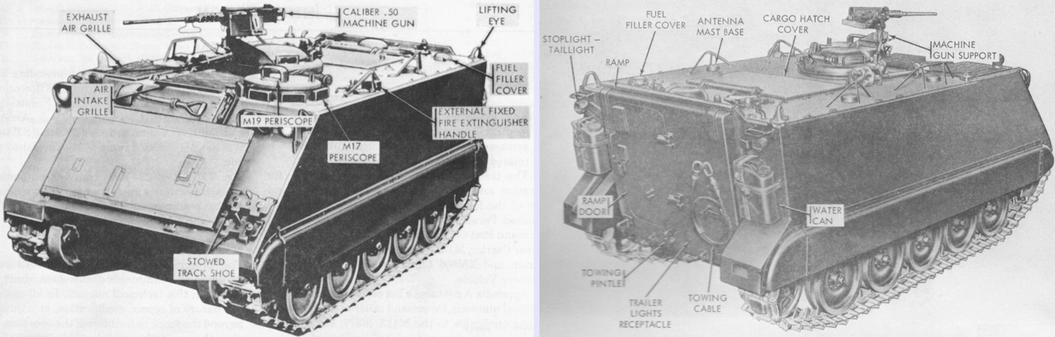
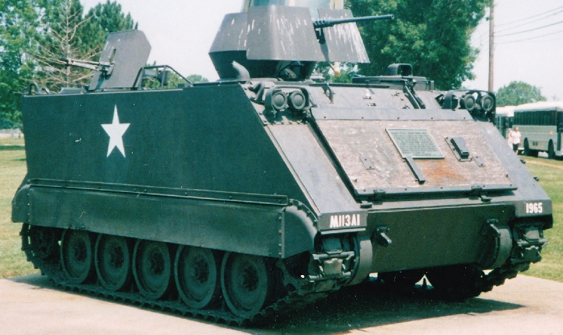
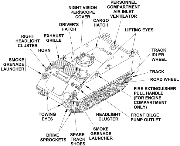
Armored Personnel Carrier M113.
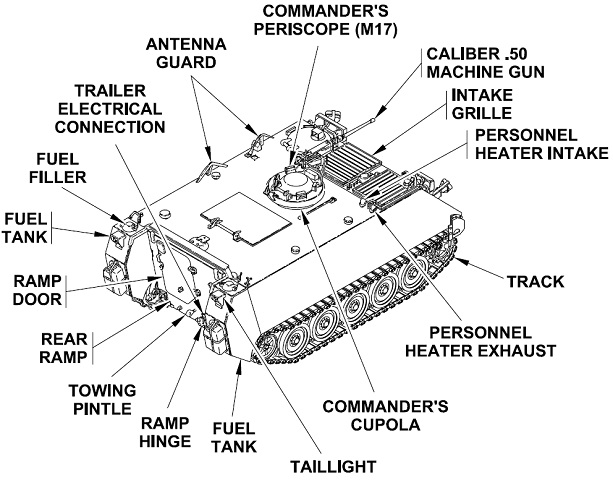
The vehicle is seen here from the left front and right rear. Its boxlike shape resembles that of previous armored personnel carriers. (Picture from TM 9-2300-224-10.)
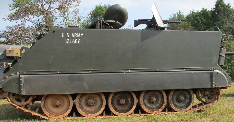
This M113 has been modified to armored cavalry assault vehicle (ACAV) standard. Originally conceived by the Army of the Republic of Vietnam, ACAVs had two 7.62mm machine guns on either side of the cargo hatch in addition to the .50cal MG at the commander's station, and these vehicles were used as light tanks instead of armored personnel carriers. Gun shields were provided to protect the gunners from return fire. Four hundred seventy-six standardized armor kits were ordered from FMC Corp., and these were shipped in July 1966 to Vietnam. The machine guns could be replaced by 40mm grenade launchers or recoilless rifles. Note the height of the idler wheel compared to the road wheels on this early machine.
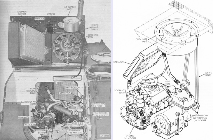
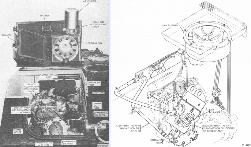
The power plant compartment access door and grille have been opened on the left, and the cooling system is sketched on the right. (Picture from TM 9-2300-224-10.)
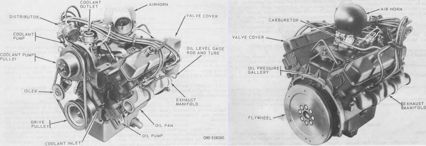
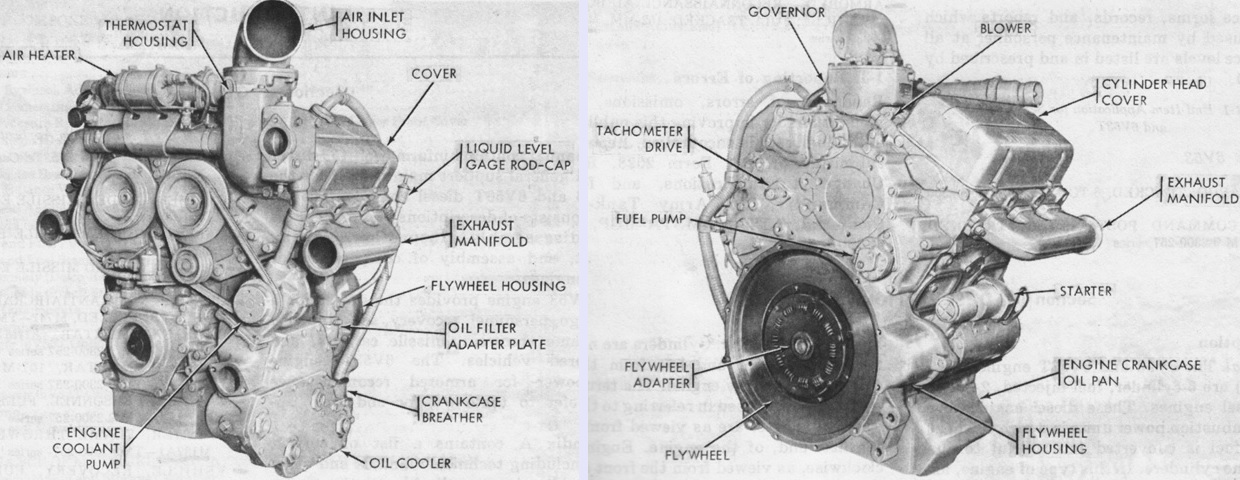
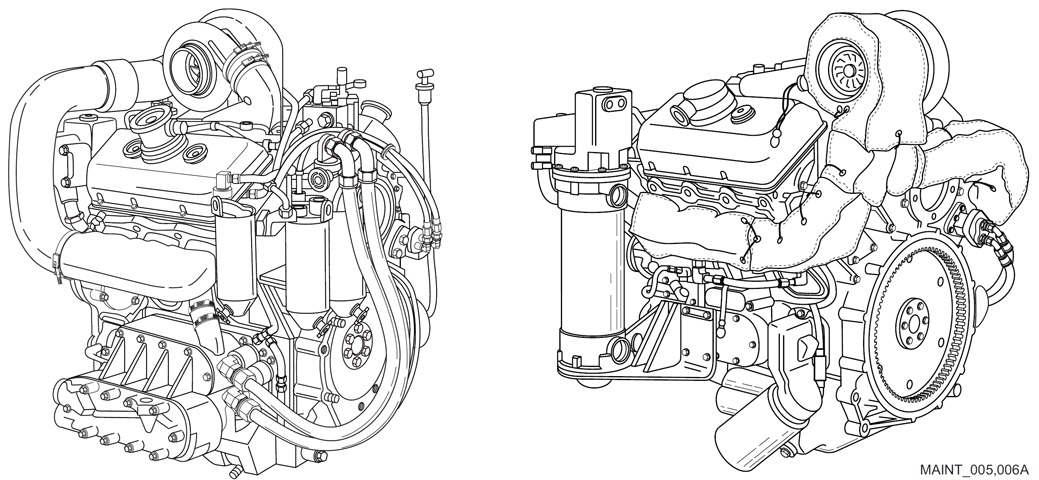
Chrysler's Model 75M engine is shown here from the left front and right rear. The front of the engine was considered the crankshaft pulley end, and the rear the flywheel end. The right and left sides were determined by looking at the engine from the flywheel end. It was a 90° vee, valve-in-head type. Length, width, and height were 34.30" (87.12cm), 25.62" (65.07cm), and 33.25" (84.46cm), respectively. The engine weighed 720lb (330kg) with the carburetor and distributor. Bore and stroke were 4.125" (10.48cm) and 3.375" (8.573cm), respectively, for a displacement of 360.8in³ (5.912L). The compression ratio was 7.8:1. The carburetor was a Holley model 2140SG 4-barrel concentric downdraft type. (Picture from TM 9-2805-216-34.)
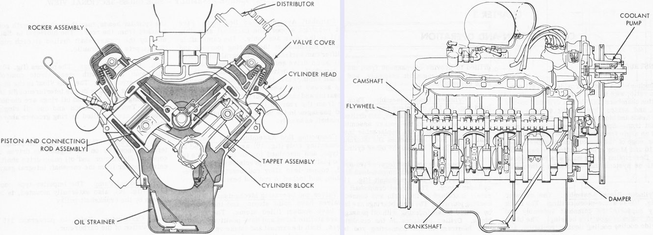
Cross-sections of the 75M are sketched from the rear and side. Each cylinder head and the cylinder block were one-piece castings of chrome alloy cast iron. Valves were in-line, and combustion chambers were wedge-shaped. The left cylinders were numbered 1-3-5-7 front to rear, while the right cylinders were 2-4-6-8. Firing order was 1-8-4-3-6-5-7-2. (Picture from TM 9-2805-216-34.)
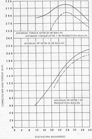
These curves represent the minimum engine performance using automatic spark advance; ignition timing of -10° BTDC at 600rpm; MIL-G-30568 Type I or II fuel; and air induction loss of 3-4 inches of water (750-1,000Pa) at 4,000rpm. (Picture from TM 9-2805-216-34.)
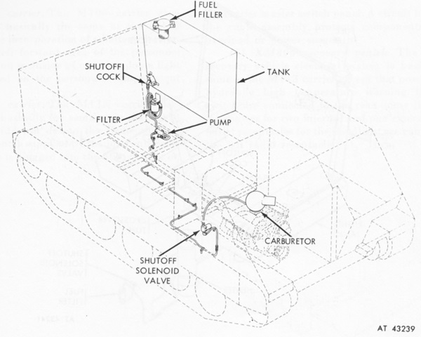
The fuel system with its single storage tank is diagrammed in this image. (Picture from TM 9-2300-224-10.)
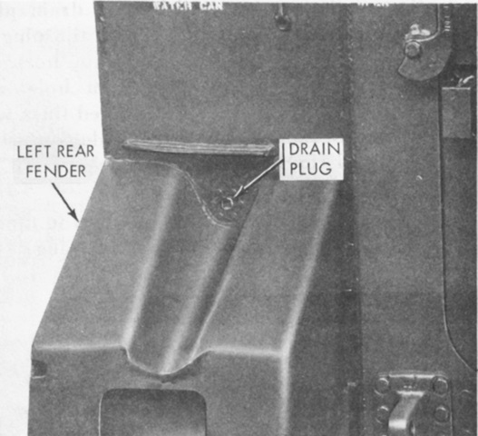
The drain plug for the fuel tank was above the left rear fender, which had a channel formed into its top for this purpose. (Picture from TM 9-2300-224-10.)
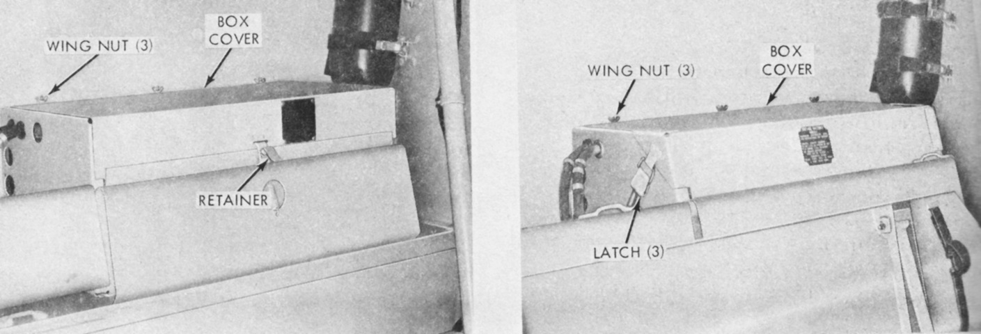
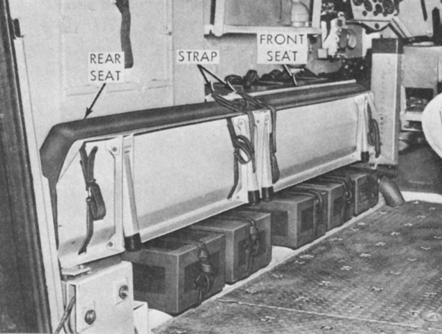
Two 12-volt batteries were connected in series for the 24-volt electrical system, and the battery box could be found at the right rear corner of the passenger compartment. On vehicles serial number F4 through F1283, a retainer attached to the seat backrest by a spring would fit into a slot in the battery box cover to hold it closed, as in the left image. On vehicles F1284 through F3084, two latches on the front of the box cover engaged two rings on the seat backrest to secure the cover. On vehicles after F3084, a latch on each side of the box cover engaged rings on the front corners of the cover to secure it, shown in the right image. (Picture from TM 9-2300-224-10.)
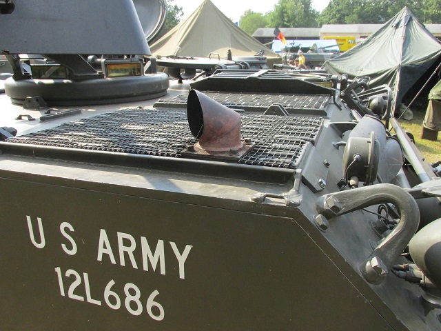
The engine exhaust pipe is seen rising out of the exhaust grille. The air intake grille can be seen inboard of the exhaust grille. A lifting eye is bolted to the front slope. Below the lifting eye is the right headlight cluster; inboard of the lifting eye is the horn and stowage for a shovel.
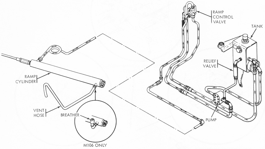
The rear ramp was connected by a steel cable to the hydraulic cylinder hidden under the rear personnel compartment floor plate. The pump was located on and driven by the transfer gearcase, and the system contained 2 quarts (1.9L) of fluid. (Picture from TM 9-2300-224-10.)
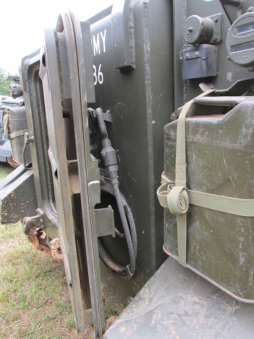
An entry door was provided in the rear ramp, and it is open on this vehicle. A water can is stowed on the right rear fender, and a tow cable is wound on the rear ramp. The right hand taillight can be seen above the water can, and inboard of this is a telephone connector.
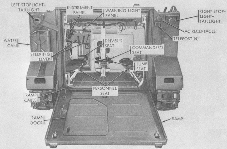
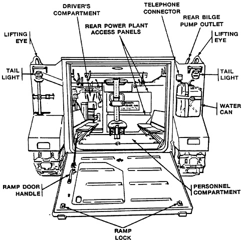
A view of the interior with the ramp lowered is given here. (Picture from TM 9-2300-224-10.)
This view is through the open ramp door. Troops were provided with a two-part bench on each side of the hull, and a rear-facing jump seat was attached to the post for the commander's seat in the center of the compartment. The large roof hatch is distinct with its darker paint. Radio stowage is visible on the left behind the driver.
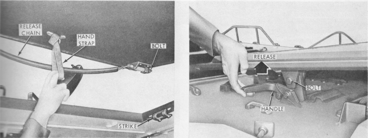
The roof cargo hatch was secured from the inside via two spring-loaded bolts that engaged strikes on each side of the hatch. The bolts were retracted by pulling down on the rubber-covered release chain that was attached to both bolts. The hatch was held in the open position via a hold-open latch on the hull roof. The latch was sprung and engaged a bolt in a bracket on the hatch's left rear. A lift handle was provided to release the latch. (Picture from TM 9-2300-224-10.)
The personnel benches could be stowed to provide more floorspace. (Picture from TM 9-2300-224-10.)
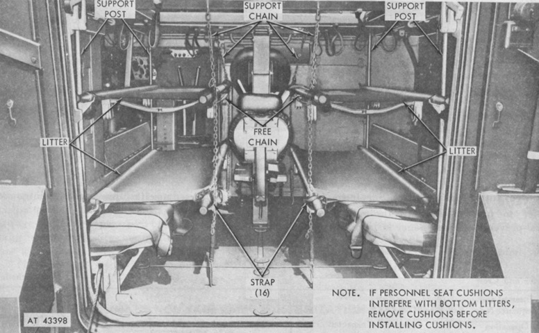
A kit supporting four litters could be installed in the passenger compartment. (Picture from TM 9-2300-224-10.)
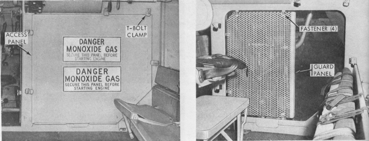
Access to the power plant compartment was provided to the interior of the vehicle via two panels, one on the rear of the power plant compartment and one on its left (i.e., to the driver's right). The rear panel is shown here installed in the left image and removed in the right image. Behind the rear panel was an expanded metal screen that served as a fan belt guard when the panel was removed. The guard could be swung out of the way when its fasteners were released. (Picture from TM 9-2300-224-10.)
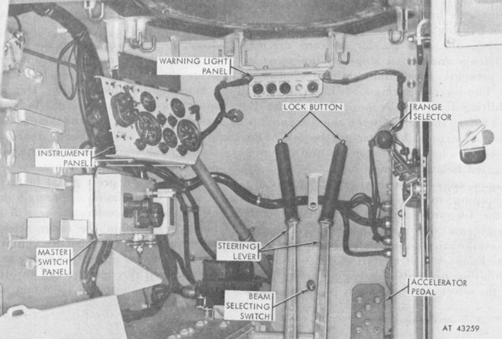
The driver's position is illustrated in this picture. The flat ramp actuation lever is pointing downward below the range selector. It was rotated towards the front of the carrier to lower the ramp, and to the rear to raise it. (Picture from TM 9-2300-224-10.)
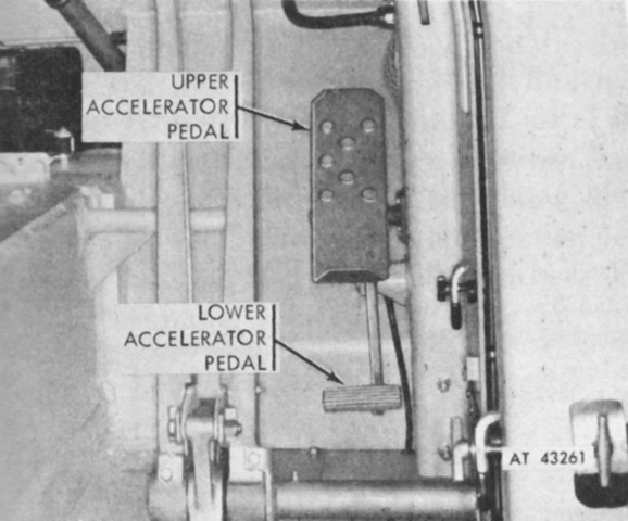
The driver was provided with an upper and lower accelerator pedal. The upper was used when the driver's seat was raised with the hatch open. Conversely, the lower pedal was intended to be used when the seat was lowered with the hatch closed. (Picture from TM 9-2300-224-10.)
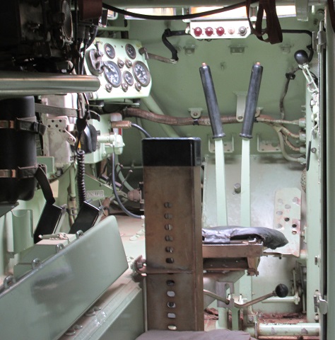
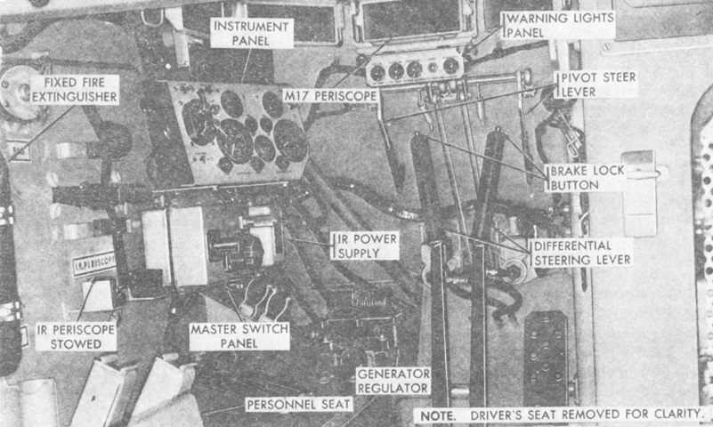
The driver's position in a real vehicle is shown here.
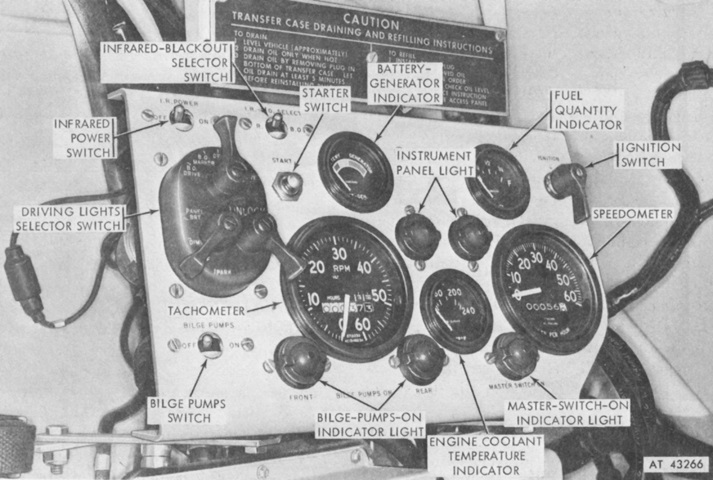
A closeup of the driver's instrument panel is labeled in this picture. (Picture from TM 9-2300-224-10.)
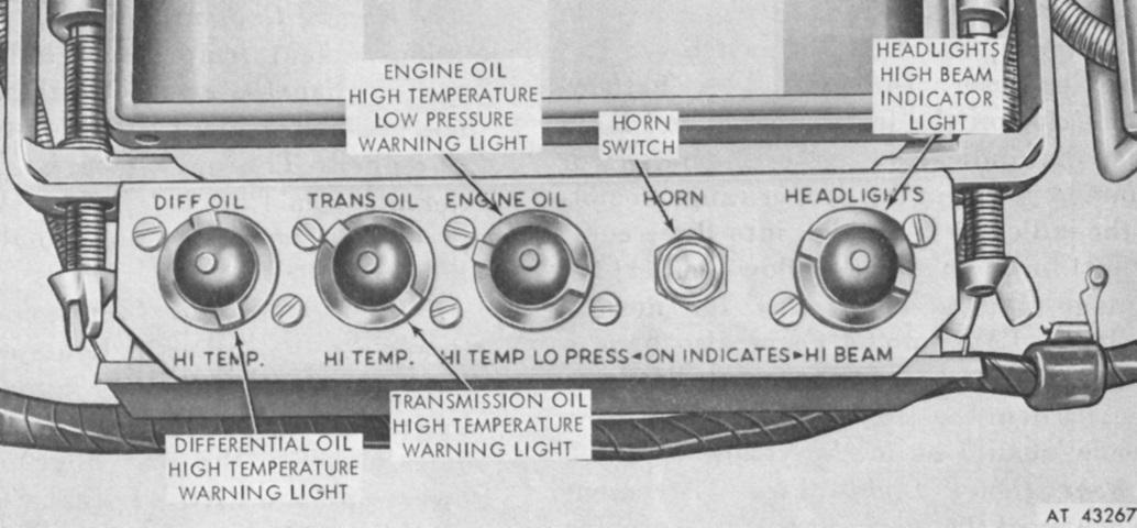
This is a closeup of the driver's warning lamps. (Picture from TM 9-2300-224-10.)
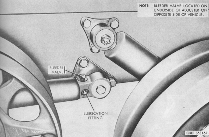
The idler wheel is on the left, with the rear road wheel and its shock absorber visible on the right. To adjust track tension, so that the tracks rested on the third road wheel but remained at least ¼" (.64cm) above the second road wheel after the vehicle coasted to a stop on a firm level surface, GAA grease was added to the track adjuster via the lubrication fitting or removed from the track adjuster via the bleeder valve. (Picture from TM 9-2300-224-10.)
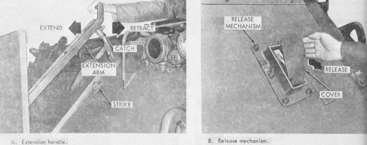
The trim vane on the front of the hull was deployed manually by the driver by pushing on the extension handle until the spring-loaded catch snapped over the strike. The trim vane was retracted by releasing the catch from the strike and pulling the handle until it locked into position. In order to access the engine power plant door on the hull front, the trim vane could be released from the extension arm by a mechanism on the vane's lower left side. (Picture from TM 9-2300-224-10.)
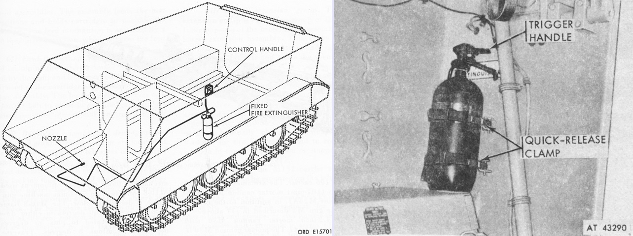
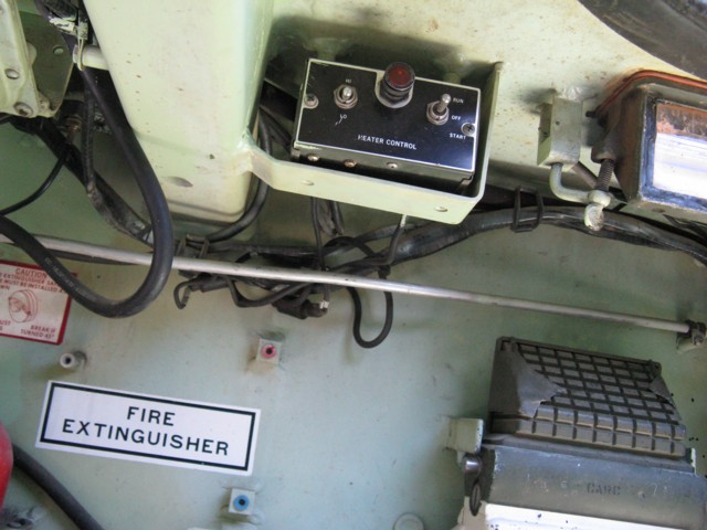
A 5lb (2.3kg) fixed CO2fire extinguisher (left) was mounted on the left side of the hull behind the driver and was used to combat fires in the engine compartment. Actuation handles were located on the extinguisher head and on the top deck behind the driver's hatch. In addition, a 5lb (2.3kg) CO2 portable extinguisher (right) was stowed at the right rear of the passenger compartment. (Picture from TM 9-2300-224-10.)
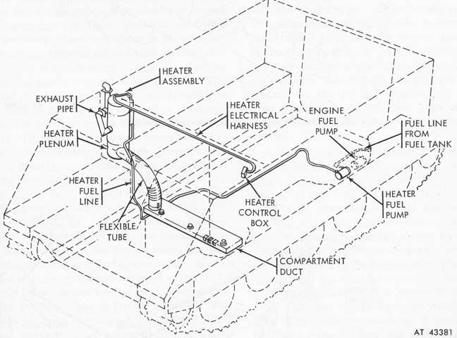
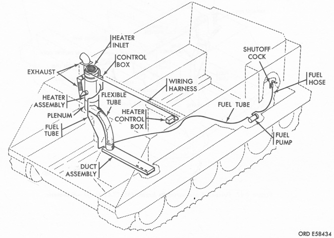
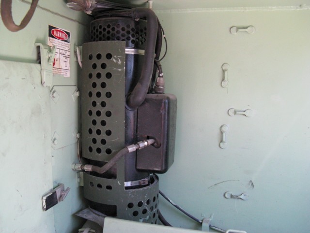
A Stewart-Warner South Wind 1060-D24 or a Hupp Corp. Perfection 510-24-A gasoline-fueled personnel heater was installed at the right front of the passenger compartment. Nominal heat output for each was 60,000BTU at high heat and 30,000BTU at low heat. The heater was plumbed into the carrier's fuel tank, and gasoline consumption was 0.8 gallons/hour (3.0L/hour) at high heat and 0.4 gallons/hour (1.5L/hour) at low heat. (Picture from TM 9-2300-224-10.)
Visually, there was very little external difference between the M113 and M113A1.
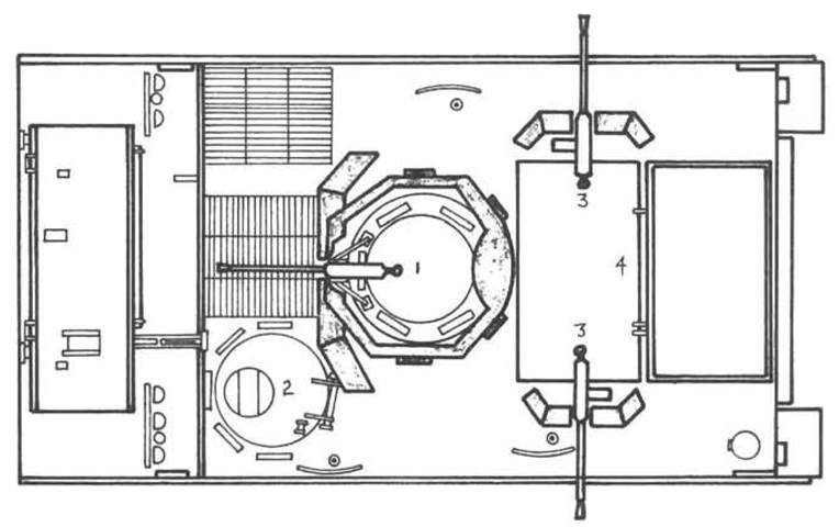
The typical arrangement of weapons and crew of an ACAV is seen from above. 1. Vehicle commander with .50 caliber machine gun. 2. Driver. 3. M60 machinegunners [sic]. 4. M79 [single-shot, shoulder-fired 40mm grenade launcher] grenadier. (Picture from Mechanized and Armor Combat Operations in Vietnam.)
The driver's compartment remained much the same save the addition of the two pivot steer levers, which locked the brake for their respective track and were used during water operations, for short-radius turns, and for emergency stops. The pivot steer levers were to be used with the transmission shift lever in the 1-2 range, and they were not to be used at speeds over 15mph (24kph). When the pivot steer levers were used, the minimum turning radius was 12.8' (3.9m). (Picture from TM 9-2300-257-10.)
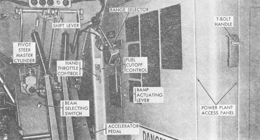
The right side of the driver's compartment is shown here. (Picture from TM 9-2300-257-10.)
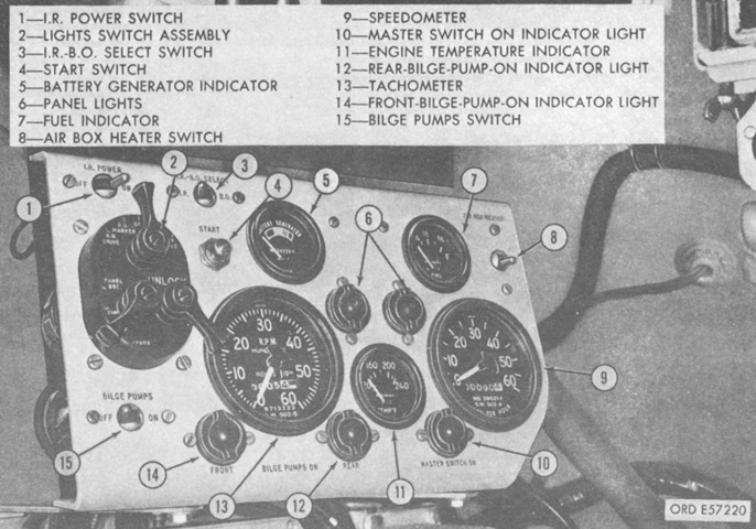
The instrument panel was largely similar, but an air box heater switch was added in place of the ignition switch. This switch was sprung to the off position, and when starting the carrier in temperatures of 40°F to -25°F (4°C to -32°C), the airbox heater switch was to be activated for a second or two immediately before pressing the start switch. (Picture from TM 9-2300-257-10.)
The new 6V53 Model 5063-5299 diesel engine and transmission are shown in the open engine compartment on the left, while the cooling system is drawn on the right. (Picture from TM 9-2300-257-10.)
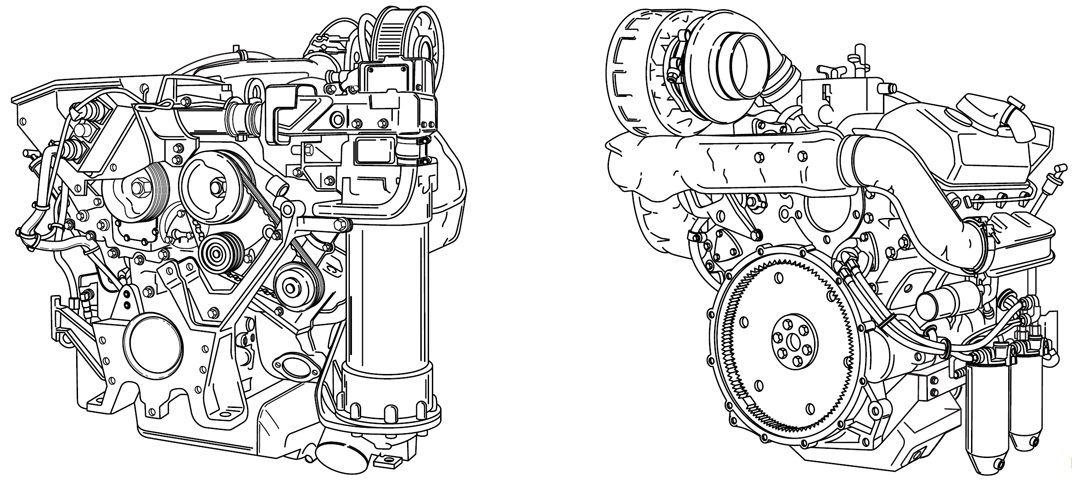
The engine is seen from the left front on the left and the right rear on the right. The accessory end of the engine was considered the front, and the right and left sides were determined by looking at the rear, or flywheel end, of the engine. The cylinders were numbered 1-3 on each side from the front. Firing order was 1L-3R-3L-2R-2L-1R. (Picture from TM 9-2815-205-34 C2.)
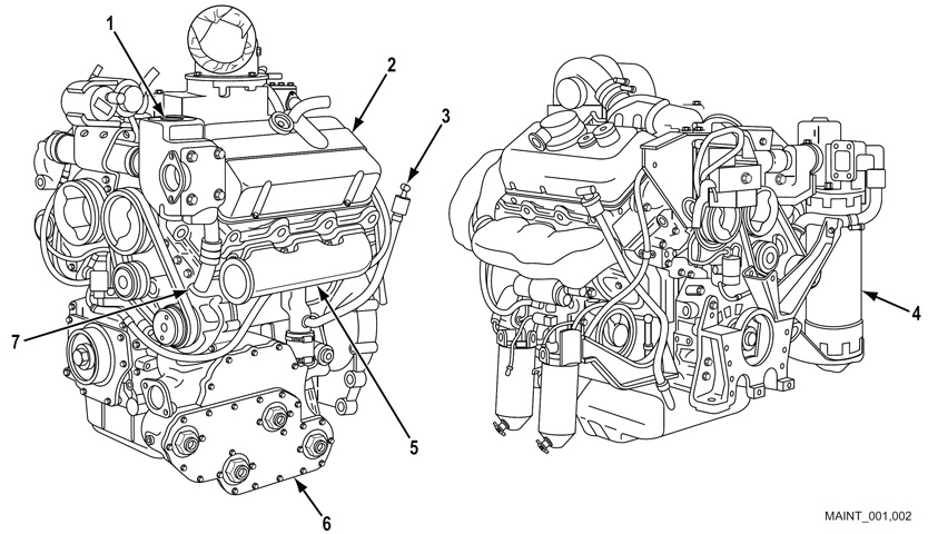
Two further views of the engine are sketched. The 6V53 Model 5063-5299 used trunk pistons, M50 or N50 fuel injectors, a 3-element oil cooler, stamped steel rocker covers, and an airbox heater. Bore and stroke were 3.875" (9.843cm) and 4.5" (11cm), respectively, for a displacement of 318in³ (5.21L). The engine was 32.0" (81.3cm) long, 35.0" (88.9cm) wide, 44.4" (113cm) tall, weighed 1,335lb (605.6kg), and had a 21:1 compression ratio. 1. Thermostat and housing assembly. 2. Valve rocker covers. 3. Oil level gauge rod. 4. Transmission oil cooler. 5. Exhaust manifolds. 6. Engine oil cooler. 7. Water pump. (Picture from TM 9-2815-205-24.)
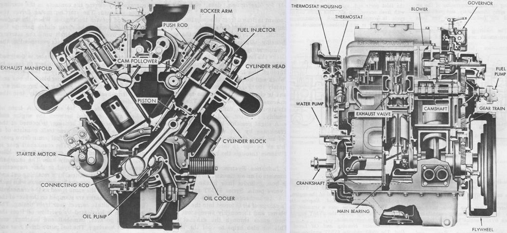
Cross-sectional end and side views of the 6V53 are drawn here. The blower was gear-driven from the crankshaft and forced air into the cylinders via eighteen ports in each cylinder liner, thereby helping expel exhaust gases and supply fresh air for combustion. The engine held 22 quarts (21L) of oil, and the cooling system used 8½ gallons (32L) of coolant. (Picture from TM 9-2815-205-34 C2.)
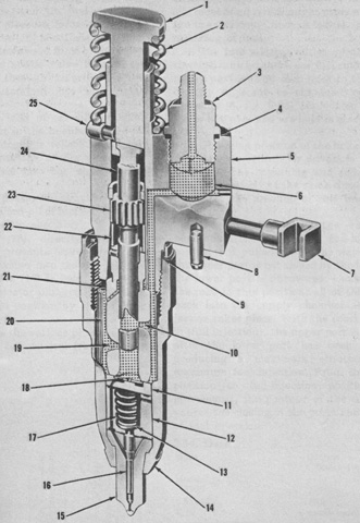
A cross-section of an M50 fuel injector is drawn above. 1. Follower. 2. Follower spring. 3. Filter cap (2). 4. Gasket. 5. Fuel injector body. 6. Filter element (2). 7. Control rack. 8. Dowel. 9. Seal. 10. Upper port. 11. Check valve cage. 12. Spring cage. 13. Spring seat. 14. Nut. 15. Spray tip. 16. Needle valve. 17. Valve spring. 18. Check valve. 19. Lower port. 20. Spill deflector. 21. Plunger bushing. 22. Gear retainer. 23. Gear. 24. Plunger. 25. Stop pin. (Picture from TM 9-2815-205-34 C2.)
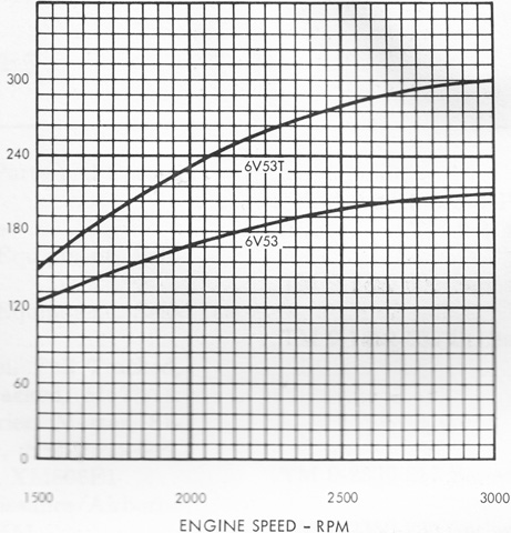
The horsepower performance curve for the 6V53 is drawn, alongside that for the turbocharged 5063-5398 or 5063-5395 6V53T found in the M551 Sheridan. (Picture from TM 9-2815-205-34 C2.)
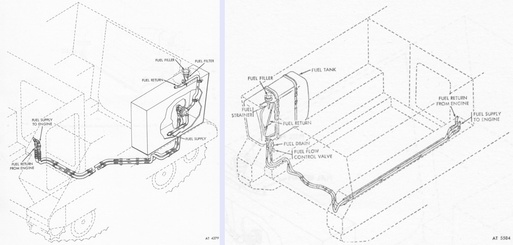
One of two types fuel tanks could be present: the welded-in type is shown in the left schematic, while one secured to the left sponson via two metal straps is shown on the right. (Picture from TM 9-2300-257-10.)
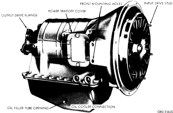
The TX-100-1 was a full powershift, torque converter, planetary gear transmission through which power flowed in a straight line from front to rear through the torque converter, turbine shaft, and transmission output shaft. The torque converter had an automatic lockup clutch that gave direct drive from the engine to the range gearing at higher engine speeds; i.e., the transmission input and output speeds became equal. It had a dry weight of 309lb (140kg), was 17.76" (45.11cm) wide overall, 21.42" (54.41cm) tall overall, and 25.38" (64.47cm) long from the converter housing to the output flange faces. It could handle up to 325lb-ft of input torque and a maximum 4,000rpm input speed. (Picture from TM 9-2520-254-34.)
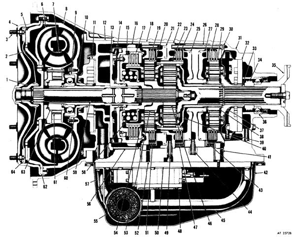
A cross-section of the TX-100-1 is sketched here. 1. Converter pump cover hub. 2. Turbine hub. 3. Converter pump cover drive stud. 4. Converter pump cover assembly. 5. Lockup clutch plate. 6. Converter turbine assembly. 7. Converter stator and cam assembly. 8. Converter pump assembly. 9. Pump hub ball bearing assembly. 10. Converter ground sleeve. 11. Front oil pump. 12. Diaphragm assembly. 13. High-range clutch housing support flange. 14. Front fluid velocity governor. 15. High-range clutch piston. 16. High-range clutch housing assembly. 17. High-range clutch plate. 18. Intermediate-range clutch back plate. 19. Intermediate-range clutch plate. 20. Intermediate-range ring gear. 21. Intermediate-range clutch piston. 22. Intermediate-range clutch piston housing assembly. 23. Low-range ring gear. 24. Low-range clutch plate. 25. Low-range clutch piston. 26. Low- and reverse-range clutch piston housing assembly. 27. Reverse-range clutch piston. 28. Reverse-range clutch plate. 29. Reverse-range ring gear. 30. Reverse-range clutch back plate. 31. Transmission housing. 32. Rear oil pump. 33. Transmission output shaft. 34. Speedometer drive gear. 35. Transmission output flange. 36. Output flange ball bearing. 37. Reverse-range carrier assembly. 38. Reverse-range sun gear. 39. Rear fluid velocity governor. 40. Reverse-range sun gear shaft. 41. Low- and reverse-range clutch anchor pin. 42. Oil pan. 43. Reverse-range clutch return spring. 44. Oil transfer tube. 45. Rear oil pump intake tube. 46. Low-range sun gear. 47. Low-range clutch return spring. 48. Control valve assembly. 49. Oil transfer tube retaining ring. 50. Oil transfer plate. 51. Intermediate-range clutch return spring. 52. Intermediate-range clutch anchor pin. 53. Intermediate-range sun gear. 54. Intermediate-range carrier assembly. 55. Oil filter. 56. Back plate spacer. 57. Front oil pump intake tube. 58. High-range clutch piston return spring. 59. Converter turbine shaft. 60. Pump hub. 61. Freewheel roller. 62. Lockup clutch back plate. 63. Freewheel roller race. 64. Lockup clutch piston assembly. (Picture from TM 9-2520-254-34.)
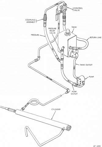
The ramp hydraulic system is sketched here, and continued to hold 2 quarts (1.9L) of fluid. (Picture from TM 9-2300-257-10.)
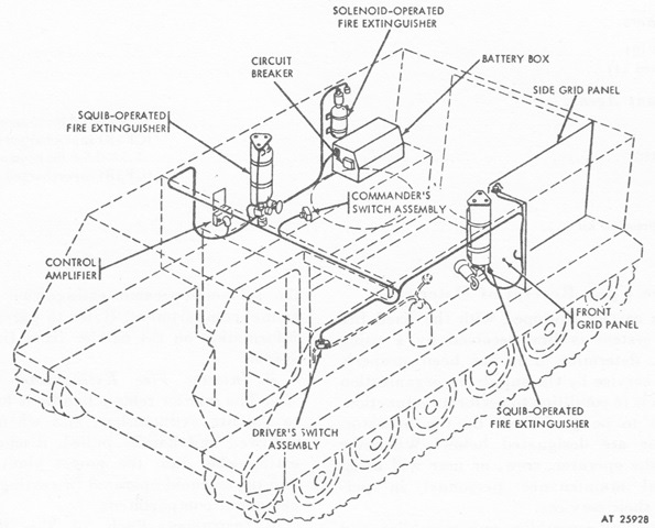
A fixed Freon fire suppression kit was developed to supplement the existing fixed CO2 extinguisher. Two 5lb (2.3kg) CBrF3 cylinders were actuated by explosive squib discharge valves, and a 7.5lb (3.4kg) CBrF3 cylinder was actuated by an electronically operated solenoid valve. The squib-operated cylinders could automatically discharge into the passenger compartment if wire grid detector panels mounted on the fuel tank were ruptured or penetrated, if the ambient temperature exceeded 212°F (100°C), or if the internal pressure of a cylinder exceeded 2,400psi (170kg/cm²). Manual electrical switches for the solenoid of the third cylinder, which also discharged into the passenger compartment, were placed at the driver's instrument panel and on the top deck near the commander's cupola. Additionally, if the CO2 extinguisher was activated, a pressure switch in that discharge line would trigger the solenoid valve of the third cylinder. The third cylinder would also discharge if its internal pressure exceeded 1,000psi (70kg/cm²). The entire kit weighed 237lb (108kg), and was not compatible with the litter kit. (Picture from TM 9-2300-257-10.)
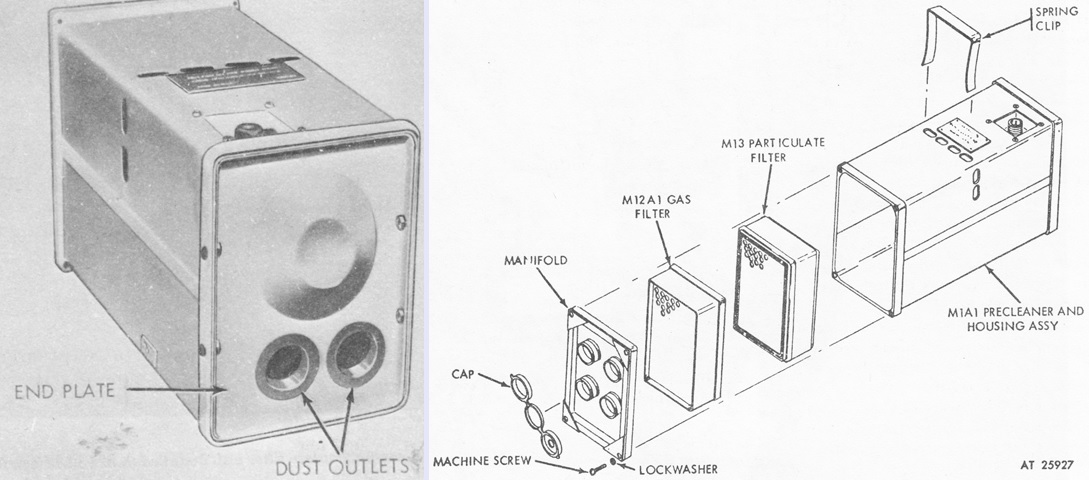
An M8A3 gas-particulate filter unit could be mounted to protect personnel from toxic gases, biological agent attack, and extremely dusty air. The unit did not protect against carbon monoxide, however. The unit consisted of an air purifier M2A2 connected via hose assemblies to M14A1 tank gas masks. A bottom view and an exploded diagram of the air purifier are provided in the left and right images above, respectively. The purifier was composed of a steel housing containing a particulate filter M13, gas filter M12A1, and air purifier precleaner M1A1. Four sockets for hose connection were provided in the outlet end; if less than four hoses were used, caps were to seal the unused sockets. (Picture from TM 9-2300-257-10.)
The personnel heater was usually a Stewart-Warner 9460C24, but a Perfection MF510 heater was optional. These were multifuel-burning heaters that remained plumbed into the carrier's fuel system. Heat output was identical to the gasoline-fueled heaters found in the M113. (Picture from TM 9-2300-257-10.)
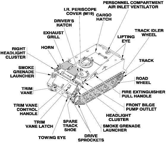
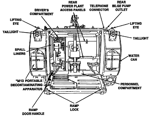
External features are labeled in this diagram. (Picture from TM 9-2350-261-10.)
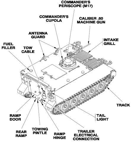
The rear of the vehicle is shown here. (Picture from TM 9-2350-261-10.)
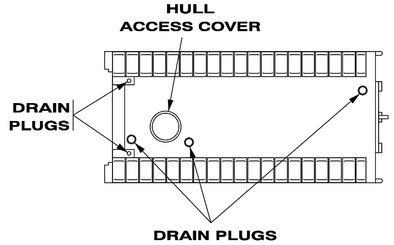
There were five drain plugs and a larger access hatch on the underside of the hull. (Picture from TM 9-2350-261-10.)
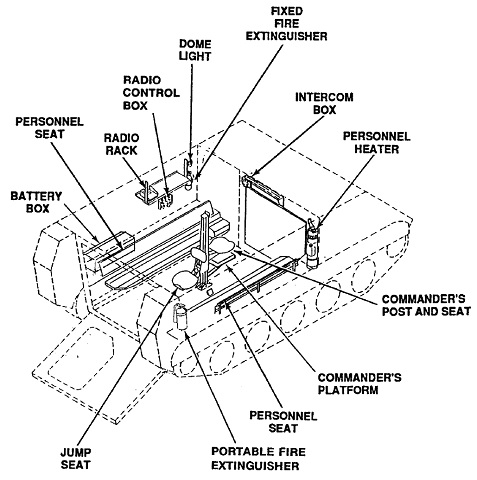
A look into the personnel compartment is provided in this sketch. (Picture from TM 9-2350-261-10.)
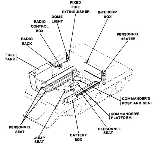
This ghosted image shows the location of the fuel tank and batteries. (Picture from TM 9-2350-261-10.)
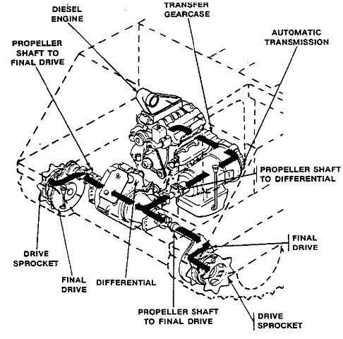
The drivetrain is diagrammed in this picture. (Picture from TM 9-2350-261-10.)
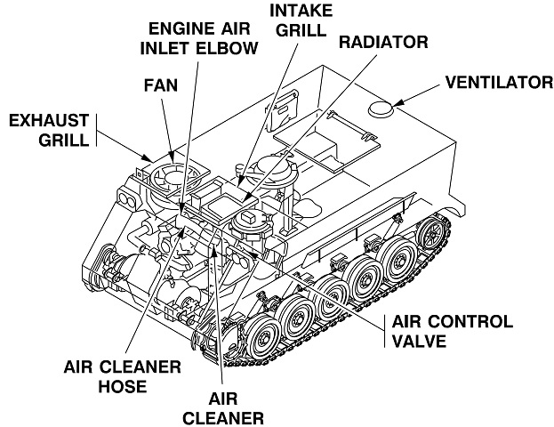
The cooling system is diagrammed in this picture. Note the locations of the fan and radiator compared to earlier machines, as seen above. (Picture from TM 9-2350-261-10.)
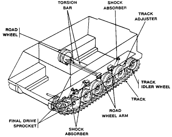
The suspension layout is illustrated here. (Picture from TM 9-2350-261-10.)
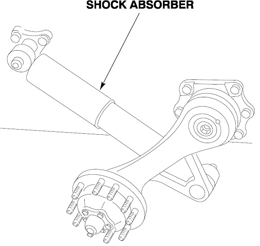
The orientation and mounting of a shock absorber and road wheel arm are shown here. (Picture from TM 9-2350-261-10.)
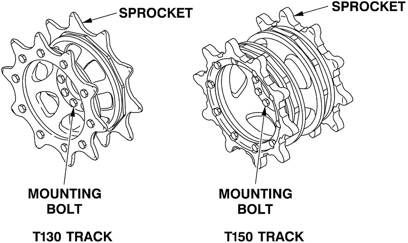
Differences in the drive sprockets for the two different tracks can be gleaned from this drawing. (Picture from TM 9-2350-261-10.)
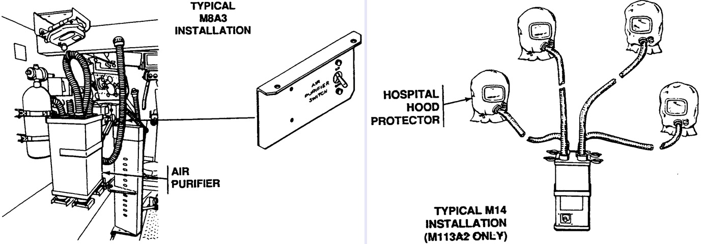
A typical installation of the M8A3 NBC system is shown on the left. The M13 NBC system added heaters to heat the purified air in cold weather, and the M14 NBC system added hospital hood protectors for disabled patients (right). (Picture from TM 9-2350-261-10.)
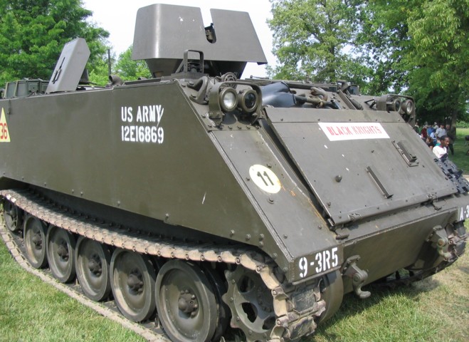
This M113A2 has been outfitted to look like a Vietnam-era ACAV vehicle, but its raised idler wheel and revised engine exhaust outlet give it away. Smoke grenade launchers are not fitted to this vehicle.
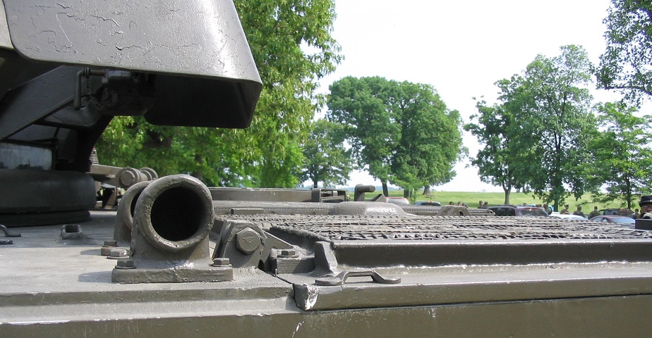
These two pipes are for the personnel heater. The exhaust elbow is in the foreground, and the intake elbow is partially hidden behind it.
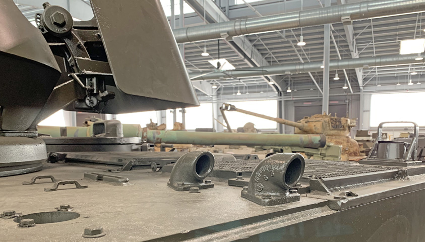
A better view of the spatial relationship of the personnel heater elbows is provided here, and the main engine exhaust is visible at the right. An opening for a radio antenna is in the roof to the rear of the personnel heater elbows.
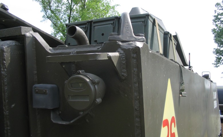
At the left rear corner of the hull is the rear bilge pump outlet. A lifting eye is just to the right of the pump outlet, and below these are the right tail light and the telephone connector.
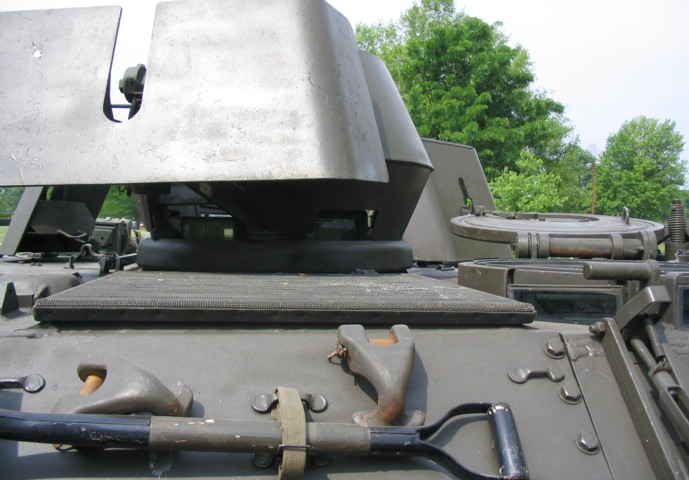
The driver's position can be seen to the right of this image, and the vehicle commander was placed directly ahead of the camera. The mesh grille just to the driver's right is for engine air intake. An exhaust grille was placed to the right of the air intake grille. Tow hooks can be seen stowed above the shovel.
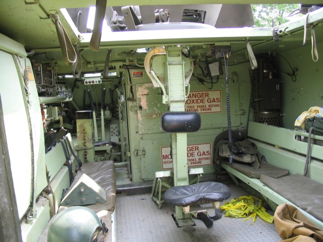
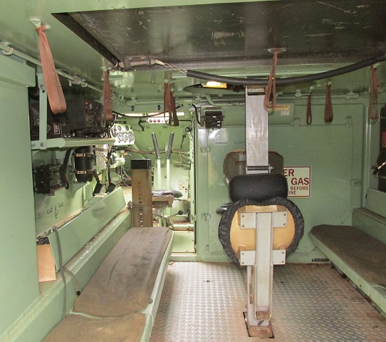
As above, two bench seats for passengers are placed along the hull sides, and a single jump seat is directly behind the vehicle commander's position. The roof hatch is open on this vehicle. The dark green device in the front right corner of the passenger compartment is the personnel heater.
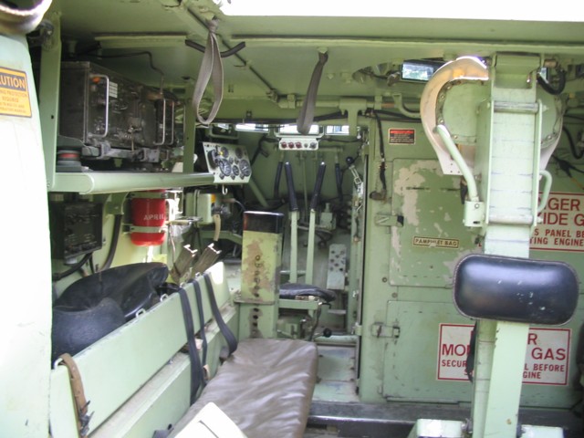
A closer look at the interior is provided here. The radio and intercom installation is on the left side of the vehicle, and just ahead of this is a fire extinguisher bottle. The driver's adjustable seat post is at the front of the vehicle, and the steering levers, instruments, and accelerator pedal are all visible. The black-knobbed lever placed high to the driver's right is the transmission shift lever, and just below this is the ramp actuating lever.
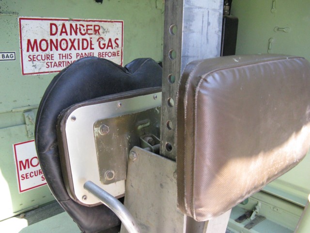
The vehicle commander's seat here is folded up in front of the post in the middle of the fighting compartment. The seat back for the single jump seat is attached to the opposite side of the post. The height adjustment for the commander's seat is obvious.
A closer view of the personnel heater is provided here. The large attachments to the left of the image hold the rear power plant access panels.
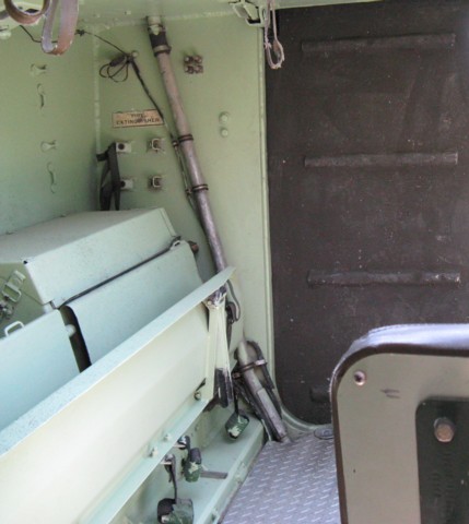
The right side of the passenger compartment is shown in this image. The rear ramp is painted darker than the rest of the interior, and the right side bench seat is folded up. The tube climbing the rear wall is the rear bilge pump outlet.
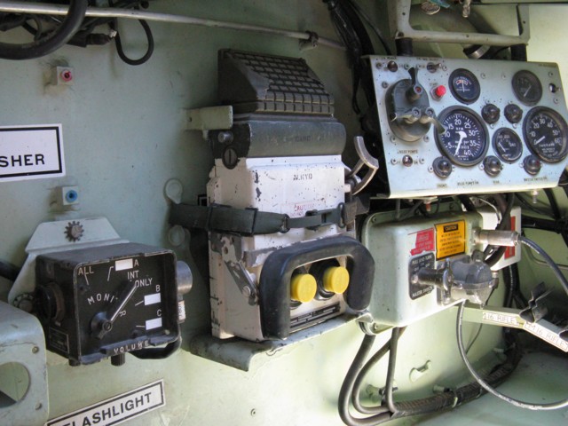
The left side of the driver's position is shown here. The green intercom control box is mounted behind the stowage spot for the driver's infrared periscope M19. The master electrical box is below the driver's instrument panel. The rearmost switch on this box is the master switch, and the larger gray auxiliary power receptacle is just to the front of the master switch. The IR power supply is in front of the electrical box.
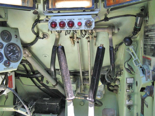
From left to right, the warning lights on the driver's warning light panel are for high differential oil temperature, high transmission oil temperature, and high engine oil temperature. To the right on this panel are buttons for the horn and headlights. Three of the four M17 periscopes that ring the driver's hatch can be seen to the top of the image. The transmission control lever is on the right wall, and below this is the ramp actuation lever. From top to bottom, the three handles to the driver's right front are for fuel cutoff, throttle control, and air vent control. The headlight dimmer switch can be seen between the steering levers, and clips for M16 rifle stowage are mounted in the front left corner. The downward-oriented levers in front of the steering levers are the pivot steer levers. Pulling on one of these would apply the disc brake and thereby lock the track on that side, allowing the vehicle to pivot around that track.
The control box for the personnel heater is mounted on the vehicle's left side, behind the driver.
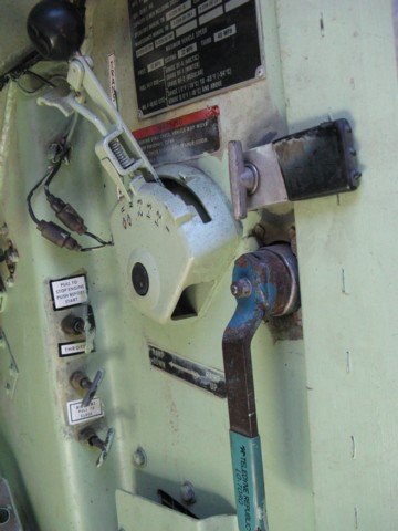
The markings on the transmission shift control lever are for, front to back, reverse, neutral, 2-3 gears, 1-3 gears, 1-2 gears, and first gear. The ramp actuation lever to the bottom would be swung forward to lower the ramp.
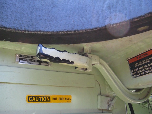
The locks for the rear ramp are controlled by a lever over the driver's right shoulder. The right rear of his hatch is visible to the top of the image, and a power plant compartment access door is marked with a yellow warning sticker.
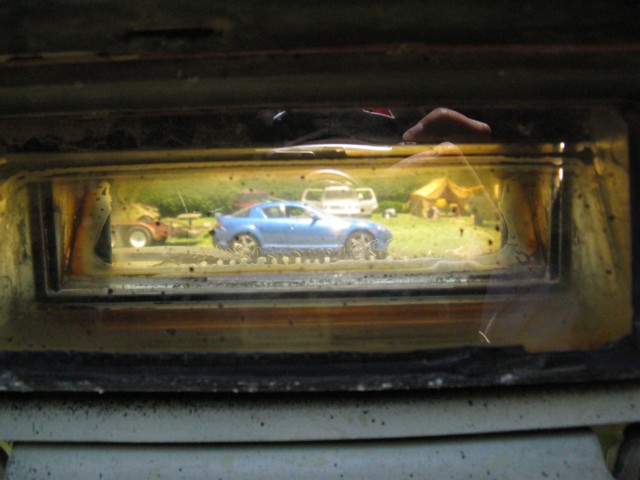
This Mazda RX-8 is seen through the driver's front M17 periscope.
Besides the external fuel tanks and the absence of a trim vane, there's not much externally to visually distinguish an M113A3 from the above M113A2. (Picture from TM 9-2350-277-10.)
The rear of the carrier is shown here. (Picture from TM 9-2350-277-10.)
The 6V53 Model 5063-5393 featured a TV7303 turbocharger mounted on a bracket at the engine's rear, crosshead pistons, 5C55 fuel injectors, a 1-element engine oil cooler, a tube-in-shell transmission oil cooler, die cast aluminum rocker covers, a blower with a bypass valve in the rear endplate, an hydraulic pump drive gear, and an airbox heater. The engine was 39.0" (92.7cm) long, 40.0" (101cm) wide, 42.8" (109cm) tall, weighed 1,745lb (791.5kg), and had an 18:1 compression ratio. (Picture from TM 9-2815-205-24.)
The 6V53 Model 5063-539L was similar to the 5063-5393, but used glow plugs as its starting aid rather than an airbox heater. (Picture from TM 9-2815-205-24.)
This view is looking into the open passenger compartment. The spall liners can be contrasted with the above vehicle. (Picture from TM 9-2350-277-10.)
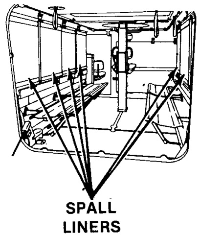
The spall liners are highlighted here. (Picture from TM 9-2350-277-10.)
The relocation of the fuel tanks allowed the interior stowage to be slightly reworked. (Picture from TM 9-2350-277-10.)
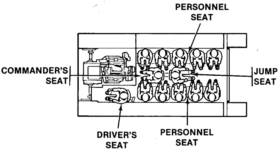
The positions of the crew and passengers are sketched here. (Picture from TM 9-2350-277-10.)
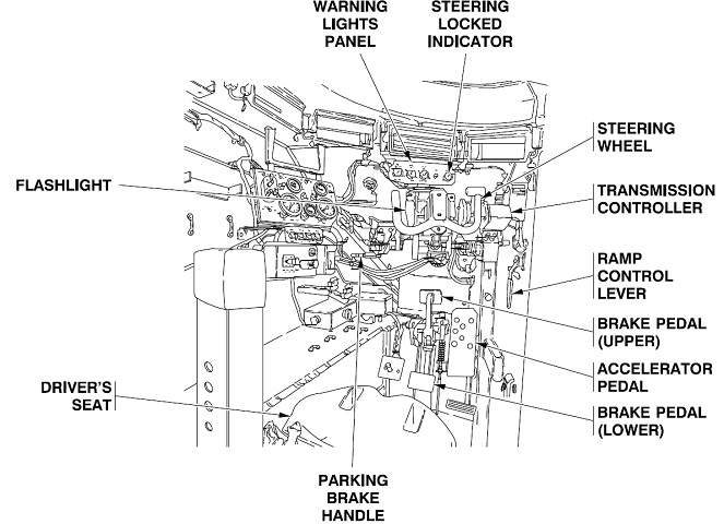
The original driver's station is drawn here. A steering yoke has replaced the earlier steering levers, and stowage was provided near the driver for an AN/VVS-2 night vision periscope. Since with the new transmission the carrier would pivot regardless of the transmission controller position, the steering wheel needed to be centered and locked whenever the vehicle was started, shut down, or idled. The transmission did have a specific pivot (PV) setting. The upper brake pedal was used when the driver's seat was in the raised position. The parking brake handle simply locked the service brakes into position; pressure was applied to the brake pedal, then the parking brake handle was pulled. (Picture from TM 9-2350-277-10.)
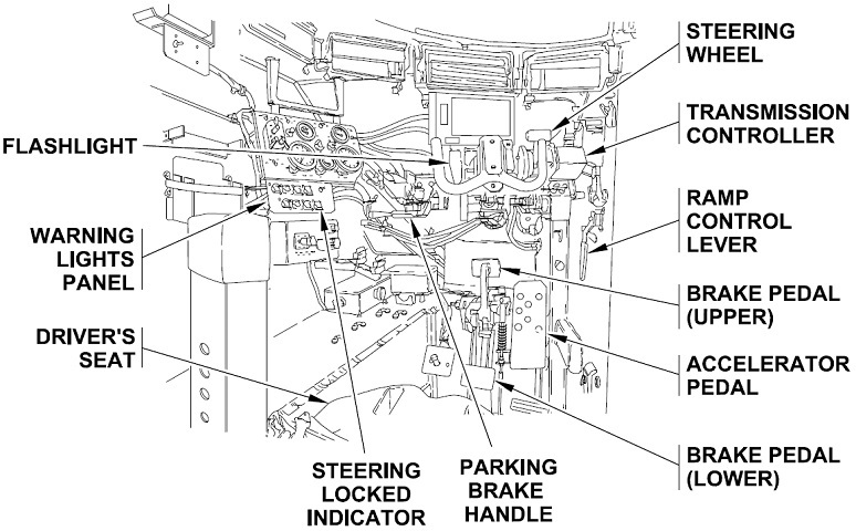
The newer configuration replaced the AN/VVS-2 with the AN/VAS-5 driver's vision enhancer. (Picture from TM 9-2350-277-10.)
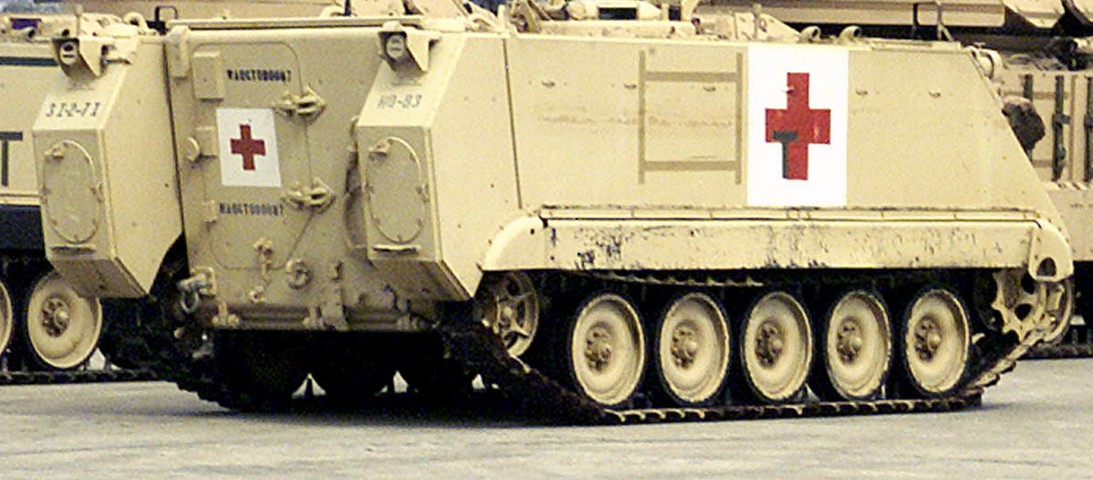
The external fuel tanks are mounted on this M113A3. The door in the left side of the rear ramp can also be seen. This vehicle was awaiting deployment at Hunter Army Airfield. (Picture taken 28 Feb 2001 by Donald Teft; available from the Defense Visual Information Center.)
