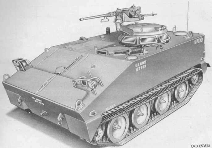
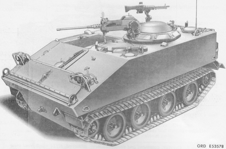
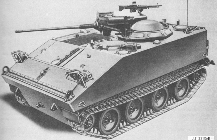
Armored Command and Reconnaissance Carrier M114.
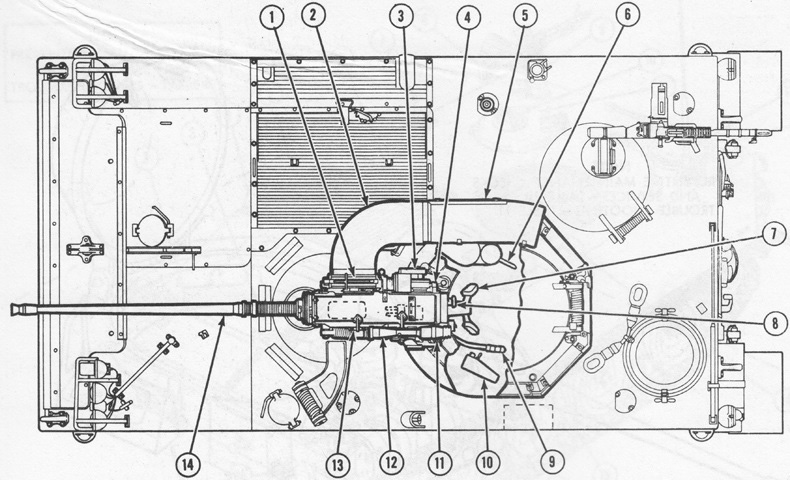
The driver's position in the front left and the commander's cupola can be seen in this overhead view. (Picture from TM 9-2320-224-10 C4.)
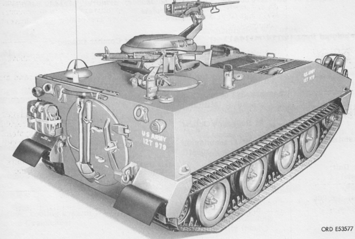
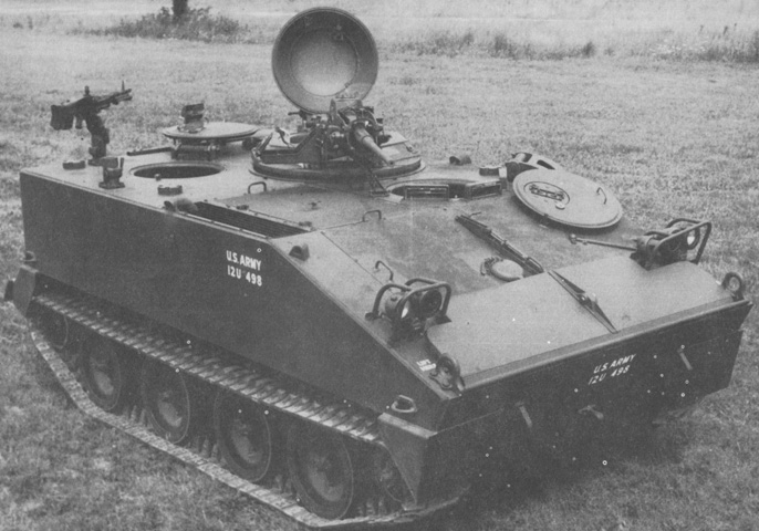
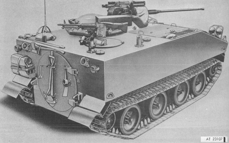
Pioneer tools were stowed on and around the round rear hatch, and the observer had a roof hatch with two mounts for his 7.62mm machine gun. (Picture from TM 9-2320-224-10 C4.)
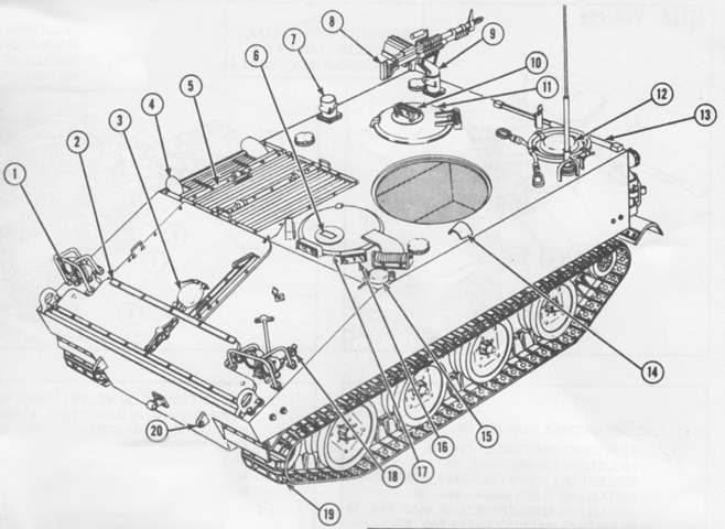
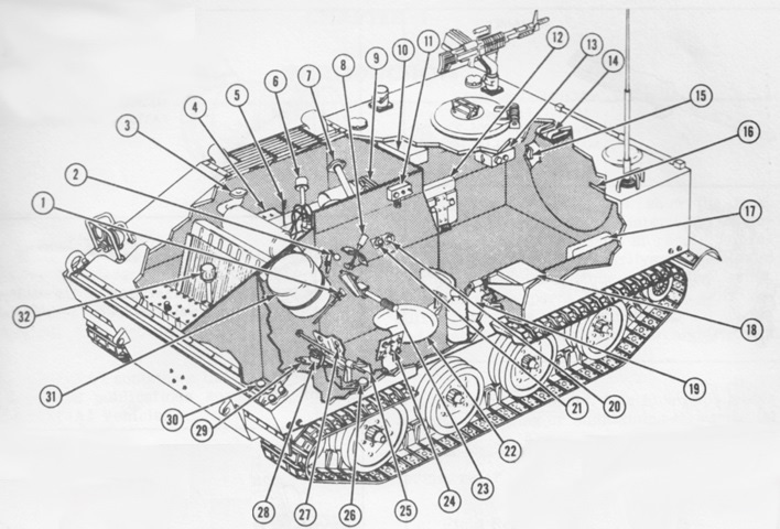
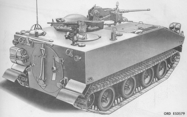
External features are labeled in this drawing. 1. Driving lights. 2. Surfboard. 3. Geared-steer unit oil level access cover. 4. Bilge pump. 5. Air inlet & exhaust grille. 6. M19 (IR) periscope. 7. 7.62-mm machine gun pintle support. 8. 7.62-mm machine gun M60. 9. Gun mount M142. 10. M13 periscope. 11. Observer's hatch cover. 12. Personnel air vent. 13. Basic issue items. 14. Fixed fire extinguisher. 15. Fuel filler cover. 16. M26 periscope. 17. Driver's hatch cover. 18. Power plant master warning light. 19. Suspension. 20. Towing lug. (Picture from TM 9-2320-224-10 C4.)
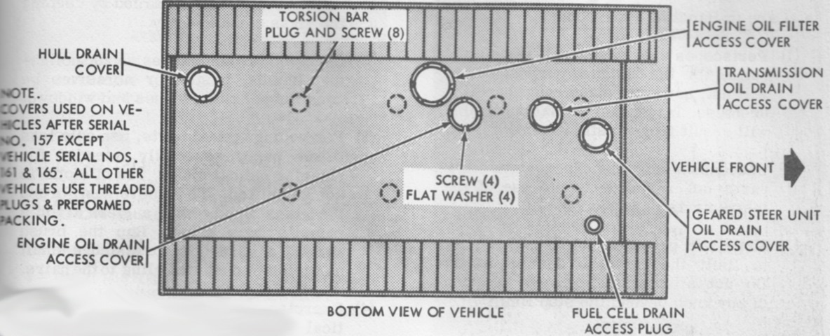
The various plugs and access covers on the hull bottom are illustrated here. (Picture from TM 9-2320-224-10 C4.)
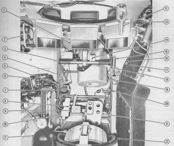
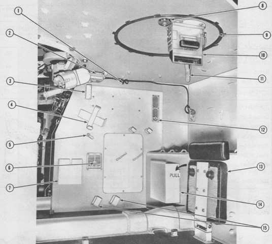
The interior of the vehicle is sketched here. 1. Parking brake lock. 2. Steering selector lever. 3. Radiator coolant surge tank filler cap. 4. Batteries. 5. Engine oil level dipstick. 6. Transmission oil level dipstick and filler tube. 7. Engine oil filler tube. 8. Transmission shift lever. 9. Drive "V" belts. 10. Gas-particulate filter unit. 11. Personnel heater control box. 12. Observer's jump seat. 13. Intercom box. 14. Dome light. 15. Tow, pintle kit and/or trailer lighting receptacle. 16. Hull rear door. 17. Jump seat (passenger). 18. Radio equipment. 19. Portable fire extinguisher. 20. Throttle control knob. 21. Choke control knob. 22. Driver's seat. 23. Steer bar. 24. Driver's switch and indicator panels. 25. Brake pedal. 26. Fuel shut-off valve. 27. Accelerator pedal. 28. Auxiliary power (slave) receptacle. 29. Accessory outlet receptacle. 30. Fuel drain plug. 31. Air cleaner. 32. Geared-steer unit oil level dipstick and filler tube. (Picture from TM 9-2320-224-10 C4.)
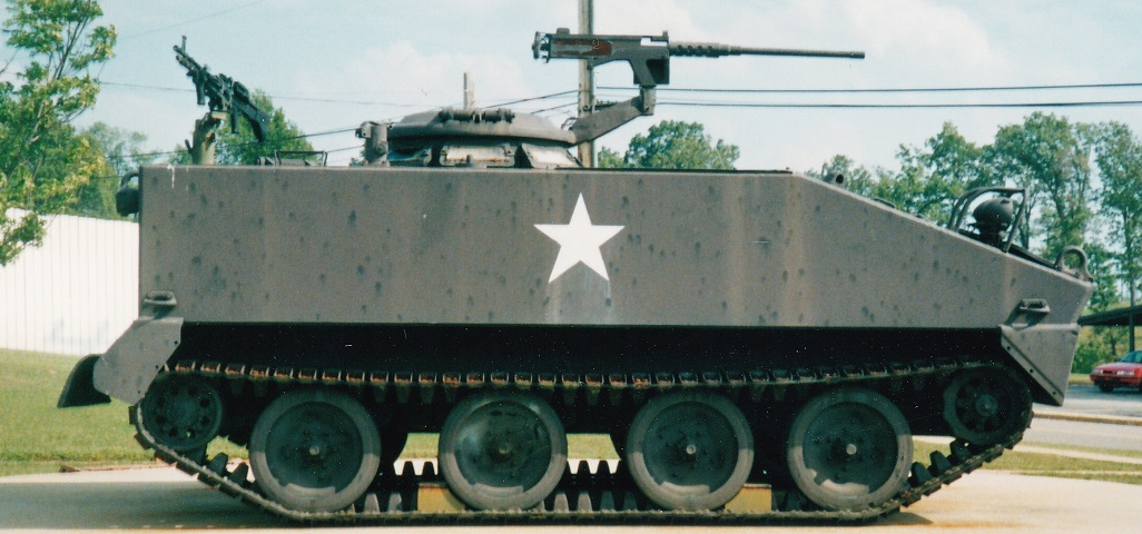
Although amphibious, the small angle of approach and large front overhang served to limit the vehicle's ability to climb out of streams or up steep banks.
The driver's hatch is open, and is visible resting on the front hull plate. The trim vane only reaches halfway up the hull front, and its outline can be seen in front of the headlight guards.
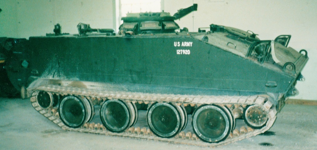
The positioning of the open driver's hatch and trim vane can better be seen on this machine.
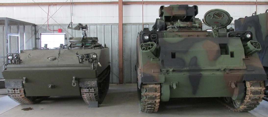
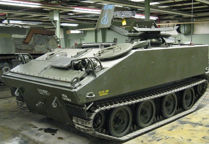
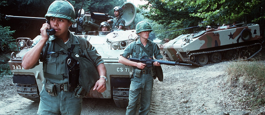
The diminutive size of the M114 is shown well here with it parked next to a relatively hulking fire support team vehicle M981. The surfboard is absent on this M114 .
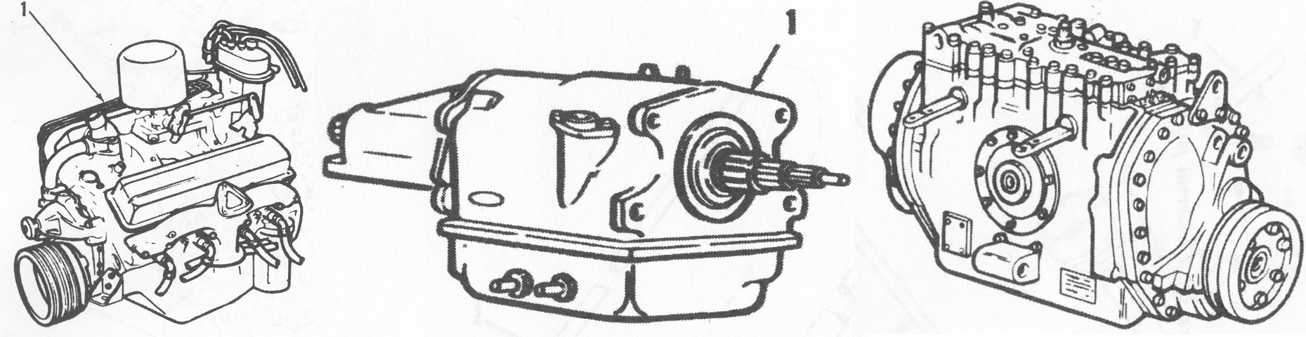
Components of the vehicle's powertrain are sketched here (though not to scale), with the engine, transmission, and steering gear shown from the left to right. (Pictures from TM 9-2350-244-24P.)
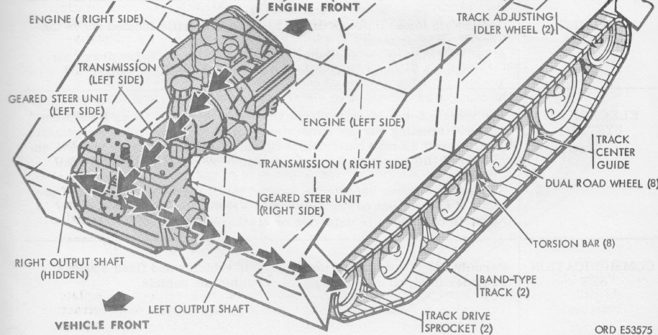
The installed powertrain is diagrammed in this drawing. Note the front/rear orientation of the powertrain versus that of the vehicle hull. (Picture from TM 9-2320-224-10 C4.)
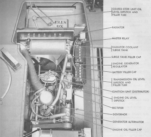
Parts of the installed powerplant are labeled in this image. (Picture from TM 9-2320-224-10 C4.)
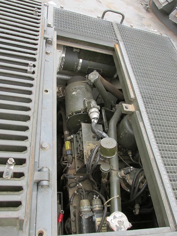
The engine is visible through the open grille in this image.
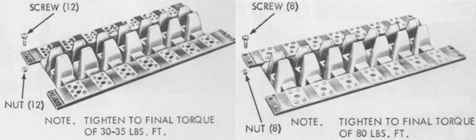
The track was redesigned during production; the old style on the left can be contrasted with the new version on the right. The early track was to be replaced after 1000 miles (1600km) of service. (Picture from TM 9-2320-224-10 C4.)
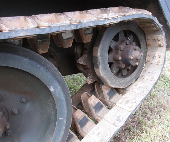
Details of the drive sprocket are shown here. Note the late-type track.
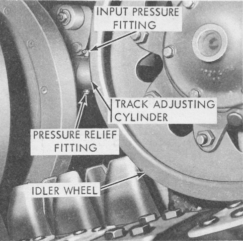
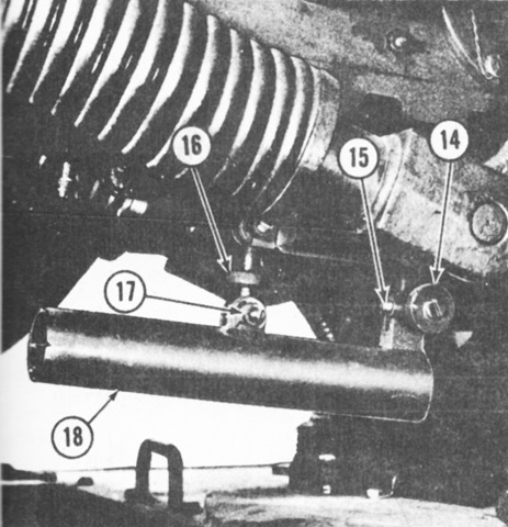
Track tension was adjusted by injecting grease into or releasing grease from the track adjusting cylinder, which would respectively extend or retract the idler wheel. (Picture from TM 9-2320-224-10 C4.)
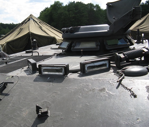
The driver's position is shown here, ringed by his M26 periscopes, and the commander's cupola is directly behind. To the driver's right is the engine air inlet and exhaust grille. The filler cover to the driver's front left is for fuel, and the catch for the driver's hatch when it was open can be seen on the front slope below the forward periscope.
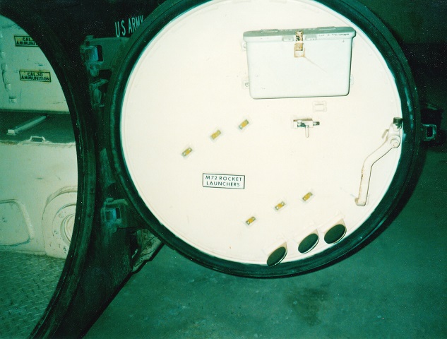
The M114 featured a round rear entry door, and it is open on this vehicle. Visible on the door interior are the mounting points for three M72 light antitank weapons.
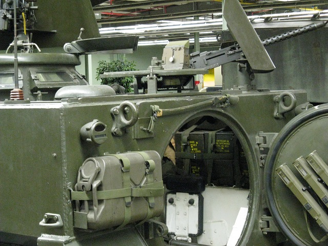
Stowage is in place on this vehicle, including the antitank rockets on the rear door. The observer's and commander's hatches are open, and the periscope in the observer's hatch can be seen. The mushroom-shaped structure on the left rear corner of the roof is an air vent.
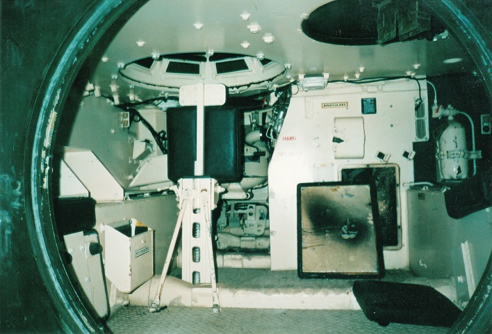
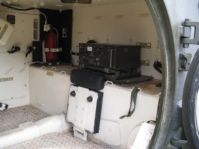
Looking through the open hatch, the stations for the crewmen are visible. The observer was positioned in the right rear of the vehicle; his hatch is obvious in the roof, and his seat faces inward on the floor. The folded passenger jump seat is visible across from the observer's spot. The commander's cupola is in the center of the vehicle's roof, and the driver sat in the front left of the M114. The vehicle's engine compartment is to the driver's right, and a radio would normally be placed on the shelf just to the commander's left. Guards for the suspending torsion bars can be seen running across the floor.
The observer's position is detailed here. His seat is folded up on this vehicle, and a radio is mounted behind him.
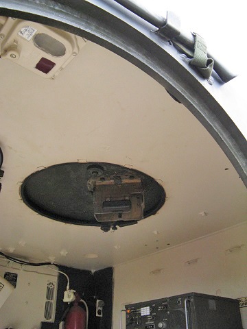
The observer's hatch was provided with a periscope mount, and the location of a dome light can be seen on the roof in the center of the entryway.
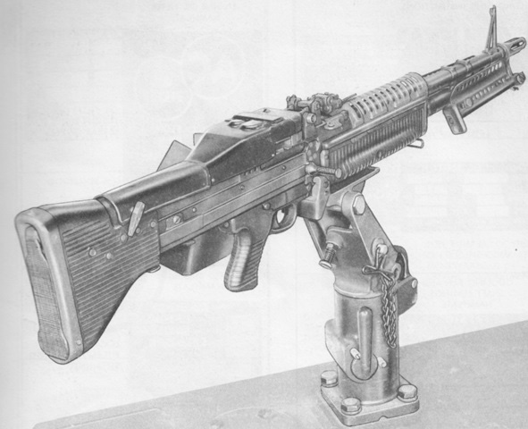
The observer was provided with two places to install the M142 mount for his M60 machine gun, one at the rear and one on the hull roof's right side. (Picture from TM 9-2320-224-10 C4.)
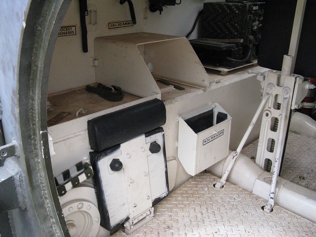
The passenger seat is shown here. The mounting point of the rear idler wheel can be seen immediately to the passenger's right, and the vertical support for the commander's seat overlaps the torsion bar guard on the floor.
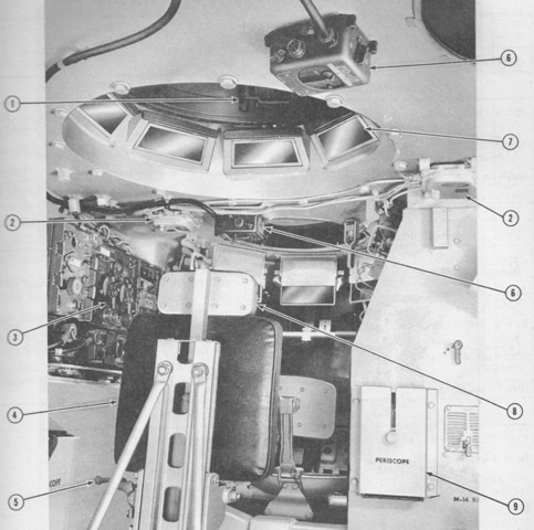
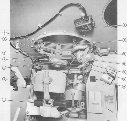
The commander's position is shown here. 1. Hatch cover locking assembly. 2. Dome light. 3. Radio equipment. 4. Commander's seat. 5. Height adjustment handle (pull up and with body weight raise or lower seat). 6. Intercom box. 7. Vision block (8). 8. Commander's seat backrest. 9. M13 spare periscope stowage box. (Picture from TM 9-2320-224-10 C4.)
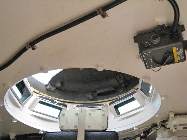
This interior of the commander's cupola is further illustrated in this image.
The driver's position is labeled in this picture. 1. M26 periscope. 2. Indicator panel. 3. Steer bar. 4. Fuel sight tube 5. Accessory outlet receptacle. 6. Driver's switch panel. 7. Auxiliary power receptacle. 8. Fuel shut-off valve. 9. Brake pedal. 10. Foot rest. 11. Fixed fire extinguisher. 12. Driver's hatch cover locking lever. 13. Personnel heater control panel. 14. Headlight dimmer switch. 15. Transmission shift lever. 16. Choke control knob. 17. Throttle control knob. 18. Steering selector lever. 19. Engine air cleaner. 20. Parking brake lock. 21. Accelerator pedal. 22. Driver's seat. (Picture from TM 9-2320-224-10 C4.)
The driver's position is visible in this view. An infrared periscope M19 could be installed in his hatch for night operations.
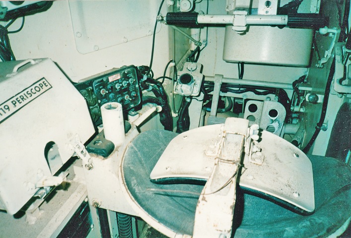
A closer view of the driver's position is presented here. His seatback is folded forward, and the stowage box for the M19 infrared periscope is nicely labeled. The steering selector lever can be seen to the right of the air cleaner. This allowed the driver to change between geared ("HI" lever position) and clutch-brake ("LO" lever position) steering. Clutch-brake steering was to be used with the transmission shift lever in the "1-2" position, and the vehicle wasn't to be switched to LO steering at speeds above 5mph (8kph) nor driven in LO steering at speeds above 10mph (16kph).
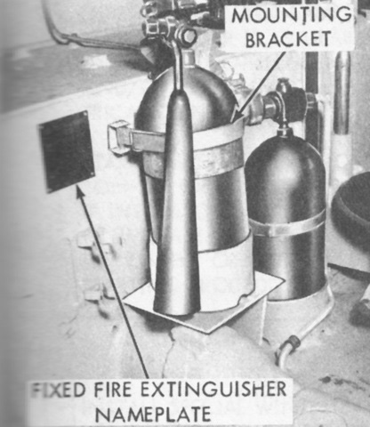
On all M114s and on M114A1s through Ordnance Vehicle Serial Number 1224, the fixed 5lb (2.3kg) CO2 fire extinguisher was mounted in the right sponson. Starting with serial number 1225, the fixed extinguisher was moved to behind the driver's seat. The fixed extinguisher was used to smother fires in the engine compartment. In addition, a 5lb (2.3kg) CO2 portable fire extinguisher was mounted behind the driver's seat. (Picture from TM 9-2320-224-10 C9.)
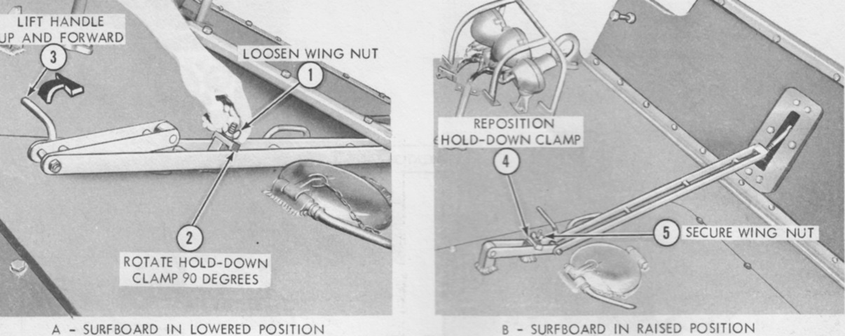
The process for deploying the surfboard is detailed here. (Picture from TM 9-2320-224-10 C4.)
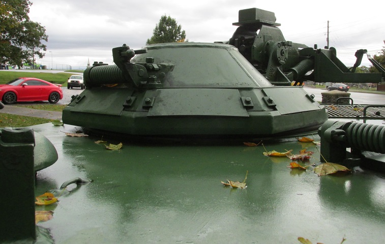
The new commander's cupola can be contrasted with the type shown in the above images. The machine gun has its travel lock deployed on this vehicle. (Picture from TM 9-2320-224-10 C4.)
The carrier is shown here from the opposite angle. (Picture from TM 9-2320-224-10 C4.)
The commander's, driver's, and observer's hatches are open on this vehicle, and both machine guns are mounted. (Picture from Tactical Vehicles.)
The commander's station is shown in this picture. 1. Vision block. 2. Electrical control box assembly. 3. Elevating mechanism handle. 4. Gun firing trigger. 5. Elevating mechanism assembly. 6. Commander's seat back rest. 7. Commander's seat. 8. Intercom box. 9. Cupola hatch cover lock handle. 10. Dome light. 11. Traverse mechanism assembly. 12. Traverse mechanism speed shift lever. 13. Traverse mechanism handle. 14. Fixed fire extinguisher instruction plate. (Picture from TM 9-2320-224-10 C4.)
The new cupola used the turret-type M2HB machine gun, which was equipped with a firing solenoid and a right-hand ammunition feed. The flexible-type M2HB used a left-hand ammunition feed. (Picture from TM 9-2320-224-10 C4.)
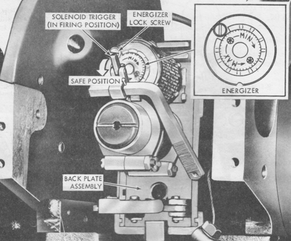
The solenoid installation is shown here, and the commander could select single shot or automatic fire from his control box. The solenoid trigger could also be operated manually in case of a failure of the electrical firing system. (Picture from TM 9-2320-224-10 C4.)
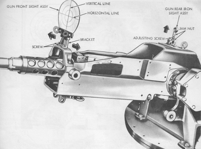
The sights for the M26 cupola are detailed in this picture. They were used for boresighting, and the gun could be aimed with the sights or via tracers. (Picture from TM 9-2320-224-10 C4.)
The observer's position is shown here. 1. Electrical connector for gas-particulate filter unit (circuit no. 10). 2. Dome light. 3. Bracket (provided for gas-particulate filter unit M8A3). 4. Binoculars bracket. 5. Personnel heater heat control knob. 6. Personnel heater duct damper handle. 7. M13 spare periscope stowage box. 8. Periscope locking knob. 9. Observer's hatch cover. 10. M13 periscope. 11. Hatch cover locking lever. 12. Personnel heater air inlet grille (crew compartment). 13. Jump seat. 14. M25 spare periscope stowage box. 15. M14 rifle retaining clips. (Picture from TM 9-2320-224-10 C4.)
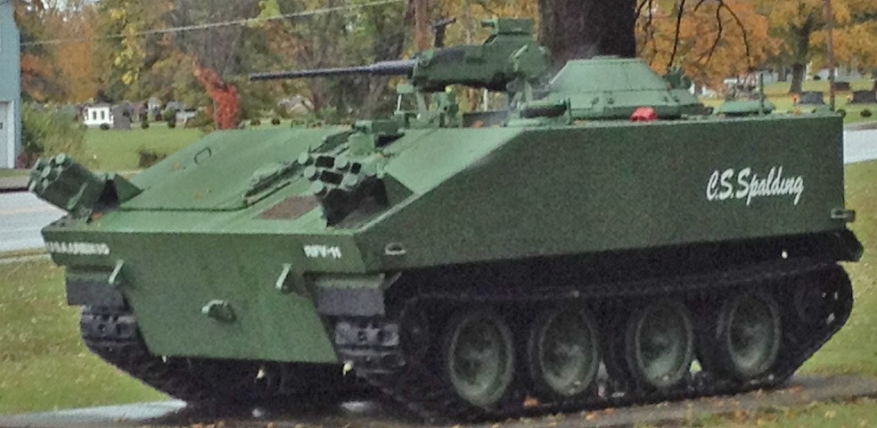
This vehicle sports some modifications related to testing it underwent as a robotic fighting vehicle, but it allows us to see the M26 cupola fitted to the M114A1. The smoke grenade launchers on the hull and the cameras located on the front hull and the machine gun mount would not be expected on a service vehicle. The modifications were performed by Charles S. Spalding and personnel from the Army Armor and Engineer Board.
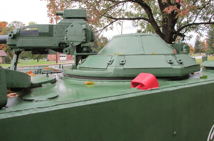
The machine gun on this vehicle is a replica, but its position and ammunition tray can be seen. The cupola travel lock points the weapon off to the vehicle's right to allow the driver access to his hatch.
Further details of the machine gun mount can be seen here.
The handle and guard for the fire extinguisher have been painted red. The hinge mechanism for the driver's hatch is at the left of the image.
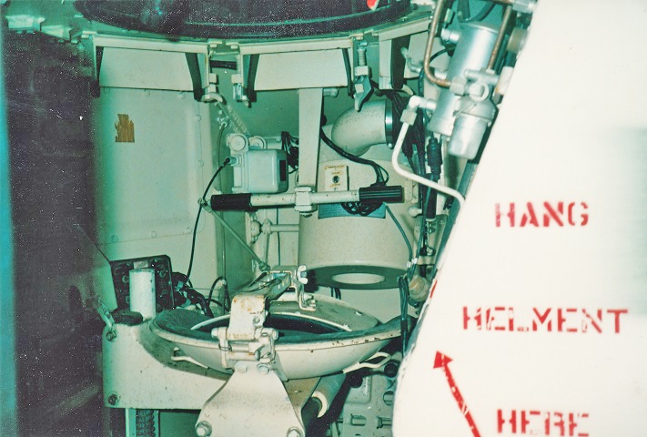
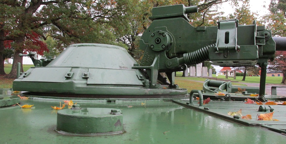
The catch and spring for the cupola door were mounted on the rear, and the observer's hatch and support can be seen in the foreground.
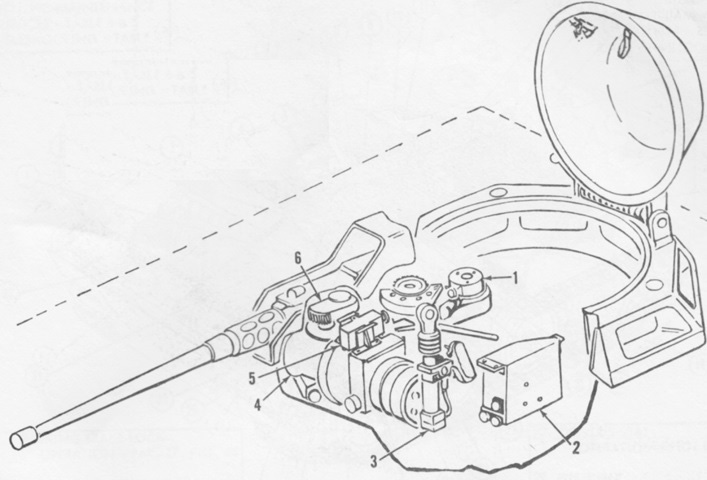
The cupola with hydraulic controls is sketched here. 1. Traverse mechanism. 2. Electric control box. 3. Elevating mechanism. 4. Hydraulic control assembly. 5. Interrupter valve. 6. Housing assembly (interrupter brake). (Picture from TM 9-2320-224-10 C4.)
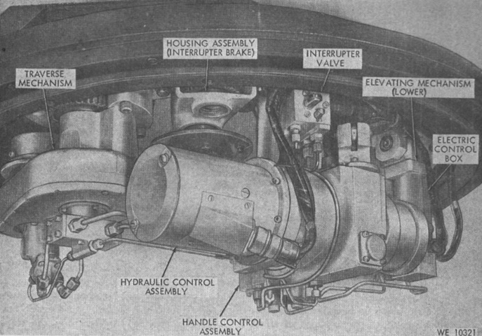
The hydraulic system is shown here from the rear. The interrupter valve prevented the cupola from traversing the machine gun over the observer's hatch and machine gun; an override button allowed the resumption of 360° traverse. (Picture from TM 9-2320-224-10 C4.)
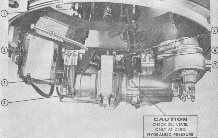
The hydraulic system is seen here from the front. 1. Elevating mechanism (upper portion). 2. Elevating control box. 3. Elevating mechanism (lower portion). 4. Hydraulic control assembly (power unit). 5. Interrupter valve. 6. Housing assembly (interrupter brake). 7. Traverse mechanism. (Picture from TM 9-2320-224-10 C4.)
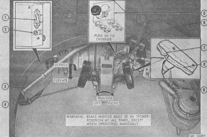
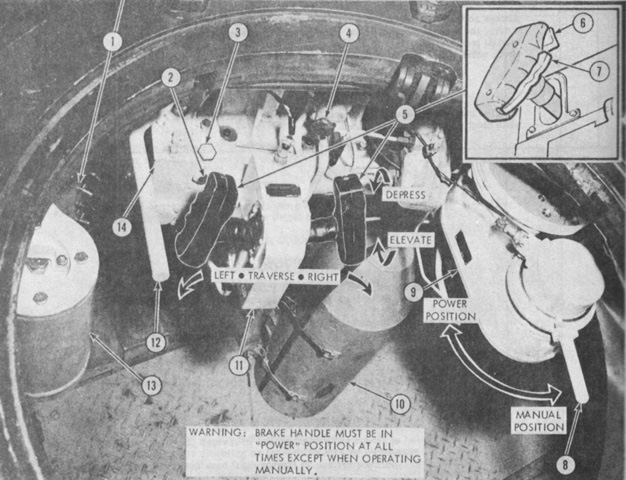
The cupola controls are detailed in this picture. 1. Cupola power switch. 2. Armament control switch. 3. Manual pump handle. 4. Handle control assembly. 5. Interrupter valve. 6. Reservoir level sight gage. 7. Firing trigger. 8. Magnetic brake switch. 9. Traverse mechanism brake handle. (Picture from TM 9-2320-224-10 Operator's Manual for Carrier, Command and Reconnaissance: Armored, M114/M114A1 (2320-860-2349) (2320-987-9536 C4.)
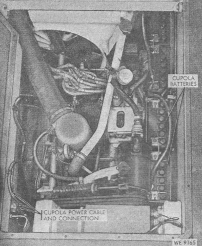
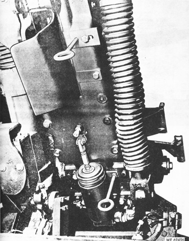
Two additional batteries were added in the engine compartment to supply the electric power needed for the hydraulic system. (Picture from TM 9-2320-224-10 C4.)
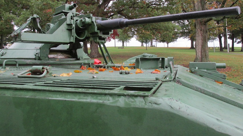
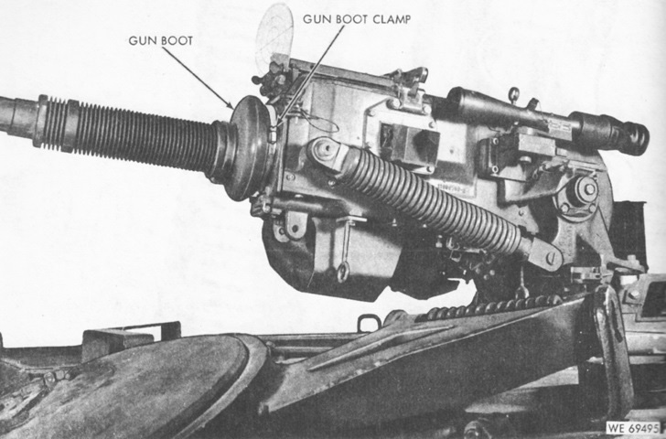
The 20mm gun makes a striking contrast to the .50cal machine guns on the vehicles above. (Picture from TM 9-2320-224-10 C9.)
The ammunition feed can be seen from this angle. (Picture from TM 9-2320-224-10 C9.)
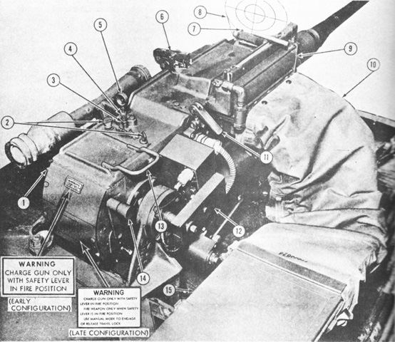
The top of the new armament and cupola interior controls are detailed in this sketch. 1. Link aligner/lubricator assembly. 2. Flexible ammunition chute. 3. Gun charging mechanism. 4. Gun safety mechanism. 5. Ammunition feed box assembly. 6. Traverse mechanism brake handle. 7. Elevation/traverse control handle. 8. Interrupter valve override button. 9. Manual hydraulic pump handle. 10. Gun fire control box. 11. Manual firing mechanism. 12. Sighting and fire control. 13. Cartridge case and link ejector chutes. 14. 20mm automatic gun M139. (Picture from TM 9-2320-224-10 C9.)
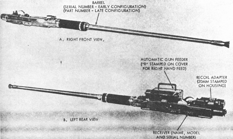
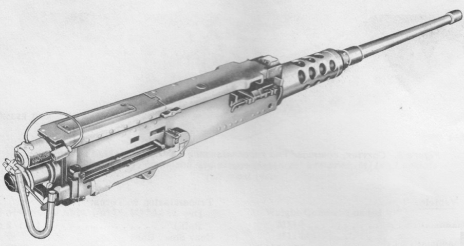
The M139 weighed 161.3lb (73.17kg) with the automatic gun feeder and recoil adapter. It was 100.9" (256.3cm) long overall and had a cyclic rate of 800-1,050 rounds per minute. Recoil length was .63"-1" (1.6cm-2.5cm). (Picture from TM 9-2320-224-10 C9.)
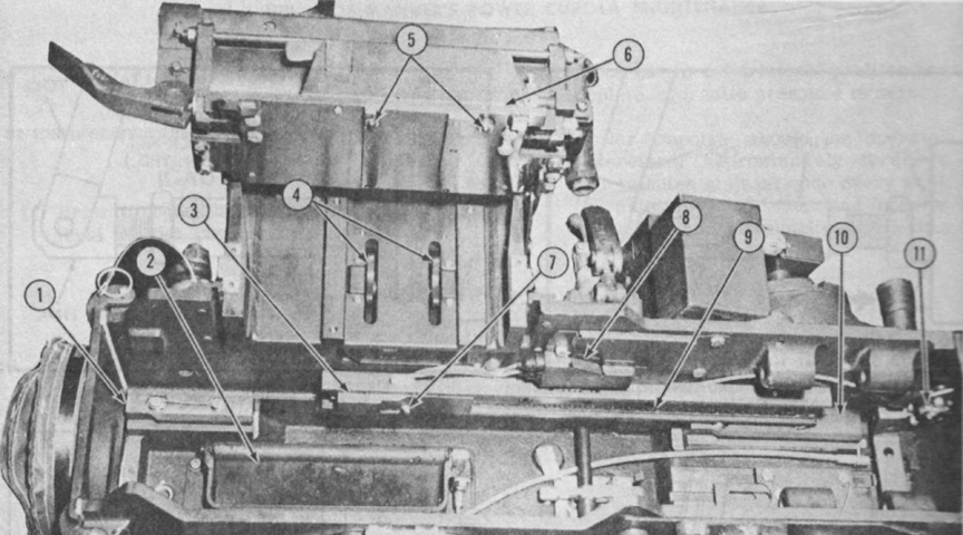
The right side of the gun cradle is seen here with the weapon removed. 1. Front recoil guide (2). 2. Cartridge case ejection chute. 3. Charging mechanism slide. 4. Link aligner sprocket. 5. Ammunition lubricating plunger (2). 6. Link aligner cover. 7. Charging mechanism pawl. 8. Wiring harness guard. 9. Charging mechanism chain. 10. Rear recoil guide (2). 11. Safe to charge micro switch. (Picture from TM 9-2320-224-10 C9.)
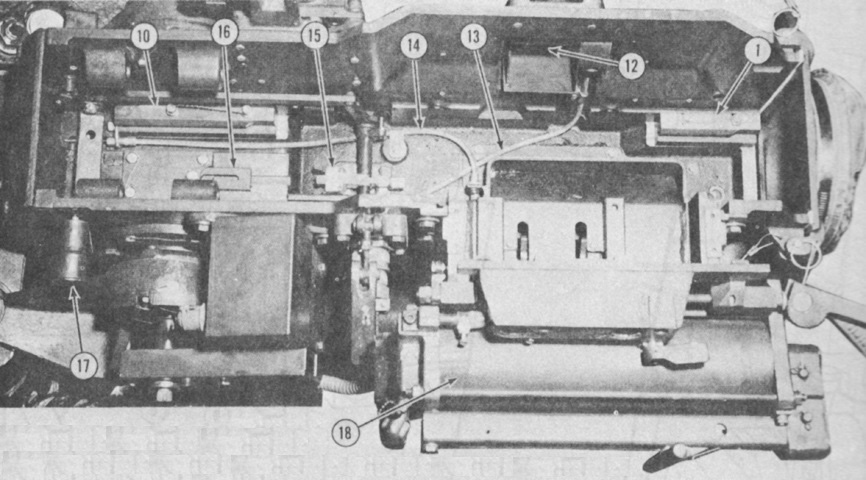
The left side of the gun cradle is seen here with the weapon removed. 1. Front recoil guide (2). 10. Rear recoil guide (2). 12. Link ejection chute. 13. Link ejection chute cable. 14. Cartridge case ejection chute cable. 15. Firing pad lever. 16. Safety lever safety plate. 17. Safe/fire safety lever. 18. Lubricator cylinder assembly. (Picture from TM 9-2320-224-10 C9.)
The bottom of the cradle and feed system is detailed in this image. 1. Flexible ammunition chute cover. 2. Cradle drain plug. 3. Ammunition cartridge case ejection chute. 4. Equilibrator. 5. Firing lever assembly adjusting screw. 6. Gun lower sight. 7. Electrical firing solenoid. 8. Cupola-to-firing solenoid electrical wiring harness. 9. Cupola-to-heater element and charger mechanism wiring harness. 10. Ammunition feed box last round switch cover. 11. Ammunition feed box. 12. Gun electrical charging mechanism. 13. Hydraulic elevating cylinder. (Picture from TM 9-2320-224-10 C9.)
The top of the cradle and feed system is detailed in this image. 1. Manual firing lever. 2. Peep sight mounting screw (2). 3. Jam nut. 4. Adjusting screw. 5. Rear peep sight. 6. Top cover plate hold-open latch. 7. Speed ring thumbscrew (2). 8. Speed ring. 9. Link aligner/lubricator assembly. 10. Flexible feed chute dust cover. 11. Top cover plate locking lever. 12. Gun charging mechanism. 13. Top cover plate handle. 14. Safe/fire safety lever. 15. Ammunition feed box. (Picture from TM 9-2320-224-10 C9.)
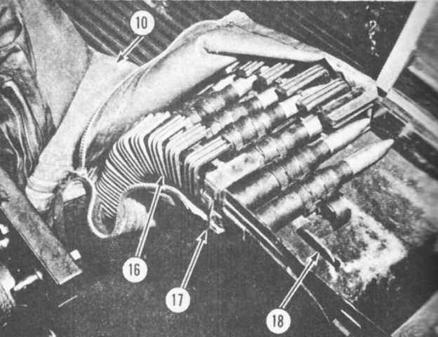
The above image of the ammunition feed is continued. 10. Flexible feed chute dust cover. 16. Flexible feed chute. 17. Flexible feed chute spring latch (4). 18. Ammunition last round stop. (Picture from TM 9-2320-224-10 C9.)
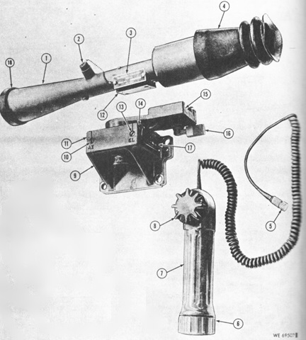
The telescope M120 could be mounted on the left of the gun cradle via the telescope mount M148. The instrument light M52E1 provided illumination to the reticle. The M120 was a 6x straight tube-type with a 92.5-mil field of view. 1. M120 telescope. 2. Light well cap. 3. Nameplate. 4. Eyeshield. 5. Lamp cap. 6. Case cap. 7. M52E1 instrument light. 8. Light rheostat knob. 9. M148 telescope mount. 10. Azimuth boresight adjustment screw. 11. Azimuth boresight clamping screw. 12. Telescope mounting plate. 13. Elevation boresight adjustment screw. 14. Elevation boresight clamping screw. 15. Dovetail mount. 16. Clamping lever. 17. Nameplate. 18. Cap assembly. (Picture from TM 9-2320-224-10 C9.)

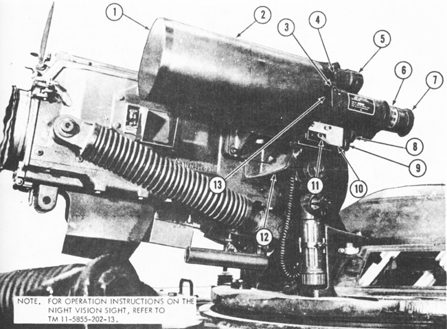
The above instruments are installed in this picture. 1. M120 telescope. 2. M52E1 instrument light housing. 3. Telescope nitrogen purging and charging screw. 4. M120 telescope mount clamping lever. 5. Elevation boresight clamping screw (hidden). 6. M52E1 instrument light. 7. Bracket, clamp, and wing nut. 8. Rheostat light knob (controls illumination for M120 telescope). 9. Elevation boresight adjustment screw. 10. M148 telescope mount. 11. Azimuth boresight adjustment screw. 12. Azimuth boresight clamping screw. 13. Link ejection chute. 14. Cartridge case ejection chute. 15. Telescope lens cap. (Picture from TM 9-2320-224-10 C9.)
The crew-served weapon night vision sight AN/TVS-2A could also be mounted on the gun cradle. It was a battery-powered 7x electro-optical device with a 108-mil field of view. 1. Lens cap. 2. Night vision sight AN/TVS-2A. 3. Objective lens focus knob. 4. Rotary control (6-position) switch knob. 5. Battery cap. 6. Eyepiece focus ring. 7. Eyeshield. 8. Elevation boresight knob. 9. Azimuth boresight knob. 10. Boresight assembly. 11. Sight-to-mounting bracket lock knob. 12. Night vision sight mounting bracket. 13. Objective lens focus knob locking device. (Picture from TM 9-2320-224-10 C9.)
The gun cradle lower sight assembly is shown here. 14. Azimuth adjustment screw. 15. Azimuth clamping screw. 16. Elevation adjustment screw. 17. Elevation clamping screw. 18. Lower sight assembly (early configuration). (Picture from TM 9-2320-224-10 C9.)
Late-production cradle assemblies and elevation mechanisms were modified to the configuration in this picture. (Picture from TM 9-2320-224-10 C9.)
The late cradle is shown from the left here. (Picture from TM 9-2320-224-10 C9.)
The cupola controls are labeled in this image. 1. Gun fire control box assembly. 2. Power pack housing assembly sight gage window. 3. Power pack housing assembly filler plug. 4. Interrupter valve override button. 5. Elevation/traverse dual control handle. 6. Firing trigger. 7. Magnetic brake switch. 8. Traverse mechanism brake handle. 9. Traverse mechanism. 10. Night vision sight stowage box. 11. Handle control assembly. 12. Manual pump handle. 13. Accumulator. 14. Power pack housing assembly. (Picture from TM 9-2320-224-10 C9.)
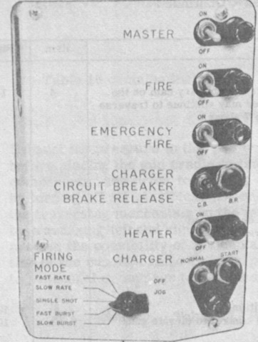
The gun fire control box is highlighted in this picture. Typically, the gun would cease firing electrically when the last linked cartridge passed the last round switch on the feed box. This would leave 25 rounds in the chute, and the gun could be made to continue firing electrically by activating the EMERGENCY FIRE switch. (Picture from TM 9-2320-224-10 C9.)
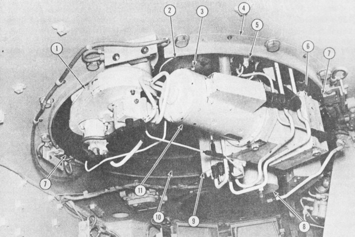
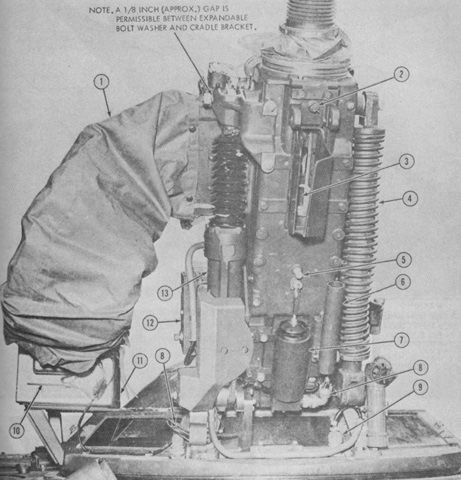
The cupola hydraulic system is detailed here. 1. Traverse mechanism. 2. Traverse brake disc plate. 3. Traverse brake disc plate screw (4) and lockwire. 4. Electrical contact ring guard. 5. Interrupter valve. 6. Power pack housing assembly. 7. Electrical contact ring brush (4). 8. Accumulator. 9. Elevation/traverse handle control assembly. 10. Electrical contact ring. 11. Motor and pump assembly. (Picture from TM 9-2320-224-10 C9.)
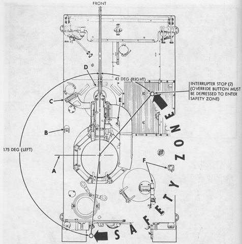
This guide illustrates the typical depression limitations for the vehicle, although individual machines could vary a bit. A. Left side of vehicle (226 mils depression). B. Fire extinguisher lever guard (51 mils maximum depression). C. Hatch cover hinge support (180 mils maximum depression). D. Driver's hatch cover (173 mils maximum depression). E. Travel lock (folded position) (141 mils depression). F. 7.62mm machine gun (either position) (140 mils minimum elevation). (Picture from TM 9-2320-224-10 C9.)
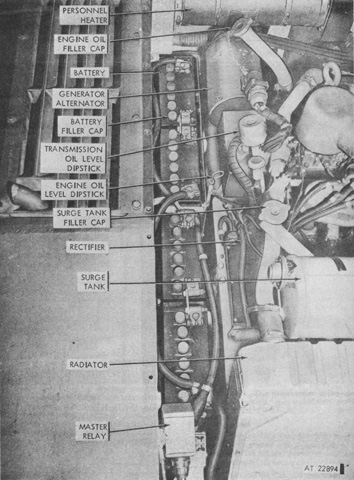
The M114A1E1 also had four batteries installed to power the cupola hydraulics. (Picture from TM 9-2320-224-10 C9.)
The AN/TVS-2A is mounted on this carrier. (Picture taken 1 Sep 1975; available from the National Archives.)
