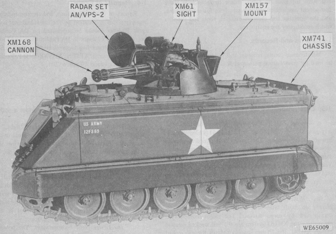
20mm Self-propelled Antiaircraft Artillery Gun M163 Vulcan Air Defense System.
The M113A1 parentage of the M163 is obvious. The gun turret is open-topped, and the driver retains his normal position in the vehicle's left front corner, though the commander was moved to the right rear behind the gun mount. (Picture from TM 9-2350-300-10.)
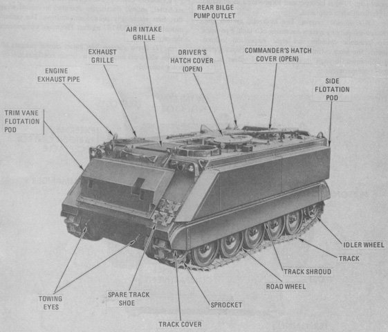
The modified carrier was designated M741, and was fitted with a high-displacement trim vane and side flotation pods due to the weight imposed by the armament. (Picture from TM 9-2350-300-10.)
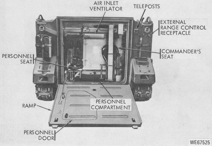
The commander was at the right rear of the hull, and a 2-man personnel seat occupied the opposite corner. (Picture from TM 9-2350-300-10.)
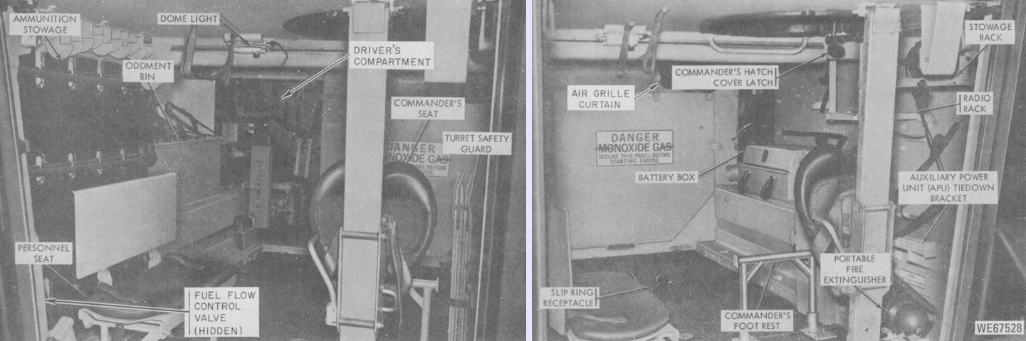
The left and right sides of the personnel compartment are shown on the left and right, respectively. Compared to the personnel carrier, the portable fire extinguisher was moved to the right rear corner of the hull, and the battery box was moved forward. A dismountable auxiliary power unit was stowed to the commander's right. (Picture from TM 9-2350-300-10.)
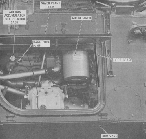
External access to the power plant compartment remained under the trim vane, which has been disconnected and folded down. (Picture from TM 9-2350-300-10.)
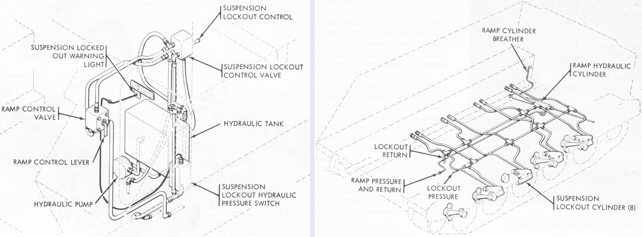
In addition to operating the rear ramp, the M741's hydraulic system actuated eight suspension lockout cylinders to provide a more stable firing platform. The ramp cylinder and suspension cylinders were connected through individual control valves at the driver's position. The hydraulic system used 8 quarts (7.6L) of fluid. (Picture from TM 9-2350-300-10.)
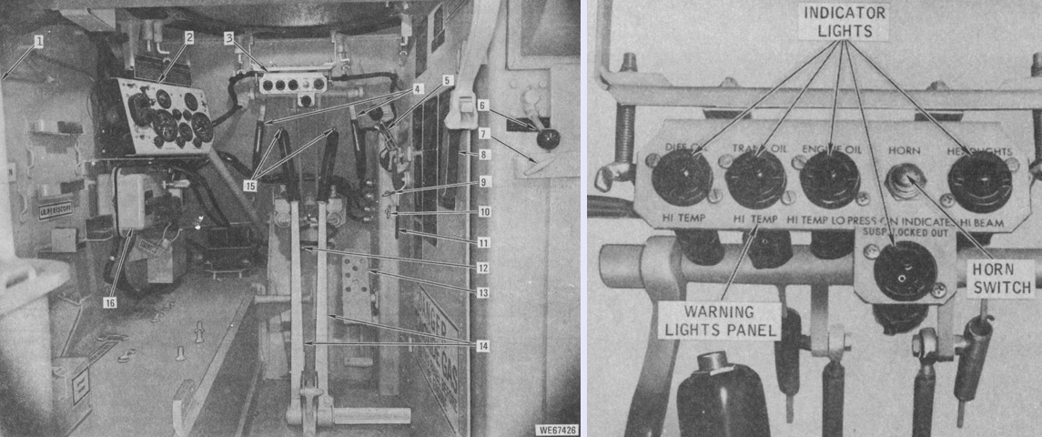
The driver's position is labeled here, with his seat removed for clarity. As seen on the right, in addition to the standard warning lights carried over from the personnel carrier, a light indicating that the suspension was locked out was added underneath the horn switch. 1. Fixed fire extinguisher (hidden). 2. Instrument panel. 3. Warning lights panel. 4. Pivot steering levers. 5. Range selector. 6. Suspension lockout control. 7. Power plant access panel handle. 8. Ramp locking handle. 9. Fuel cutoff control. 10. Hand throttle control. 11. Ramp actuating lever. 12. Beam selecting switch. 13. Accelerator pedal. 14. Differential steering levers. 15. Brake lock buttons. 16. Master switch panel. (Picture from TM 9-2350-300-10.)
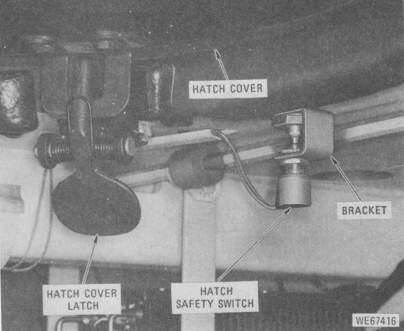
The driver's and commander's hatches featured safety switches to prevent injury from the moving gun when the hatch was open. (Picture from TM 9-2350-300-10.)
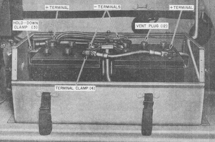
The battery box retained the same two 12-volt batteries connected in series inherited from the carrier, but was moved forward from its previous location. (Picture from TM 9-2350-300-10.)
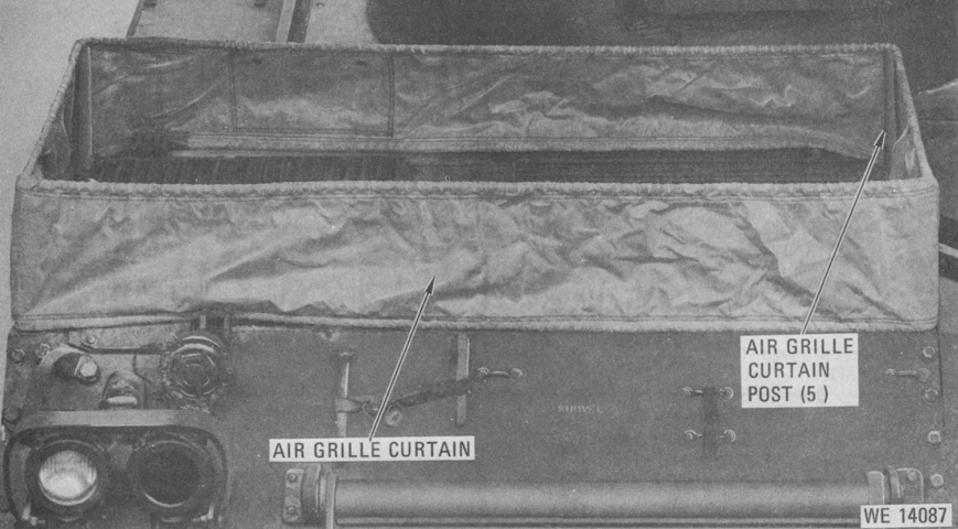
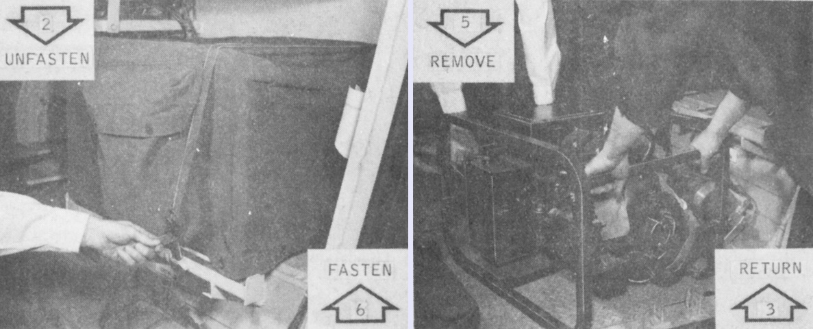
Despite the high-displacement trim vane and flotation pods, the vehicle's freeboard when operating in water was such that an air grille curtain needed to be installed. With the gun travel lock in the stowed position, the engine exhaust was turned to the rear, and five curtain posts were inserted into pins around the air grilles. The curtain was then stretched around the posts, and the bottom of the curtain was fitted into the recesses of retainers under the posts. (Picture from TM 9-2350-300-10.)
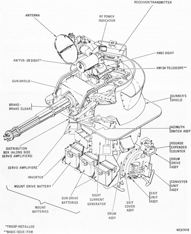
An overview of the gun mount M157 is provided. It was bearing-mounted to a plate attached to the top deck of the carrier. (Picture from TM 9-2350-300-10.)
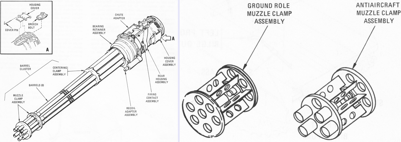
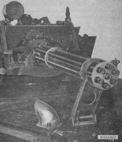
The 20mm gun M168 was ~72" (~180cm) long overall, with the six barrels each 60" (150cm) long. The assembly rotated clockwise as viewed from the muzzle. The gun weighed ~134lb (~60.8kg) without the barrels, recoil adapters, and mid-barrel muzzle clamps, and each barrel weighed ~18lb (~8.2kg). Two muzzle clamps were provided, shown on the right. The antiaircraft clamp imparted a wade-angle dispersion to the projectiles, while the ground role clamp provided a more concentrated dispersion. (Picture from TM 9-2350-300-10.)
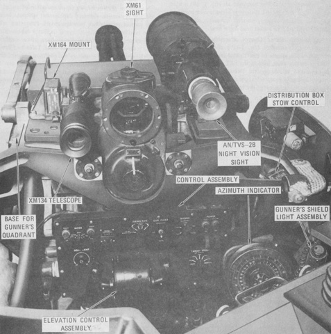
The upper front of the gun mount is labeled. (Picture from TM 9-2350-300-10.)
The gun mount's control assembly is seen from behind. (Picture from TM 9-2350-300-10.)
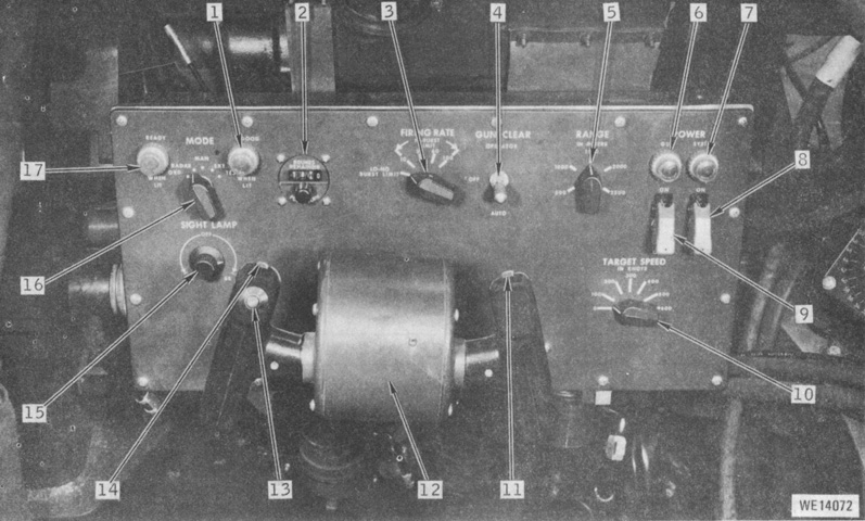
A more detailed look at the control assembly is provided here. 1. Good-when-lit indicator [lit in test mode as part of prefire check]. 2. Rounds remaining counter [indicated rounds remaining in ammunition drum in 10-round increments; manually reset]. 3. Firing rate switch. 4. Gun clear switch [AUTO: gun was automatically cleared after firing; OPERATOR: gun was cleared when either action switch was closed and gun clear switch was held in this position; OFF: gun was not cleared after firing]. 5. Range in meters knob [provided estimated range in manual mode]. 6. Gun power indicator. 7. System power indicator. 8. System power switch. 9. Gun power switch. 10. Target speed knob [provided estimated target approach speed in manual mode]. 11. Trigger switch. 12. Elevation control assembly. 13. Sight cage switch [electrically caged sight gyro]. 14. Trigger switch (dummy). 15. Sight lamp knob. 16. Mode switch [GRD: lead computing feature of sight was not used; RADAR: target range and speed were set into the system automatically by the radar; MAN: target range and speed were set into the system manually by the operator; EXT: range data was supplied by the external range control; TEST: self-test circuitry in sight current generator were activated]. 17. Ready-when-lit indicator [indicated when radar was operational after its 2-minute warmup]. (Picture from TM 9-2350-300-10.)
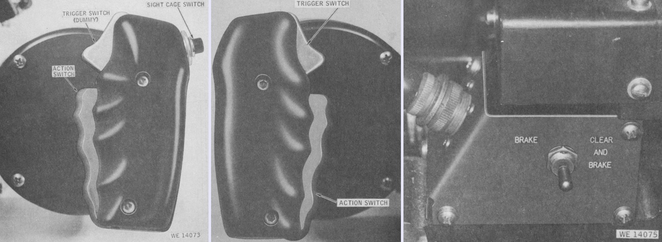
The gunner's left and right grip assemblies are above at the left and center, respectively. When either of the action switches were closed, the gun was able to be maneuvered by the elevation control assembly. The BRAKE-BRAKE AND CLEAR switch on the right released the gun motor drive brake when held in the BRAKE position; when held in the BRAKE AND CLEAR position the gun motor drive brake was released and the ammunition feeder was declutched so that ammunition cycling was halted. The switch was sprung to return to the center of position. (Picture from TM 9-2350-300-10.)
The declutching feeder assembly was used to halt the cycling of ammunition in conjunction with the gunner's BRAKE AND CLEAR switch selection. (Picture from TM 9-2350-300-10.)
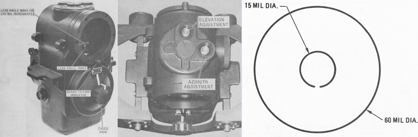
The M61 was a gyro-stabilized, lead computing sight whose housing was mounted so that it was aligned with the gun axis. The reticle was composed of two circles, the outer of 60 mils diameter and the inner of 15 mils diameter. The reticle would displace from the gun axis after the fire control solution was calculated, so that the gunner had only to re-center the target in the reticle for the burst to arrive at the proper point in space where the target would be. The sight gyro could be electrically caged to prevent damage during slewing, or mechanically caged by the caged knob. When mechanically caged, the reticle was depressed by 7.5 mils to provide correct aiming for fixed targets when used in the ground role. The M61 was 14¼" (36.20cm) high, 12¼" (31.12cm) wide, 10½" (26.7cm) deep, and weighed 31lb (14kg). (Picture from TM 9-2350-300-10.)
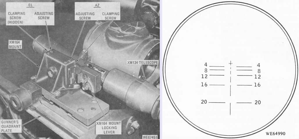
The straight telescope M134 was used when engaging ground targets. Its reticle was numbered in hundreds of meters, with the center cross used for boresighting. (Picture from TM 9-2350-300-10.)
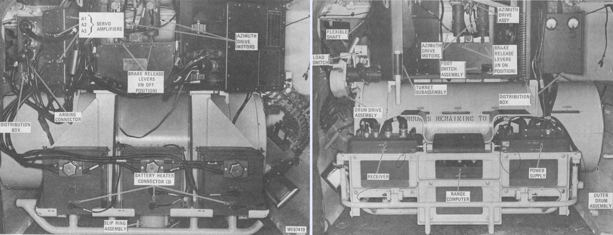
The lower portion of the gun mount is seen from the front and rear in the left and right above, respectively. Three nickel-cadmium batteries provided power, with the center and left-hand batteries powering the gun drive and loading motors, while the right-hand battery powered all the gun mount's other circuits. The ammunition drum was built up from inner and outer drum assemblies. The outer drum housed partitions that held the ammunition in a radial pattern on the outer drum's inner surface, and it also contained electrical and mechanical devices that stopped loading when the drum was full and prevented the drum from being completely emptied. The inner drum was a rotating double helix that, when actuated by the drum drive assembly, slid ammunition along the partitions of the outer drum through the scoop disc assembly to the exit cover assembly. (Picture from TM 9-2350-300-10.)
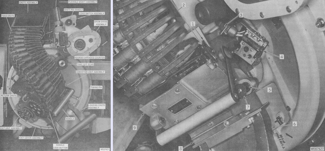
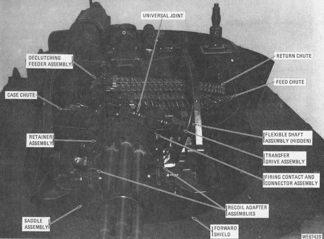
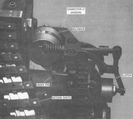
The lower portion of the gun mount is shown from the left, with a detailed view given in the right-hand image. The exit unit assembly removed ammunition links from the rounds during loading and fed the rounds to the exit cover assembly. During firing, the exit unit assembly transferred rounds from the exit cover assembly to the conveyor elements in the conveyor unit assembly. The drum drive had three modes of operation: in fire mode, the flexible shaft was linked to the exit cover gears so that the inner drum was driven in the feeding direction. In the load mode, a motor on the drum drive assembly spun the exit cover assembly gears in the direction opposite to that of fire mode. In neutral mode, the exit cover assembly gears could be driven manually for maintenance or timing. The handle was used to lock the conveyor unit into the loading or firing positions. During loading, it was locked in an inoperative condition away from the exit unit assembly. 1. Spring clip. 2. Feed chute (return chute hidden). 3. Connector (A7A2J1 and W4P3). 4. Conveyor detection assembly. 5. Positioning rail. 6. Loading chute. 7. Stop. 8. Exit unit. 9. Conveyor unit assembly. (Picture from TM 9-2350-300-10.)
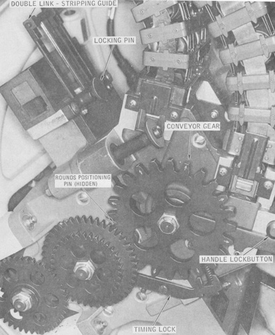
The exit and conveyor units are highlighted here. The double link-stripping guide led ammunition to the link stripper during loading; the locking pin held the double link-stripping guide in the loading or firing positions. The timing lock held the conveyor gear in the correctly timed position when the conveyor unit was locked in the loading position. (Picture from TM 9-2350-300-10.)
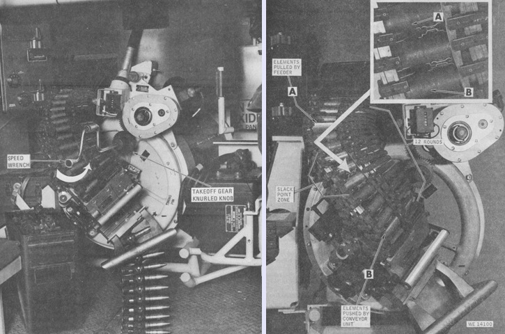
Loading the M157 mount is illustrated in these two images. A speed wrench was inserted into the takeoff gear knurled knob and turned counterclockwise until the leading ammunition link engaged the double link stripping guide's rail guide, then the wrench was further turned until two rounds were delinked. At that point the wrench was removed, and the motorized loading switch could be used. The right image shows the slack point of the feed system, above which all the element joints were extended and pulled by the feeder, and below which all the element joints were compressed and pushed by the conveyor unit. Twelve complete rounds were visible in the exposed portion of the feed chute assembly on the drum mount when the slack point was properly positioned. (Picture from TM 9-2350-300-10.)
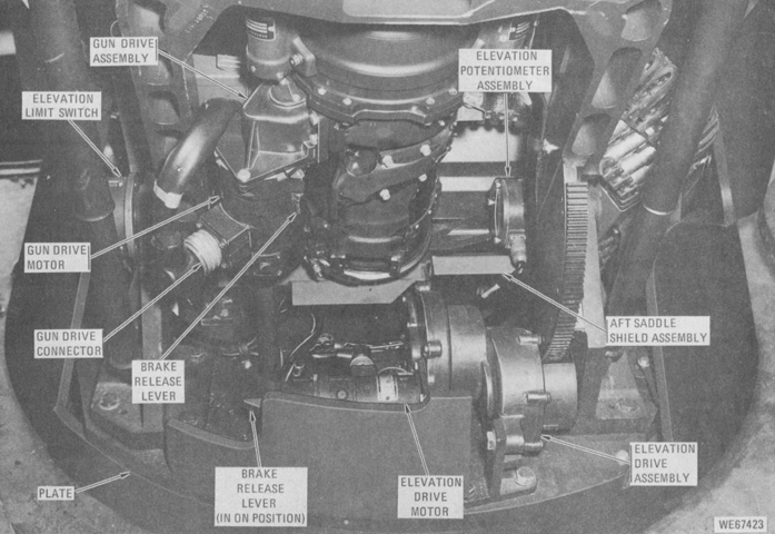
The underside of the rear of the 20mm gun can be seen, along with components making up the mount's elevation drive. (Picture from TM 9-2350-300-10.)

Components of the antenna for the AN/VPS-2 radar set are detailed on the left. The radar measured target motion along the line of sight as range and range rate, and this data was continuously fed into the sight current generator, which computed lead angles. The antenna could traverse +25° during normal operations and +27.5° for stowage, while elevation was +95° to -10° during normal operations and +96° to -73° for stowage. The split-horn feed protruded through the center of the 24" (61cm) paraboloid reflector and emitted radar energy back onto the reflector, which then focused the energy into a narrow beam. The feed was protected by brackets, and an alignment dot on the feedhorn was to be centered in the hole at the junction of the protective brackets. The antenna had a 33db gain, and was 25⅛" (63.818cm) high, 29½" (74.9cm) wide, 23¾" (60.33cm) deep, with a weight of 65lb (29kg). (Picture from TM 9-2350-300-10.)
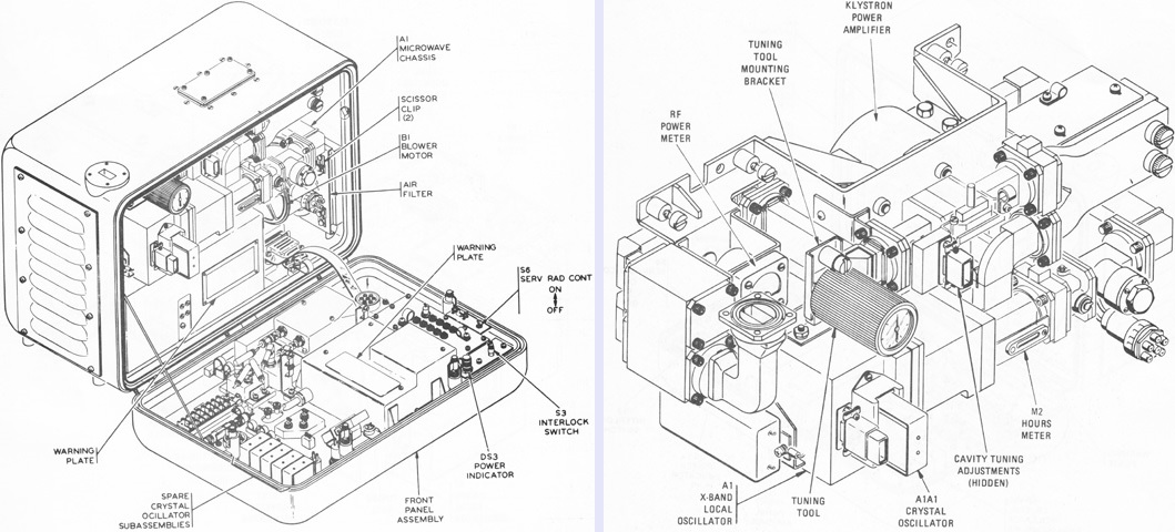
The radar's transmitter-receiver is drawn on the left. It housed the chassis that generated the high power transmission pulse for radiation by the antenna, and also picked up the return target echoes. The microwave chassis assembly has been removed from the transmitter-receiver in the right image. The radar could operate on one of six frequencies, which enabled up to six vehicles to be clustered together without interference between their radars. Frequencies were changed by the use of plug-in crustal oscillator assemblies, which required subsequent retuning of the radar's klystron power amplifier. The five spare crystal oscillator assemblies are visible secured in the front panel assembly of the transmitter-receiver. The transmitter-receiver was 12-15/32" (31.67063cm) high, 18-15/32" (46.91063cm) wide, 12-5/16" (31.2738cm) deep, and weighed 84lb (38kg). (Picture from TM 9-2350-300-10.)
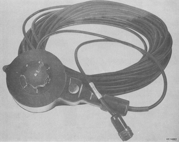
The external range control permitted an operator outside of the vehicle to enter range information into the system when it was in EXT mode. The knob was graduated in hundreds of meters, and the pushbutton switch illuminated the ready-to-fire indicator to inform the gunner when to shoot. (Picture from TM 9-2350-300-10.)
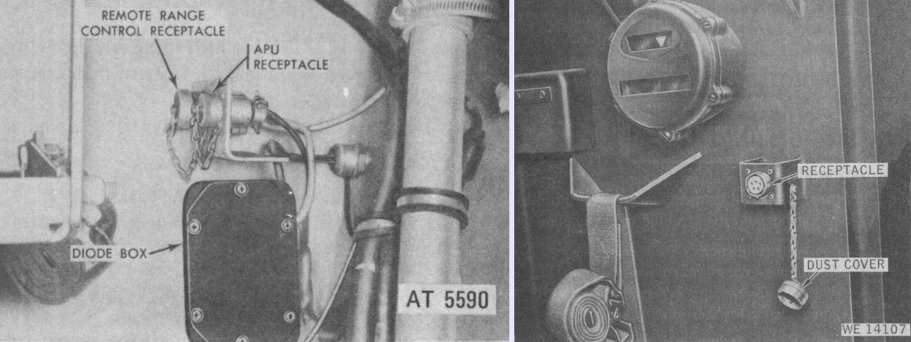
The external range control was provided with both an internal and external receptacle on the vehicle, shown above on the left and right, respectively. (Picture from TM 9-2350-300-10.)
A travel lock for the 20mm gun was installed to the right of the driver. (Picture from TM 9-2350-300-10.)
An air-cooled gasoline engine-driven generator set was stowed to the right of the commander. When deployed, it could supply all of the electrical loads in conjunction with the system batteries. It is shown stowed on the left and with its cover removed on the right. (Picture from TM 9-2350-300-10.)
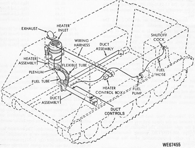
The heater setup for the M163 differed slightly from its parent carrier. (Picture from TM 9-2350-300-10.)
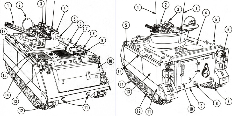
The M163A1 is drawn from the right front and left rear. Though unlabeled, the gun travel lock is mounted next to the engine exhaust. The legend for the left image is: 1. 20mm cannon M168. 2. Radar antenna (Unit 1). 3. Sight M61. 4. Mount M157A1. 5. Chassis M741. 6. Air intake grille. 7. Fire extinguisher handle. 8. Driver's hatch. 9. Periscope M17. 10. Trim vane. 11. Towing eyes. 12. Drive sprocket. 13. Lights. 14. Engine exhaust. 15. Exhaust grille. 16. Heater exhaust.
The legend for the right image is: 1. Radio antennas. 2. Telescope M134. 3. Night sight AN/TVS-2B/5. 4. Commander's hatch. 5. Bilge outlet. 6. Rear light. 7. Idler wheel. 8. Towing pintle. 9. Ramp. 10. Personnel door. 11. Track shroud. 12. Road wheel. 13. Flotation pod. 14. Track. 15. Link chute cover. (Pictures from TM 9-2350-300-10 C4.)
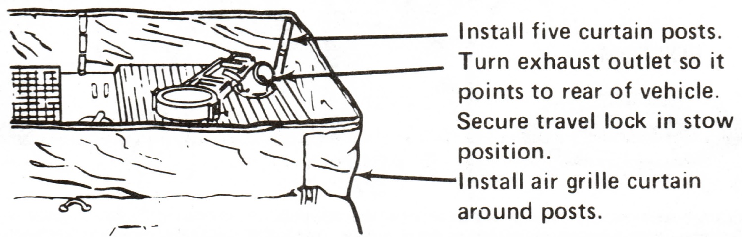
The engine exhaust can be seen in this sketch in the proper orientation for use with the air grille curtain. (Picture from TM 9-2350-300-10 C4.)
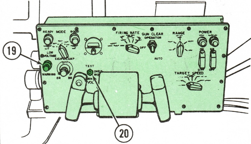
Additional controls were added for the gunner. 19. LOW VOLTAGE WARNING indicator--FLASHING: warns that system voltage has dropped below 22.0 volts; STEADY LIGHT: system voltage has dropped below 20.5 volts and has automatically been interrupted. Inverter, sight gyro, radar, and sight current generator are shut down. 20. LOW VOLTAGE switch--NORMAL: enables low voltage protective circuits to warn of approaching low voltage condition and puts system in ground mode; OVERRIDE: overrides low voltage protection circuit and allows continued operation or restoration of power under low voltage conditions; TEST: tests low voltage protective circuits. (Picture from TM 9-2350-300-10 C4.)
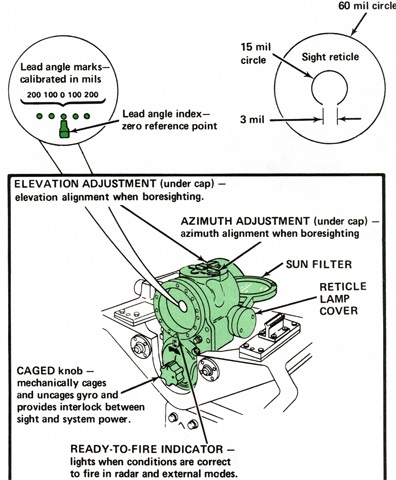
Further details of the M61 sight can be gleaned from the above drawing. (Picture from TM 9-2350-300-10 C4.)
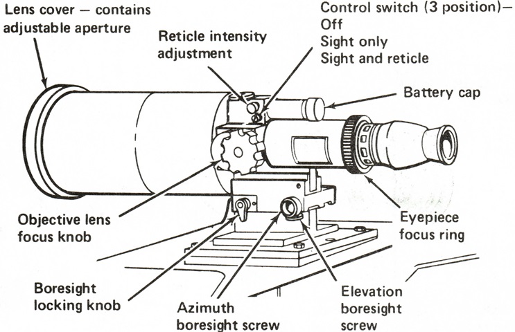
Details of the gunner's night vision sight are labeled here. It was installed to the right of the sight M61 and could also be used in ground mode. (Picture from TM 9-2350-300-10 C4.)
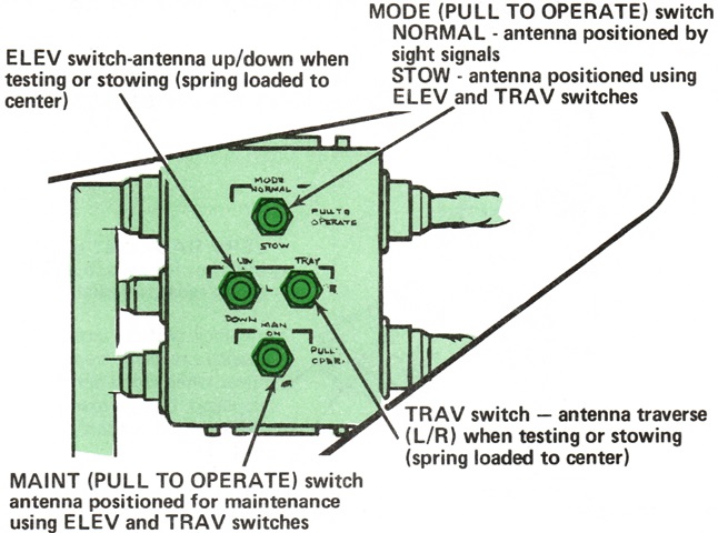
The radar antenna's stowage controls are shown here. (Picture from TM 9-2350-300-10 C4.)
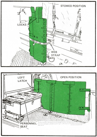
A safety guard was able to be extended across the rear compartment to shield against movement of the turret. (Picture from TM 9-2350-300-10 C4.)
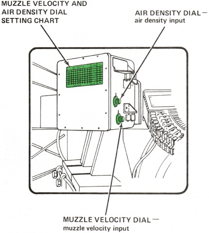
Affixed to the front of the sight current generator was a chart that referenced dial settings to input for various air density and muzzle velocities. The muzzle velocity was calculated using the ammunition type, air temperature, and barrel wear calculated via the amount of barrel cluster rounds fired up to 72,000. (Picture from TM 9-2350-300-10 C4.)
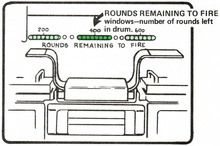
Ammunition remaining in the ammunition drum was visible through calibrated windows. (Picture from TM 9-2350-300-10 C4.)
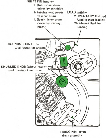
Controls for the ammunition drum drive are sketched here. A speed wrench handle could be inserted into the takeoff gear knob when loading the ammunition. (Picture from TM 9-2350-300-10 C4.)
The link disposal chute is shown reaching up to the link chute cover. (Picture from TM 9-2350-300-10 C4.)
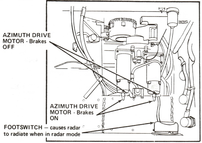
The operation of the azimuth drive brakes is indicated, and the footswitch to activate the radar is also labeled. (Picture from TM 9-2350-300-10 C4.)
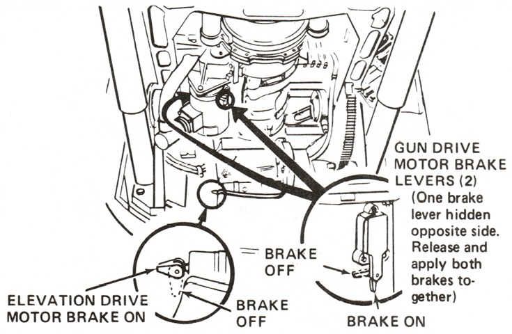
The elevation drive also had brake levers. (Picture from TM 9-2350-300-10 C4.)
One of two gun shield quick release pins and the brake-clear and brake switch are illustrated in this sketch. (Picture from TM 9-2350-300-10 C4.)
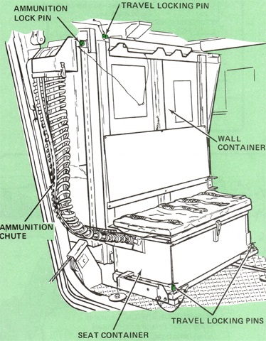
The ammunition stowage system on the left rear of the passenger compartment is shown here. Used to refill the ammunition drum, it consisted of both a wall can and a seat container. (Picture from TM 9-2350-300-10 C4.)
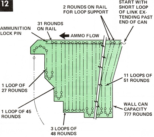
The proper way to load the wall can of the ammunition stowage system is diagrammed here. (Picture from TM 9-2350-300-10 C4.)
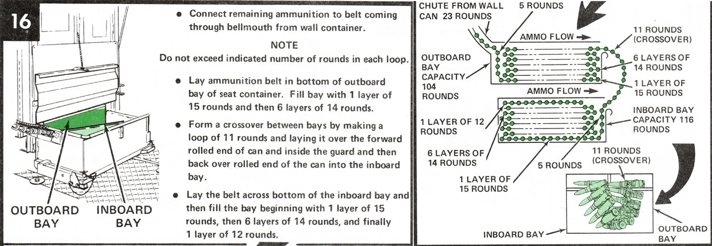
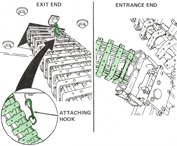
The ammunition was strung from the wall can to the seat container per the instructions above. (Picture from TM 9-2350-300-10 C4.)
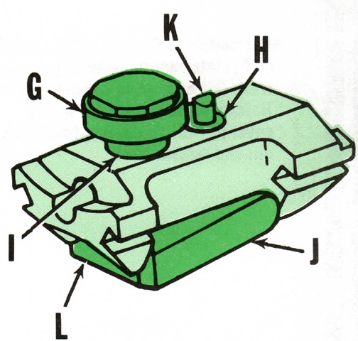
One of the six breechbolts of the ordnance is drawn here. G. Roller. H. Firing pin cam insulation. I. Bolt shaft. J. Locking block. K. Firing pin cam. L. Locking surface. (Picture from TM 9-2350-300-10 C4.)
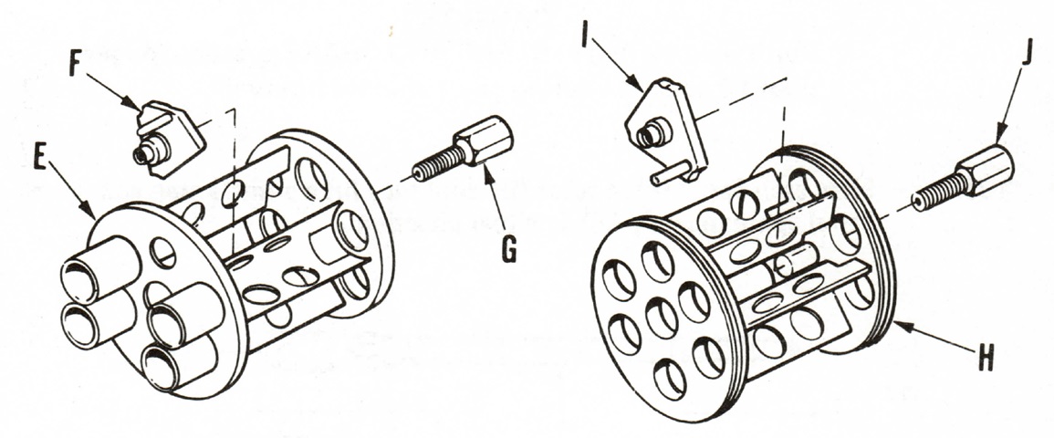
The two muzzle clamps are shown with their attachments. On the left is the elliptical 6x18 mil antiaircraft clamp that held the barrels in a slightly oval orientation, and on the right is the 5 mil ground role clamp that held the barrels in a circle. E, H. Clamp. F, I. Locking plate. G, J. Bolt. (Picture from TM 9-2350-300-10 C4.)
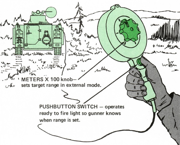
The external range control is seen in action. (Picture from TM 9-2350-300-10 C4.)
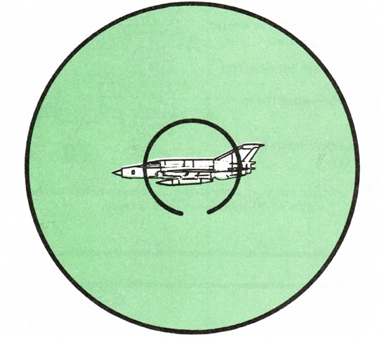
The reticle of the lead computing sight M61 is shown here. To begin an engagement in radar mode, the target was to be centered in the reticle and manually tracked as the radar footswitch was pressed. The sight and radar automatically computed the correct lead angle to hit an aerial target. After the ready-to-fire light was illuminated, the target was to be smoothly tracked for a short period until the sight settled to the correct led angle (one second in radar mode). Then with the target stationary in the center of the reticle, the trigger was to be pressed. If the ready-to-fire light blinked rapidly, the radar was being jammed, and a change to MAN mode was necessary, with the gunner inputting estimated target range and speed. (Picture from TM 9-2350-300-10 C4.)
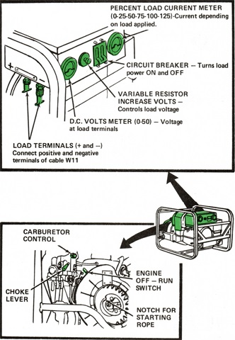
Controls for the dismountable auxiliary power unit are detailed here. (Picture from TM 9-2350-300-10 C4.)
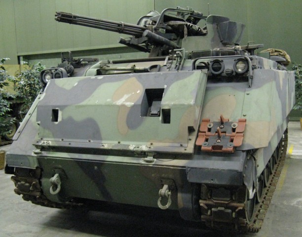
Along the vehicle's left-hand roof can be seen the square fire extinguisher activation handle cover, and directly behind this is the semi-circular link chute cover.
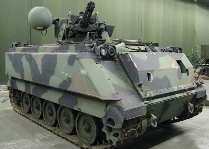
The engine exhaust indicates that this carrier is an M741A1 based on the M113A2. The improved suspension found on that vehicle was not carried over to the M741A1 due to incompatibility with the suspension lockouts. The depth of the trim vane can be better seen from this angle.
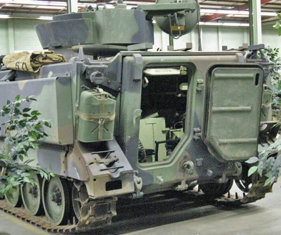
The personnel door in the rear ramp is open on this vehicle, and light can be seen shining in from the open commander's hatch in the hull rear roof. A towing pintle is mounted on the ramp below the personnel door.
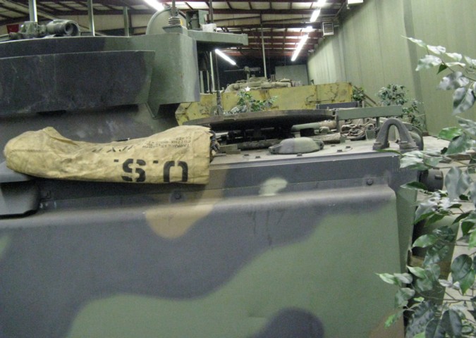
The commander's hatch opens to the vehicle's left, and the link chute cover can be seen to the left of the image under the canvas bag.
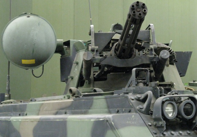
The M157A1 gun mount is seen here. The antenna for the AN/VPS-2 radar set is mounted on the turret's right side, and the sight M61 can be seen on the top of the turret above the ordnance. The partially obscured forward exhaust pipe on the vehicle's roof is for the engine, and the rear pipe is for the personnel heater.
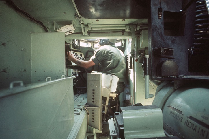
This interior view provides some scale of the room taken up by the gun turret. The driver can be seen in the background, and the large ammunition drum with its windows for viewing remaining rounds is in the picture's lower right corner. Batteries for the gun system are ahead of the ammunition drum, and the ammunition can be seen snaking up the right side of the image. (Picture taken 1 Apr 1978; available from the National Archives.)
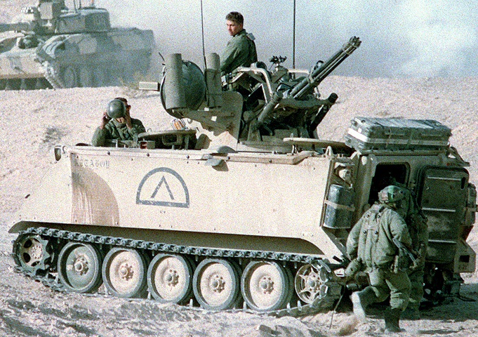
This vehicle lacks the side-mounted flotation cells and high-volume trim vane, but there would be little use for these in the California desert in any case. The commander's hatch on this vehicle is also open, and can be seen on the rear roof, just inboard of the external stowage. The vehicle in the background is an M551 Sheridan modified to resemble a T-72 tank. (Picture taken 1 Nov 1988; available from the Defense Visual Information Center.)
