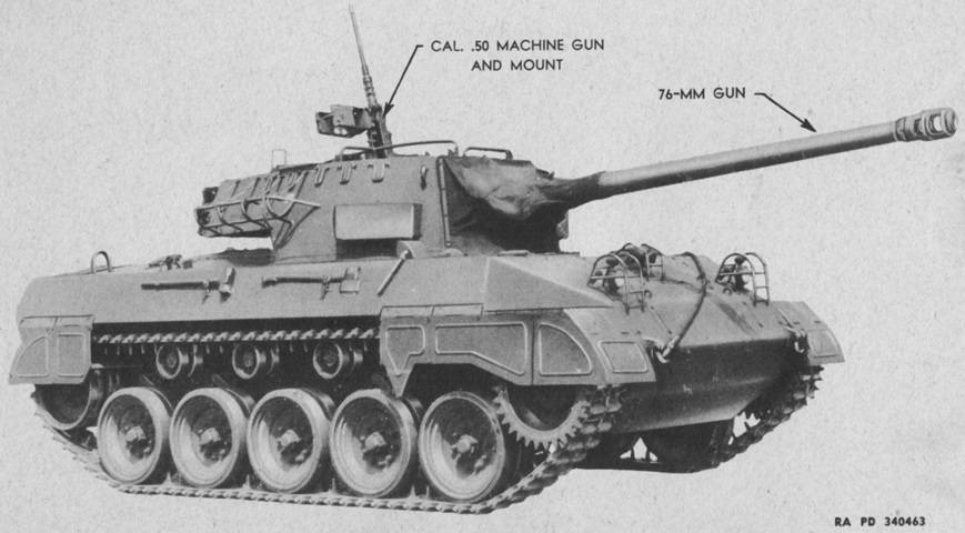
76mm Gun Motor Carriage M18.
Compared to most contemporary American armored vehicles, the large, individually-sprung road wheels of the M18's torsion bar suspension immediately stand out. Headlights and a siren are protected by brush guards on the upper front hull. (Picture from TM 9-755 76-mm Gun Motor Carriage M18 and Armored Utility Vehicle M39.)
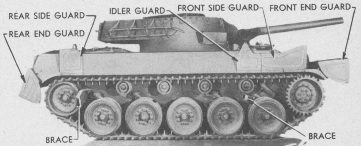
This side view showcases the hinged nature of the track guards. Attached to the sponsons, they could be raised if needed or removed completely by unscrewing the attaching screws. The front and rear end guards, along with the front and rear side guards, could be raised without disturbing the adjoining guards, but in order to raise an idler guard a front side guard needed to be raised. (Picture from TM 9-755 76-mm Gun Motor Carriage M18 and Armored Utility Vehicle M39.)
Pioneer tools and the engine hand crank were stowed on the hull rear, and a length of extra track is mounted on the turret bustle. (Picture from TM 9-755 76-mm Gun Motor Carriage M18 and Armored Utility Vehicle M39.)
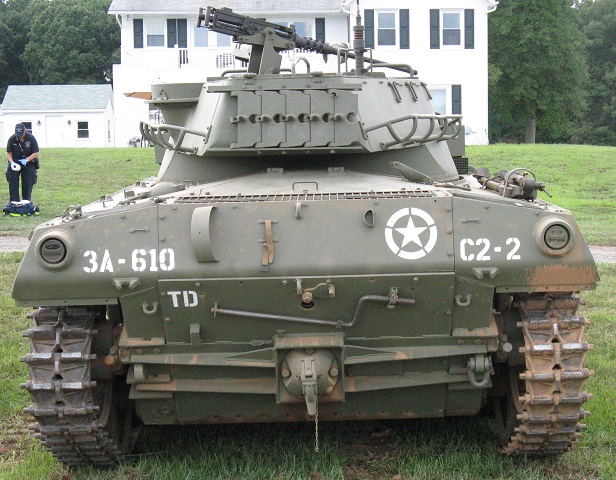
The rear of the vehicle is shown here. The engine's hand crank starter is again stowed on the hull rear door, and the right-hand fuel filler cover is open on the right side of the upper hull. Under the hand crank, reinforcement rails help support the hull rear door.
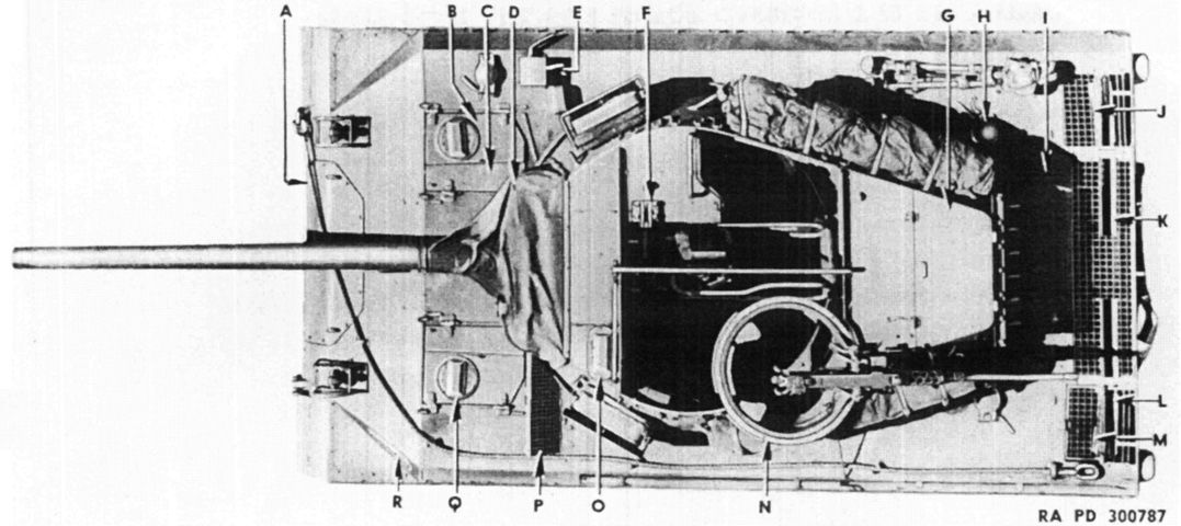
This top view showcases the partial roof in the front right corner of the turret as well as the bustle and machine gun mount. (Picture from ORD 7-8-9 SNL G-163.)
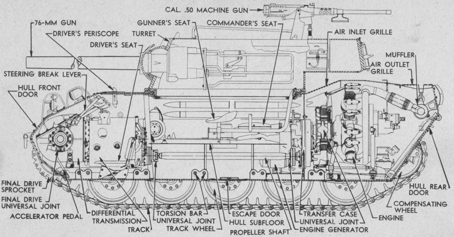
A cross-sectional view of the vehicle is shown here. Note that, in contrast to the radial-engined Sherman tanks, the propeller shaft in the M18 was lowered by the use of transfer cases; consequently it was able to be housed under the hull subfloor. This allowed the M18 to have a shorter hull despite using a similar rear-engine and front transmission setup as well as suspension internal to the hull. (Picture from TM 9-755 76-mm Gun Motor Carriage M18 and Armored Utility Vehicle M39.)
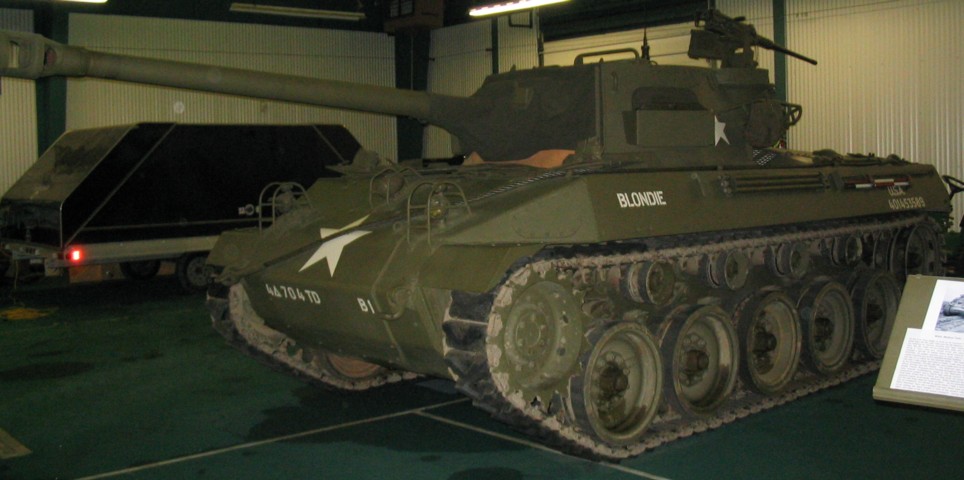
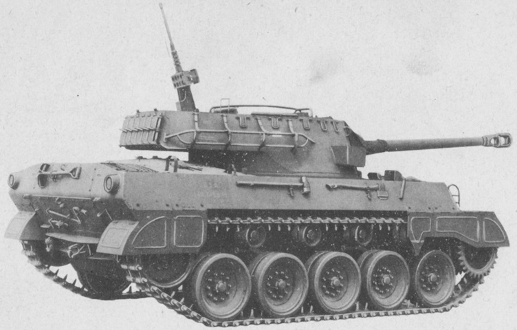
"Blondie" is sporting double-pin T85E1 track, which would be kinder to road surfaces, and stowage bins are welded to both sides of the turret. Note the different sprocket rings necessitated by the track change.
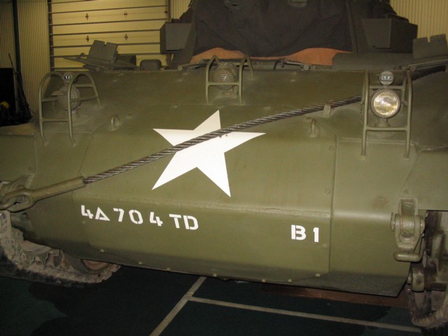
A closer view of the access hatch in the hull front is provided here. The headlight groups and siren mountings are obvious, and a tow cable is draped across the front of the vehicle. The split hatches for both drivers are open, and the periscopes mounted in the outside hatch doors are visible.
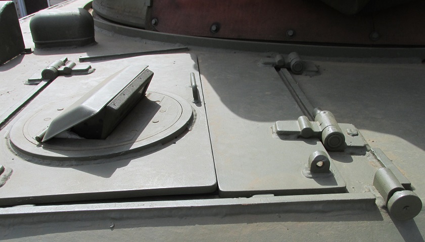
Details of the assistant driver's split hatch can be seen here. The drivers each had a periscope in the outer hatch door. A guard for the fire extinguisher external handles can be seen in the upper left of the image.
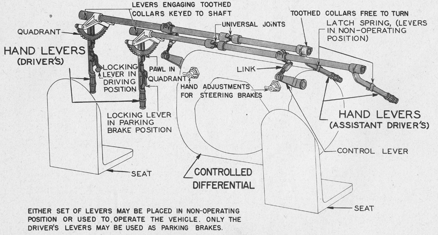
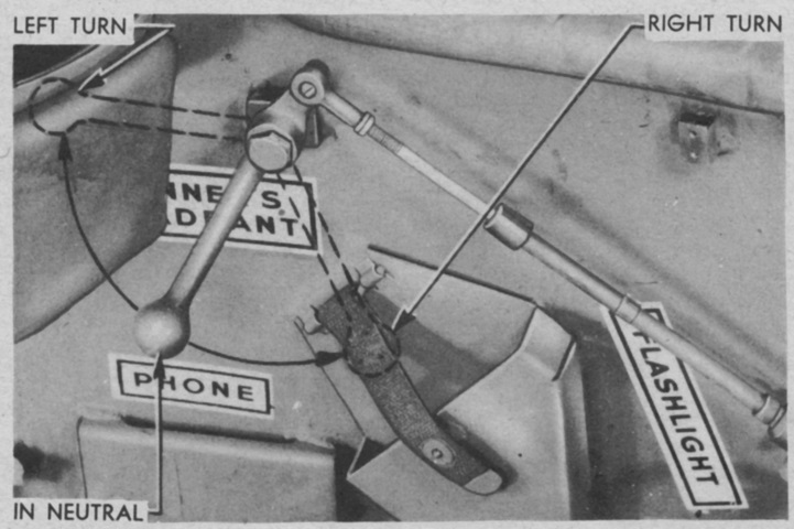
The layout of the driver's steering levers is shown here. (Picture from TM 9-755 76-mm Gun Motor Carriage M18 and Armored Utility Vehicle M39.)
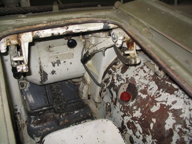
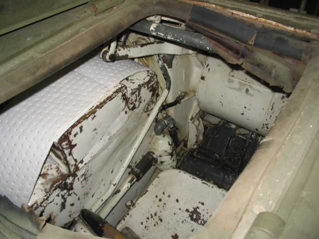
The driver steered the vehicle with two steering levers that descended from the hull roof. The accelerator pedal is visible on the floor, and the vehicle's transmission separated the two drivers.
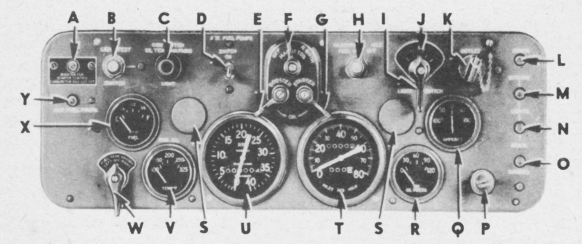
The driver's instrument panel is detailed in this picture. A. Booster coil and starter control circuit breaker. B. Test light switch (for warning light C). C. Temperature warning lamp cap (converter). D. Fuel pumps switch. E. Booster switch. F. Magnetos switch. G. Starter switch. H. Fuel cut-off switch (carburetor idle). I. Headlight, blackout light and taillight switch. J. Lock out button (part of switch I). K. Outlet plug. L. Siren circuit breaker. M. Outside lights circuit breaker. N. Inside lights circuit breaker. O. Instrument panel gages circuit breaker. P. Panel light switch. Q. Battery ammeter. R. Engine oil pressure gage. S. Instrument panel lamp cap. T. Speedometer. U. Engine tachometer. V. Engine oil temperature thermo gage. W. Fuel gage switch. X. Fuel gage. Y. Auxiliary fuel pump circuit breaker. (Picture from TM 9-755 76-mm Gun Motor Carriage M18 and Armored Utility Vehicle M39.)
The assistant driver was provided with an identical set of controls, save for parking brake pawls and quadrants.
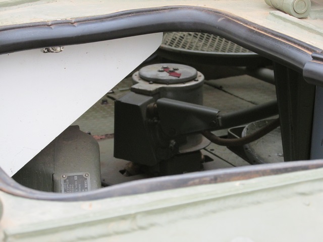
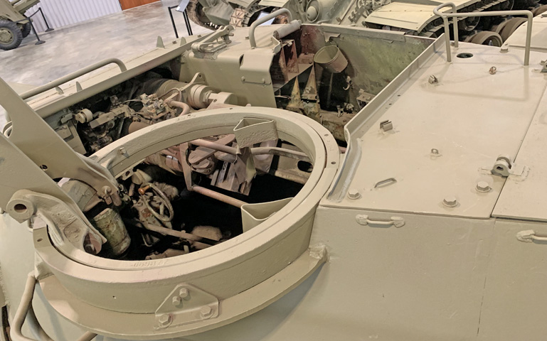
This picture is looking in through the open assistant driver's hatch. The turret slip ring that provided electrical connections to the turret is centered. Its cover featured a red arrow pointing to the hull front to help orient the turret crew. The device in the left foreground with the data plate attached is the auxiliary generator.
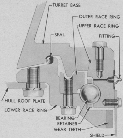
A cross-section of the turret race is shown here. Before the weapons and mounts were installed, the turret weighed 2,400lb (1,100kg). (Picture from TM 9-755 76-mm Gun Motor Carriage M18 and Armored Utility Vehicle M39.)
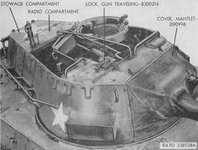
The turret is seen from above, with rear stowage compartment and radio compartment labeled. The gun travel lock was installed on top of the 76mm ready rack on the loader's side of the turret. (Picture from TM 9-1308 Ordnance Maintenance--76-mm Guns M1A1C and M1A2; Gun Mount M1 and Combination Gun Mount M62 for Combat Vehicles.)
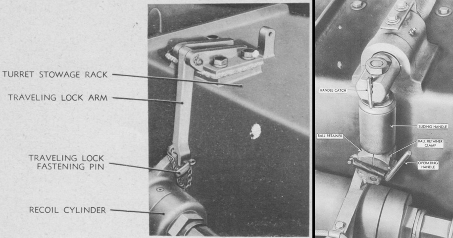
The early type of gun travel lock, used on M18s up to serial number 1857, is shown at the left. Vehicles with serial numbers of 1858 and above utilized the travel lock on the right. (Picture from TM 9-755 76-mm Gun Motor Carriage M18 and Armored Utility Vehicle M39.)
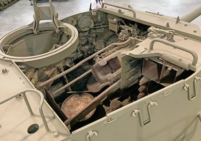
The turret interior is seen from the left rear. The lid for the stowage box on the turret bustle rear is on the right of the image, and the machine gun mount is in the foreground. The 76mm ready ammunition rack is visible on the opposite corner of the turret.
The loader's seat is visible in the right rear corner of the turret. (Picture from TM 9-1308 Ordnance Maintenance--76-mm Guns M1A1C and M1A2; Gun Mount M1 and Combination Gun Mount M62 for Combat Vehicles.)
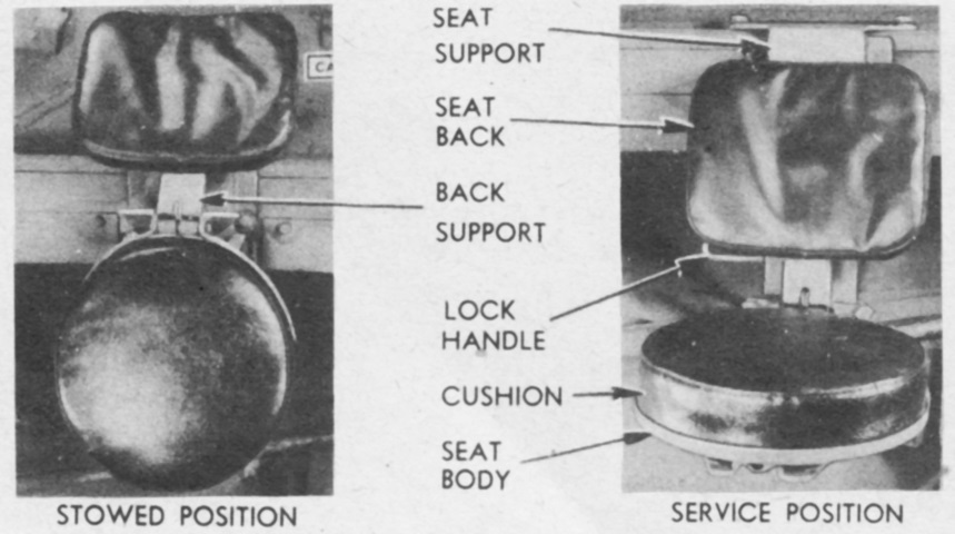
The loader's seat could be installed in the upper or lower channel of the support and could be placed in a stowed or a service position as shown. (Picture from TM 9-755 76-mm Gun Motor Carriage M18 and Armored Utility Vehicle M39.)
The other side of the turret is shown in this picture. The ready rack held nine 76mm rounds as well as .50cal ammunition boxes. Note that the breech of the gun was mounted at a 45° angle in the gun mount M1.
The ready rack is visible here at the front right corner of the turret. With the position of the ammunition stowage, the cant of the 76mm gun breech eased the loader's task when feeding the 76mm gun. (Picture from TM 9-1308 Ordnance Maintenance--76-mm Guns M1A1C and M1A2; Gun Mount M1 and Combination Gun Mount M62 for Combat Vehicles.)
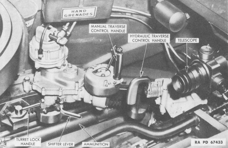
The gunner's controls on an early-production vehicle are shown here. The shifter lever was moved to the up position to engage the hydraulic traversing system, or downward for manual traverse. (Picture from TM 9-755 76-mm Gun Motor Carriage M18 and Armored Utility Vehicle M39.)
Gunner's controls on a late-production vehicle are shown here. Note the repositioned turret lock. (Picture from TM 9-755 76-mm Gun Motor Carriage M18 and Armored Utility Vehicle M39.)
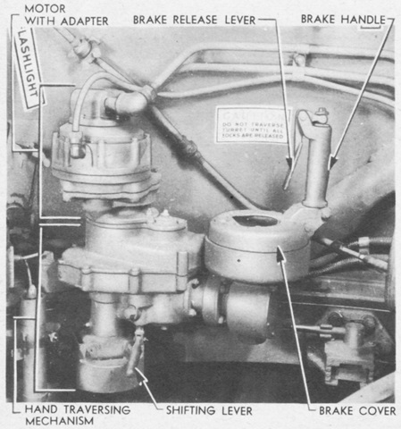
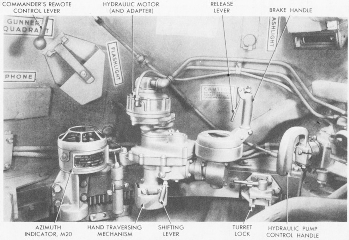
The hand traversing mechanism was engaged by moving the shifting lever to its lower position. When the hand traversing mechanism was engaged and the turret lock was released, a spring-loaded brake held the turret in place until the brake release lever on the brake handle was squeezed. The brake handle was then used as the crank to traverse the turret. (Picture from TM 9-755 76-mm Gun Motor Carriage M18 and Armored Utility Vehicle M39.)
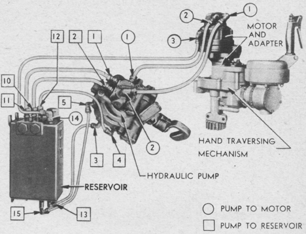
Components and connections of the Oilgear-type hydraulic traverse system are diagrammed in this image. Two oil tubes connected the hydraulic pump and the motor and adapter assembly; one tube supplied pressure to traverse the turret in one direction, and the other tube provided pressure for traverse in the opposite direction. During traverse, oil was returned to the pump via the tube that was not supplying pressure. The capacity of the reservoir was 4 quarts (3.8L) of oil, and it was to be kept ⅔ full. (Picture from TM 9-755 76-mm Gun Motor Carriage M18 and Armored Utility Vehicle M39.)
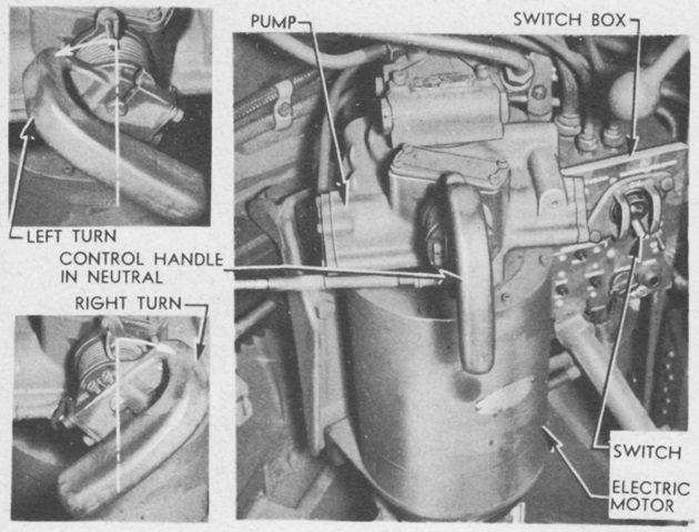
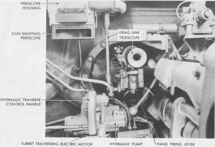
The gunner's control handle regulated the volume and direction of hydraulic oil flow supplied to the hydraulic motor, and therefore as well the speed and direction of turret traverse. Operation of the control handle is detailed here. The turret wiring switch box to the right of the electric motor contained the traverse motor master switch, the firing circuit switch, the firing indicator that glowed when the firing switch was on, a 24-volt outlet socket, and circuit breakers. (Picture from TM 9-755 76-mm Gun Motor Carriage M18 and Armored Utility Vehicle M39.)
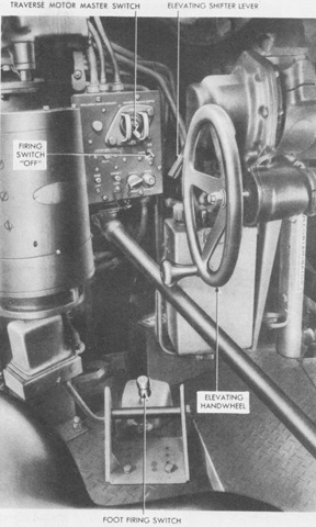
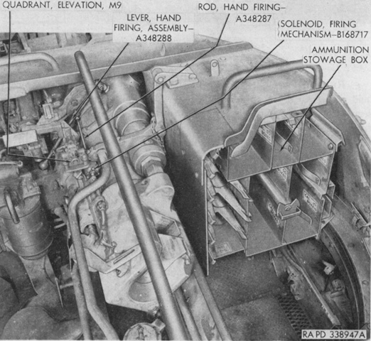
The elevation handwheel and floor firing switch are visible in this image. The elevation gears were engaged by moving the elevation shifter lever to the left. The turret wiring switch box can be seen in front of and to the left of the elevation handwheel. (Picture from TM 9-755 76-mm Gun Motor Carriage M18 and Armored Utility Vehicle M39.)
The position of the gunner's sighting devices are shown here. The telescope M70H, M72C, or M76C was used for direct laying of the 76mm gun; the periscope M4 or M4A1, which contained a 1.44x telescope M47 or M47A2, was used for direct laying against moving targets when firing the 76mm APC projectile M62. (Picture from TM 9-755 76-mm Gun Motor Carriage M18 and Armored Utility Vehicle M39.)
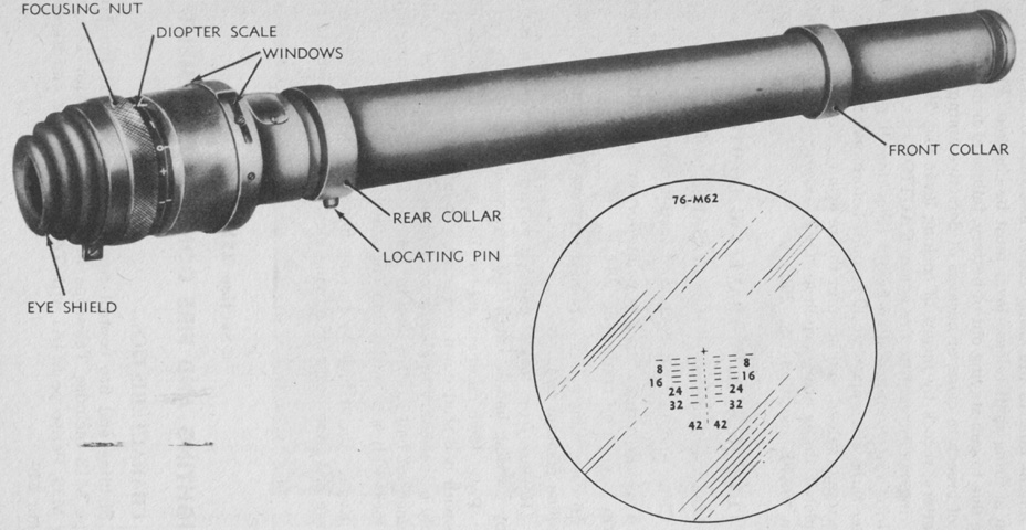
The telescopes M76C and M72C shared the reticle pattern sketched at the lower right. The M76C provided 3x magnification, and its field of view was 21°30'. (Picture from TM 9-755 76-mm Gun Motor Carriage M18 and Armored Utility Vehicle M39.)
The vehicle commander was provided with a remote control lever that connected to the gunner's hydraulic control handle, allowing the commander to traverse the turret as well. (Picture from TM 9-755 76-mm Gun Motor Carriage M18 and Armored Utility Vehicle M39.)
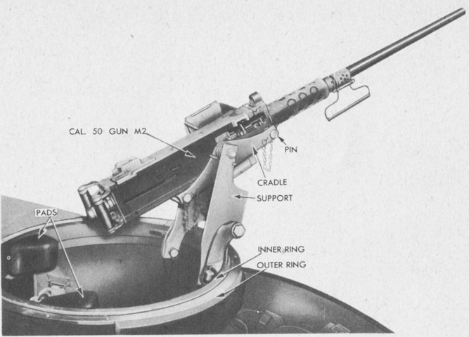
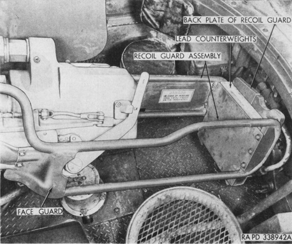
The commander's machine gun mount is detailed here. (Picture from TM 9-755 76-mm Gun Motor Carriage M18 and Armored Utility Vehicle M39.)
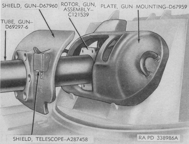
The gun mount M1 consisted of a cradle, two recoil cylinders, a recoil guard, an elevating mechanism, a rotor and mounting plate, and a gun shield. The shield is seen here being separated from the rotor after the six securing screws had been removed. (Picture from TM 9-1308 Ordnance Maintenance--76-mm Guns M1A1C and M1A2; Gun Mount M1 and Combination Gun Mount M62 for Combat Vehicles.)
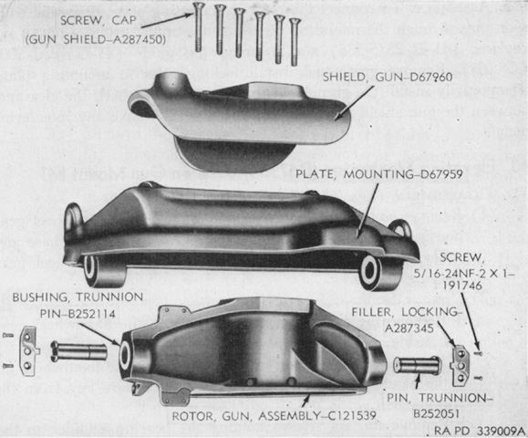
The gun rotor is shown disassembled in this image. (Picture from TM 9-1308 Ordnance Maintenance--76-mm Guns M1A1C and M1A2; Gun Mount M1 and Combination Gun Mount M62 for Combat Vehicles.)
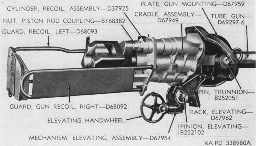
The gun mount M1 is shown here from the right. (Picture from TM 9-1308 Ordnance Maintenance--76-mm Guns M1A1C and M1A2; Gun Mount M1 and Combination Gun Mount M62 for Combat Vehicles.)
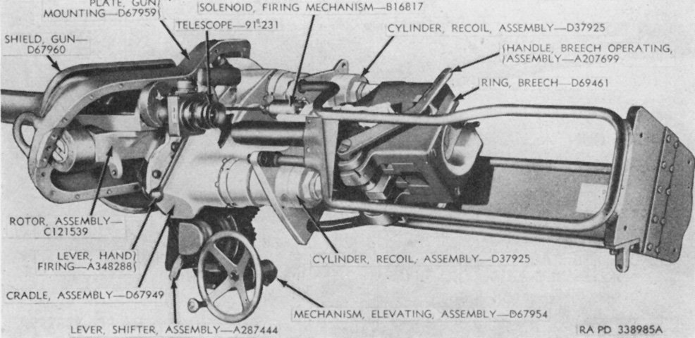
The opposite side of the gun mount M1 is labeled in this image. (Picture from TM 9-1308 Ordnance Maintenance--76-mm Guns M1A1C and M1A2; Gun Mount M1 and Combination Gun Mount M62 for Combat Vehicles.)
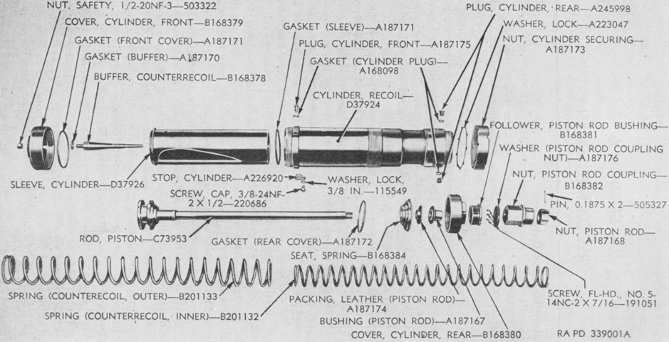
A disassembled recoil cylinder is the subject of this diagram. The recoil system of the gun mount M1 functioned similarly to that of the combination gun mount M62 found in 76mm gun Sherman tanks. (Picture from TM 9-1308 Ordnance Maintenance--76-mm Guns M1A1C and M1A2; Gun Mount M1 and Combination Gun Mount M62 for Combat Vehicles.)
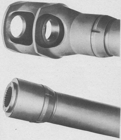
The muzzle brake is mounted in the top image. Below, a thread protecting ring has been installed on a gun lacking a muzzle brake but threaded for one. (Picture from TM 9-755 76-mm Gun Motor Carriage M18 and Armored Utility Vehicle M39.)
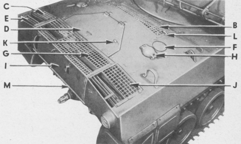
The rear hull deck is labeled here. B. Hull air inlet grille. C. Oil tank filler screen door. D. Hull rear roof door. E. Hull air outlet grille left. F. Fuel tank gage cover. G. Hull air outlet grille center. H. Fuel tank cap cover. I. Hull rear upper plate. J. Hull air outlet grille right. K. Oil filter handle. L. Drain valve handle. M. Hull rear door. (Picture from TM 9-755 76-mm Gun Motor Carriage M18 and Armored Utility Vehicle M39.)
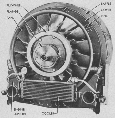
M18s serial numbers 1 to 1350 were powered by the R-975-C1 engine that made 350 brake horsepower at 2,400rpm. The engine was 45" (114cm) in overall diameter and weighed 1,400lb (635kg). (Picture from TM 9-755 76-mm Gun Motor Carriage M18 and Armored Utility Vehicle M39.)
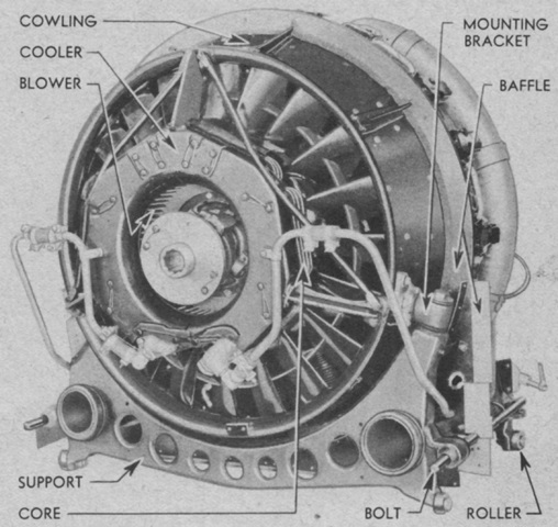
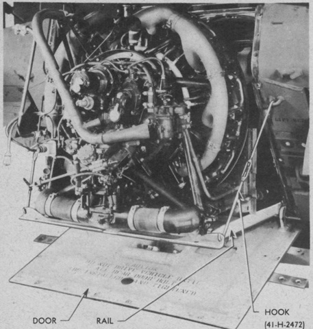
M18s with serial numbers above 1350 used the R-975-C4. The two engines used different oil coolers and connecting oil and fuel pipes, meaning they were not interchangeable. A replacement engine, therefore, needed to match the one with which the motor carriage was originally manufactured. The -C4 produced 400 brake horsepower at 2,400rpm, and weighed 1,505lb (682.7kg). Note the rollers on the engine support; these allowed the engine to be easily pulled out from the hull on a set of rails. (Picture from TM 9-755 76-mm Gun Motor Carriage M18 and Armored Utility Vehicle M39.)
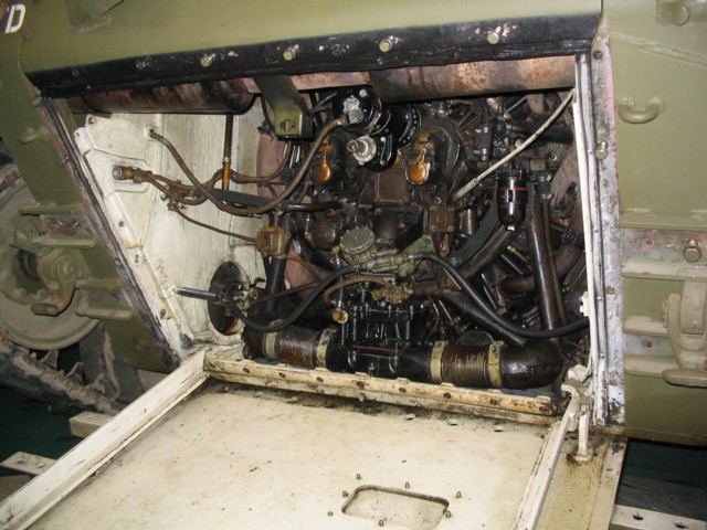
The rear hull door has been lowered after the reinforcement rails have been removed. The engine's exhaust manifold and mufflers are among the components visible.
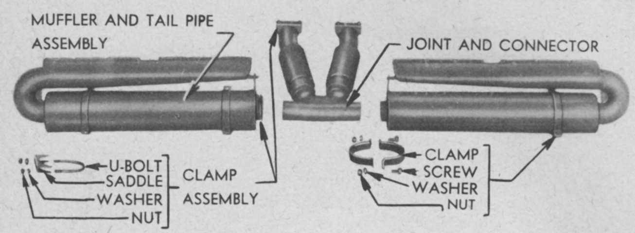
The disassembled muffler and tail pipe assemblies are isolated in this image. Engine exhaust was directed upward through the rear hull roof grille. (Picture from TM 9-755 76-mm Gun Motor Carriage M18 and Armored Utility Vehicle M39.)
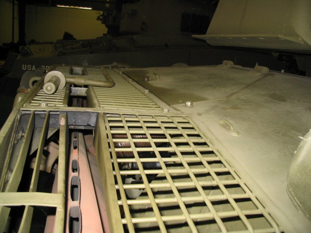
The engine exhaust outlets are visible here pointing upward from the light-colored tail pipes.
The engine removal rails are in use in this picture. On some vehicles, like the one here, the rear hull door could be unbolted from the rails and lowered further to allow access to the bottom of the engine. (Picture from TM 9-755 76-mm Gun Motor Carriage M18 and Armored Utility Vehicle M39.)
The rear transfer case transmitted power from the engine to the propeller shaft under the hull floor. The shifter lever actuated a sliding clutch that could disengage the transfer case so that no power would be transmitted to the powertrain. (Picture from TM 9-755 76-mm Gun Motor Carriage M18 and Armored Utility Vehicle M39.)
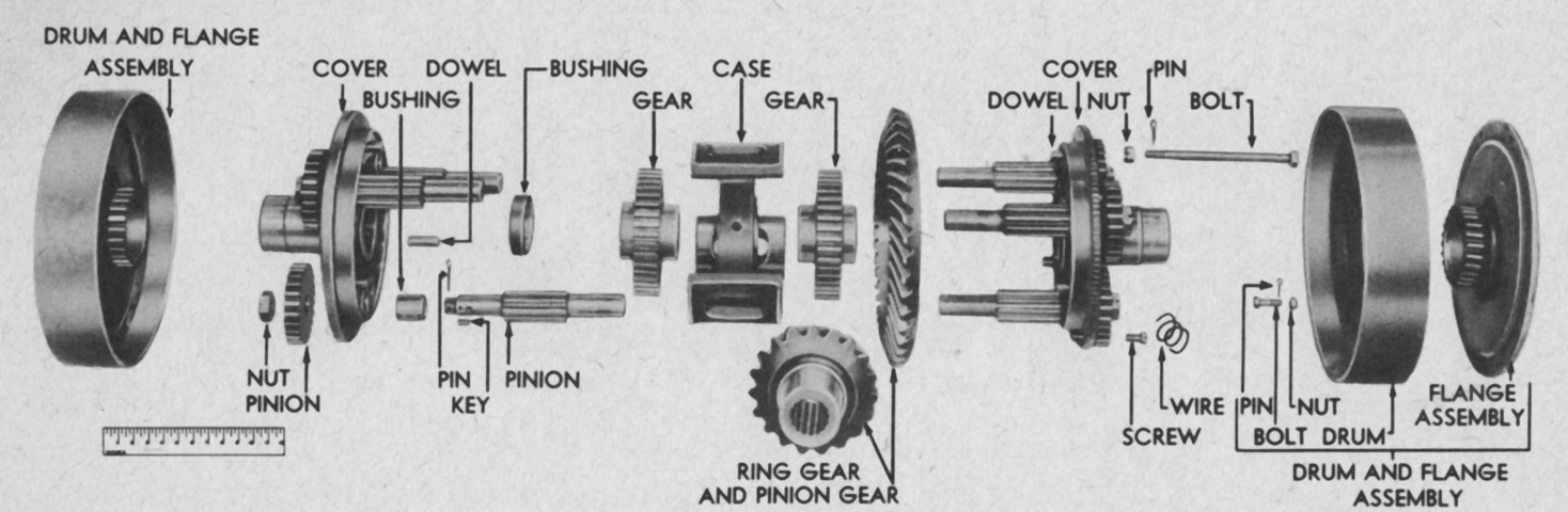
The rear transfer case is shown here disassembled into its constituent parts. (Picture from TM 9-1755A Ordnance Maintenance--Power Train for 76-mm Gun Motor Carriage T70.)
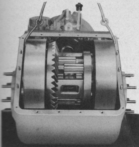
The front transfer case, transmission, and differential are shown connected here. The Torqmatic transmission assembly was a manually controlled, hydraulically operated unit that prevented engine stalling under heavy loads and automatically varied the torque applied to the driving sprockets according to operating requirements while the engine was held near its most efficient speed. The transfer case accepted power from the lowered propeller shaft and transmitted it to the torque converter which was physically higher. The torque converter could increase engine torque by around 4.5x during heavy loading and low engine speeds. The transmission weighed 1,347lb (611.0kg) dry, and when combined with the differential assembly weighed 2,512lb (1,139kg) dry. (Picture from TM 9-755 76-mm Gun Motor Carriage M18 and Armored Utility Vehicle M39.)
The front transfer case is seen in this exploded view. A. Input shaft oil seal. B. Drive gear outer bearing retainer. C. Drive gear bearing retainer gasket. D. Idler gear outer bearing retainer. E. Idler gear bearing retainer. F. Input shaft. G. Idler gear retainer ring. H. Drive gear outer bearing. I. Idler gear outer bearing. J. Transfer case cover. K. Drive gear. L. Idler gear. M. Drive gear inner bearing. N. Input shaft nut washer. O. Input shaft nut. P. Drive gear inner bearing race. Q. Idler gear inner bearing. R. Transfer case cover gasket. S. Transfer case. T. Turbine front rotor shaft. U. Oil pump seal ring. V. Driven gear. W. Driven gear bearing. X. Front rotor nut lock washer. Y. Turbine front rotor nut. Z. Driven gear bearing retainer gasket. AA. Driven gear bearing retainer. (Picture from TM 9-1755A Ordnance Maintenance--Power Train for 76-mm Gun Motor Carriage T70.)
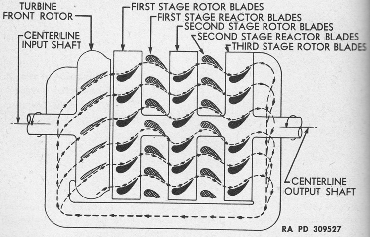
The torque converter delivered more torque from its output shaft than was supplied to its input shaft, but at a lower speed. Engine power was absorbed at the input side at a relatively constant speed and converted into hydraulic pressure by the turbine front rotor. This pressure transmitted the engine power to the output shaft through the rear rotor as high torque at low output shaft speed; no direct mechanical connection existed. At idle, the torque converter transmitted almost no power to the output shaft, which allowed it to function as an automatic clutch. This simplified schematic shows the operation of the torque converter, with the angles of the blades illustrated. The turbine front rotor forced oil outwards into the first stage rotor blades, which absorbed energy from the oil and reversed its direction. This action was repeated twice more until essentially all the energy from the oil was captured. (Picture from TM 9-1755A Ordnance Maintenance--Power Train for 76-mm Gun Motor Carriage T70.)
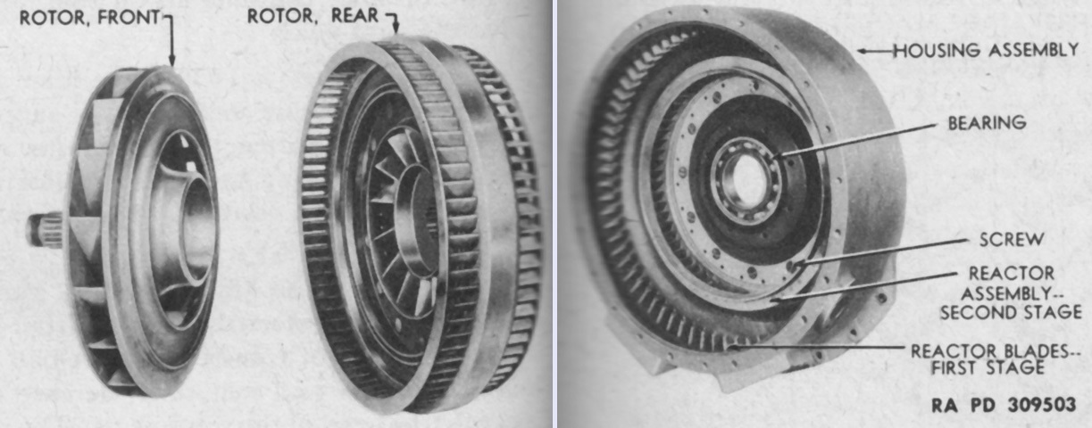
Major components of the torque converter are shown in these images, with the turbine front and rear rotors on the left and the turbine housing on the right. The front rotor was actually engulfed by the rear rotor when assembled, and the flow of oil through the front rotor's blades into those of the rear rotor can be gleaned. The turbine housing featured two stationary sets of reactor blades that directed the oil flow through the second and third stage rotor blades on the rear rotor. (Picture from TM 9-1755A Ordnance Maintenance--Power Train for 76-mm Gun Motor Carriage T70.)
An exploded view of the internal parts of the differential is provided in this image. (Picture from TM 9-1755A Ordnance Maintenance--Power Train for 76-mm Gun Motor Carriage T70.)
The differential assembly is shown assembled while being removed from its carrier. (Picture from TM 9-1755A Ordnance Maintenance--Power Train for 76-mm Gun Motor Carriage T70.)
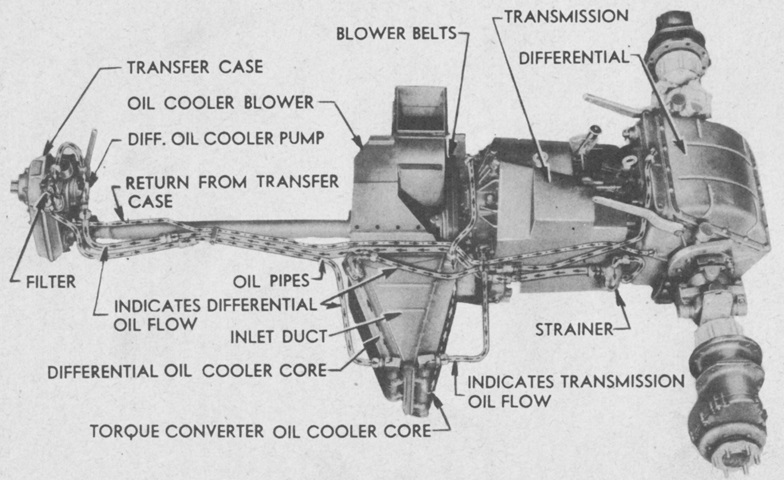
The assembled powertrain, from the rear transfer case to the final drives, is shown in this diagram of its lubrication components. (Picture from TM 9-755 76-mm Gun Motor Carriage M18 and Armored Utility Vehicle M39.)
Similarly to the engine, the transmission assembly was able to be removed from the front of the vehicle after the front cover was dismounted and a rail system was assembled and installed. (Picture from TM 9-755 76-mm Gun Motor Carriage M18 and Armored Utility Vehicle M39.)
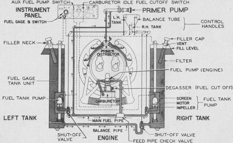
The fuel system is diagrammed in this sketch. (Picture from TM 9-755 76-mm Gun Motor Carriage M18 and Armored Utility Vehicle M39.)
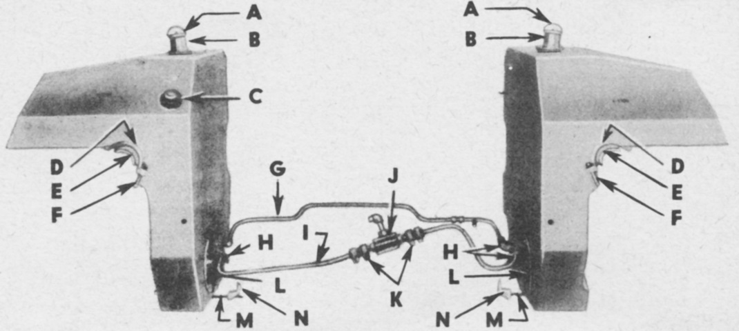
A fuel tank was mounted in the hull on each side of the engine compartment, extending into the side sponsons. The left tank had a capacity of 75gal (280L), while the right held 90gal (340L). The left fuel tank also incorporated a compartment for the requisite 11gal (42L) of engine oil. The tanks were filled separately via their own fillers, and they each had a fuel gage that could be selected at the driver's instrument panel. A. Filler cap (fuel). B. Filler neck. C. Filler cap (oil). D. Support strap. E. Spacer. F. Tee bolt. G. Balance pipe. H. Fuel shut-off valve. I. Fuel pipe. J. Check valve. K. Hose. L. Tank pump cover. M. Anchor bolt. N. Anchor bolt clip. (Picture from TM 9-755 76-mm Gun Motor Carriage M18 and Armored Utility Vehicle M39.)
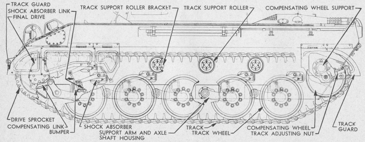
Details of the suspension are illustrated in this image. Note the compensating link attached to the drive sprocket, the purpose of which is detailed below. (Picture from TM 9-755 76-mm Gun Motor Carriage M18 and Armored Utility Vehicle M39.)
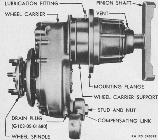
The drive sprocket, wheel spindle, final drive gear, pinion, and pinion shaft were all assembled in a wheel carrier supported by ball bearings that was able to swing the sprocket forwards and backwards as the front track wheel rose and fell, helping to compensate for varying track tension as the vehicle tackled terrain. This compensating link also had a shock absorber attached. (Picture from TM 9-755 76-mm Gun Motor Carriage M18 and Armored Utility Vehicle M39.)
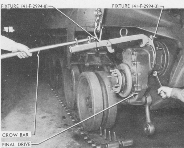
The drive sprocket and compensating link have been detached, and the final drive is being removed in this image. Later-production machines, like the one pictured, could use four evenly-spaced bolts to push the final drive out of the hull side plate. Early-production motor carriages could require the use of a jack inside the hull to force the final drives out. The reduction ratio for the final drives was 2.175:1. (Picture from TM 9-755 76-mm Gun Motor Carriage M18 and Armored Utility Vehicle M39.)
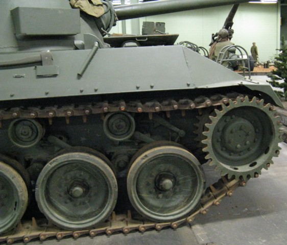
This vehicle is fitted with the original M18-type drive sprocket and single-pin track. Note that the track is engaged by every other sprocket tooth.
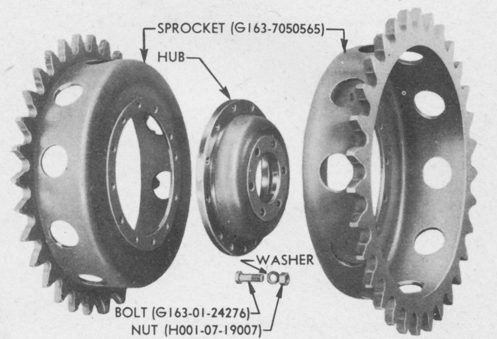
An exploded view of a drive sprocket is shown in this image. (Picture from TM 9-755 76-mm Gun Motor Carriage M18 and Armored Utility Vehicle M39.)
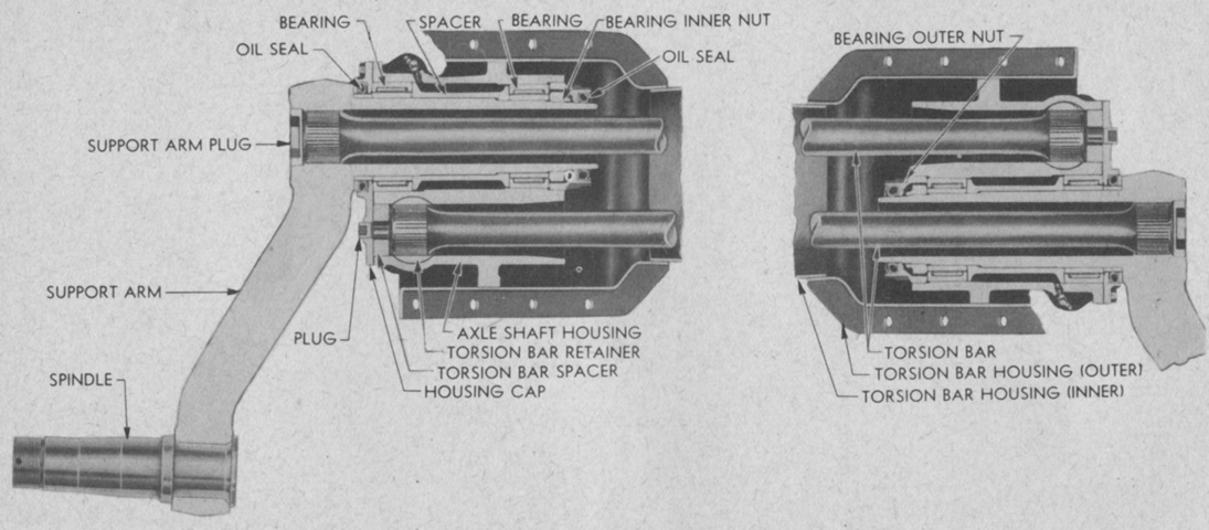
This sectional view shows the road wheel support arms, housings, and torsion bars. As seen, the wheels on opposite sides were slightly offset due to the torsion bars reaching across the entirety of the hull's width. (Picture from TM 9-755 76-mm Gun Motor Carriage M18 and Armored Utility Vehicle M39.)
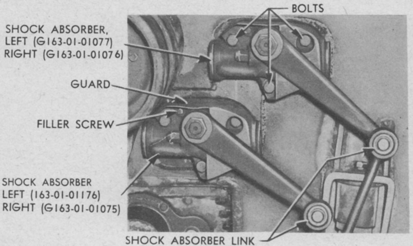
The shock absorbers were heavy-duty double-acting units, and were protected by guards. (Picture from TM 9-755 76-mm Gun Motor Carriage M18 and Armored Utility Vehicle M39.)
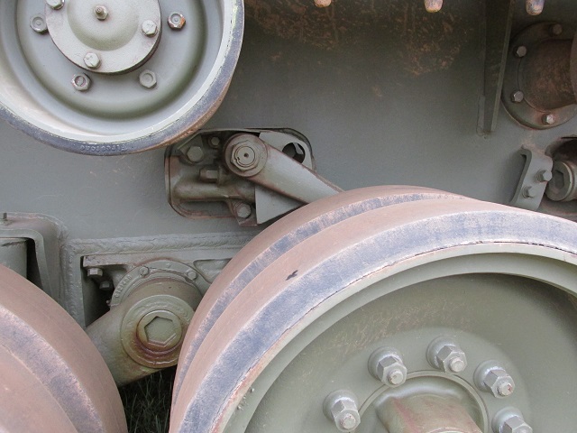
One of the shock absorbers is centered in this image. Also visible are a return roller mount to the upper right and one of the track wheel support arms to the lower left.
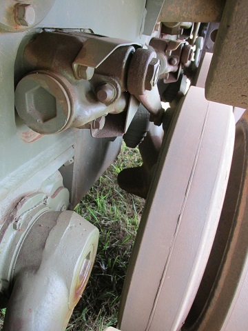
A view from behind the same shock absorber is provided here.
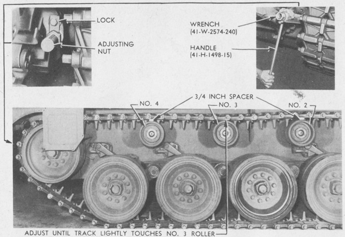
Track tension was adjusted by moving the compensating idlers via the adjusting nut until the track touched the tires of the number 3 support roller with pressure light enough that the roller could still be turned by hand. (Picture from TM 9-755 76-mm Gun Motor Carriage M18 and Armored Utility Vehicle M39.)
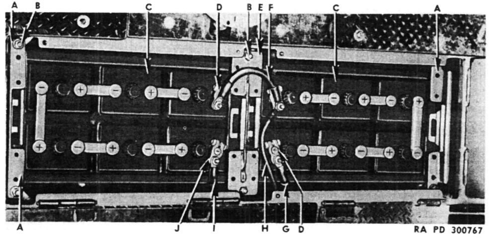
Two 12-volt, 168 ampere hour, 6-cell storage batteries were housed under the the subfloor to the left of the turret slipring. They were connected to provide single-wire with ground-return circuits of both 12 and 24 volts. A. Clamp, assembly. B. Nut/washer. C. Battery. D. Terminal. E. Clamp, assembly. F. Cable, assembly. G. Cable, assembly. H. Cable, assembly. I. Cable, assembly. J. Terminal. (Picture from ORD 7-8-9 SNL G-163.)
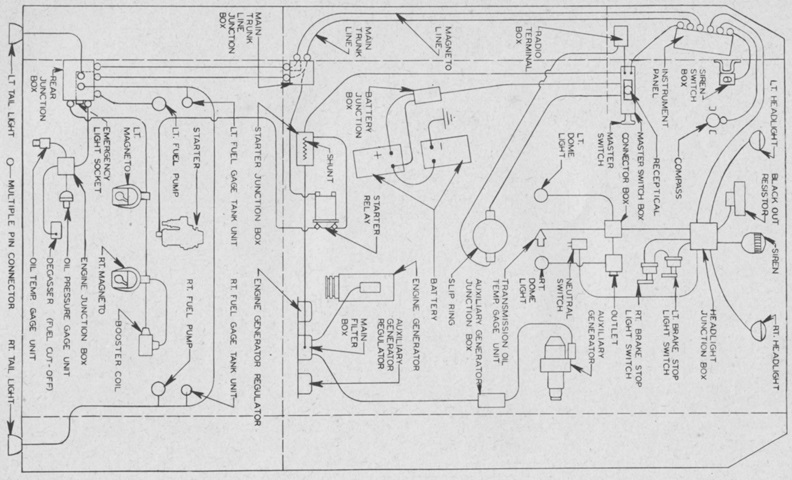
This schematic of electrical components reveals the location of installations including the batteries and the auxiliary generator. (Picture from TM 9-755 76-mm Gun Motor Carriage M18 and Armored Utility Vehicle M39.)
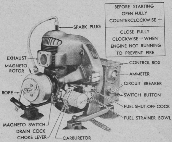
The Homelite HRUH-28 auxiliary generator and engine was powered by a single-cylinder, air-cooled, 2-cycle gasoline engine. Its generator produced 1,500 watts, 30 volts direct current. The engine was fed from its own 5gal (19L) fuel/oil tank. (Picture from TM 9-755 76-mm Gun Motor Carriage M18 and Armored Utility Vehicle M39.)
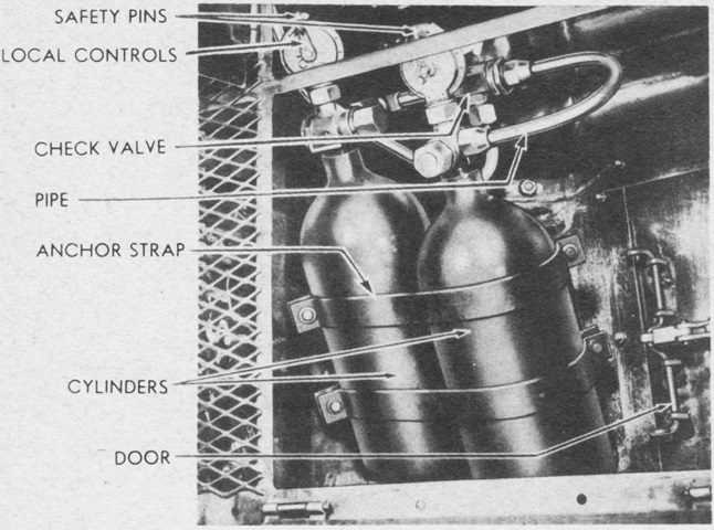
The fixed fire extinguisher system consisted of two 10lb (4.5kg) CO2 cylinders routed to six discharge horns in the engine compartment. The cylinders were located under the right rear subfloor door, and they could be actuated by two sets of remote control handles, on the right front of the hull roof and on the hull wall behind the assistant driver's seat. Each handle in each location discharged a single cylinder, and the cylinders could also be actuated by raising the right rear subfloor door over the cylinders and moving the lever on the local control. In addition, a portable fire extinguisher was stowed in the sponson beside the assistant driver. (Picture from TM 9-755 76-mm Gun Motor Carriage M18 and Armored Utility Vehicle M39.)
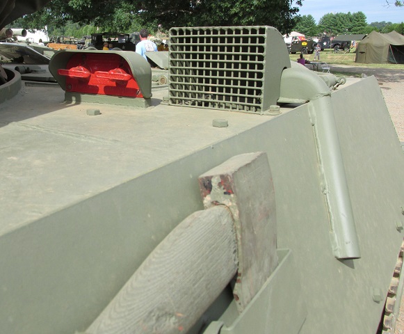
Directly behind the assistant driver's hatch is the air outlet for the auxiliary generator engine, and its downward-pointing exhaust pipe is welded to the outer sponson. The red control handles for the fixed fire extinguishers can also be seen in this image.
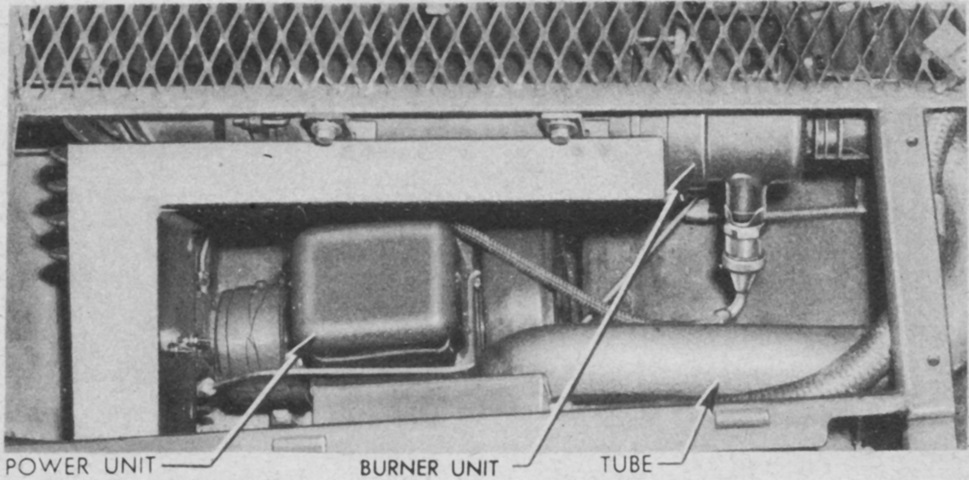
Vehicles with serial numbers 1701 and above were fitted from the factory with winterization equipment components, except for the heater power and burner units, connecting air tube, fuel pipes, and air intake shutters. These were to be installed in the field, and are illustrated here. When installed, fuel from the engine fuel pump was discharged through an atomizing nozzle into the burner unit, and the resulting fuel-air mixture was ignited by an electrode located in front of the nozzle. The heat produced was blown from the burner into hot air distribution tubes that reached to the transmission and differential, transmission and differential oil cooler cores, vehicle batteries, auxiliary generator, and the rear of the engine. A valve only allowed the heat to reach either the front or the rear of the vehicle; this valve needed to be turned for the opposite end to be heated. (Picture from TM 9-755 76-mm Gun Motor Carriage M18 and Armored Utility Vehicle M39.)
