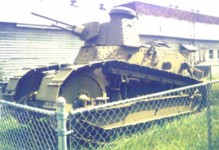
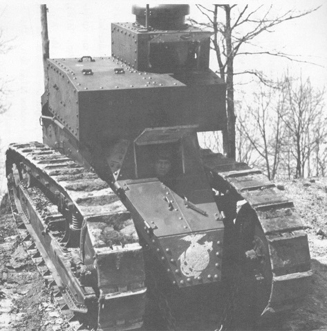
Six-ton Tank M1917 in Nitro, West Virginia.
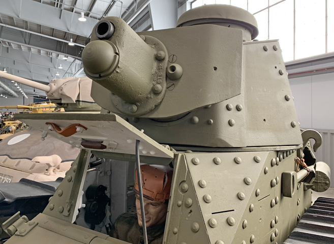
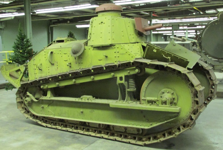
Like all M1917s, this little vehicle is crowned by a flat-plated octagonal turret. The commander was provided with a cupola, or tower as it was called at the time, with three vision slits for rudimentary visibility. The cupola cover could not be opened all the way due to a stop on the rear of the cover. Entry for the commander was through two hatches in the rear of the turret. The large weapon is a replica, apparently of the 8mm Hotchkiss machine gun fitted to French FTs, but the gun mount appears to be a late-production one for the 37mm gun. The US machine gun mounts provided barrel shrouds, and consequently the barrels could not be seen. The anti-ditching tailpiece is visible, and an engine muffler would normally be installed between the two vertical mounts on the hull side. On French FTs, the engine muffler was on the opposite side of the hull.
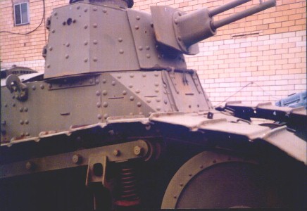
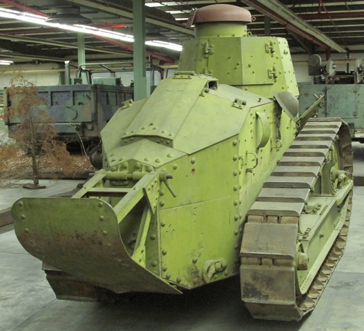
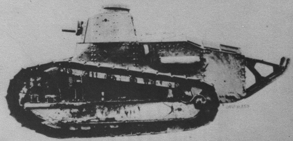
This view illustrates one of the extra driver's vision slots placed in the triangular armor plates in the American version of the FT. The circular hole in the turret is a pistol port, or loophole as they were known.
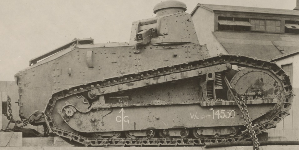
This tank, tied down on a transporter, is armed with the 37mm gun in an early-production mount. (Picture available from the National Archives.)
The later 37mm gun mount can be seen on this tank, which was taking part in a mock battle for graduates of the Army War College. The large aperture on the gun shield's left side was for the sighting telescope. (Picture taken 12 May 1925 by Harris & Ewing, Inc.; available from the Library of Congress.)
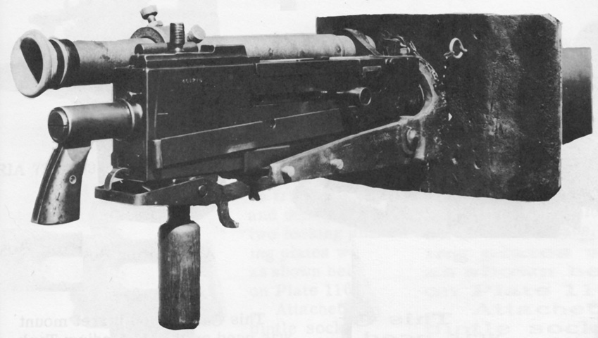
A closer look at the later 37mm gun mount is provided in this image.
The later 37mm gun mount is seen here in profile. A short-handled shovel is stowed on the left side of the hull. (Picture from TR 1325-A Tanks: Six-ton Tank, M1917.)
These tanks are armed with the Marlin machine gun. The near machine has a mud-covered 10-ton (9,100kg) jack stowed on the suspension girder. (Picture taken 24 May 1919; available from the National Archives.)
A closer view of the stowed jack is provided in this picture.
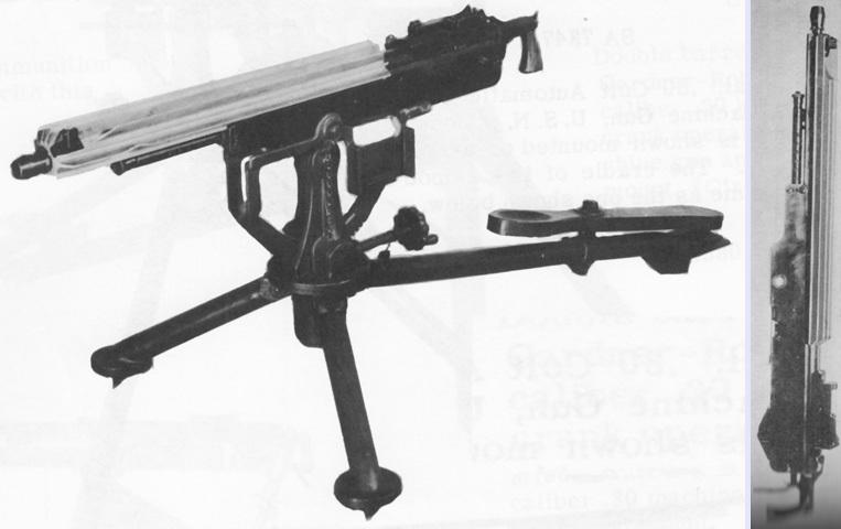
The Marlin tank machine gun is seen on an M1895 Colt tripod mount on the left and dismounted on the right. (Pictures from Weapon Mounts for Secondary Armament and Handbook of Ordnance Data.)
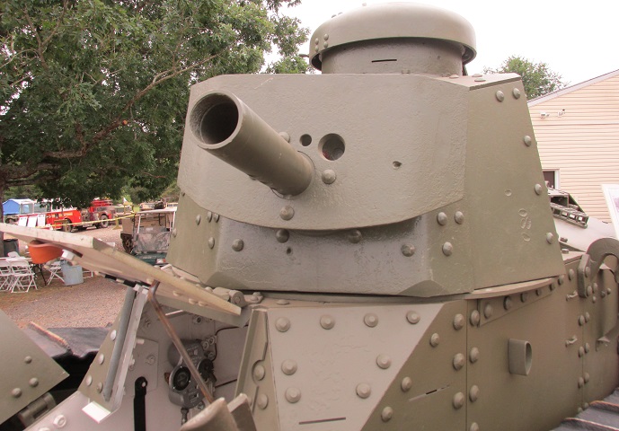
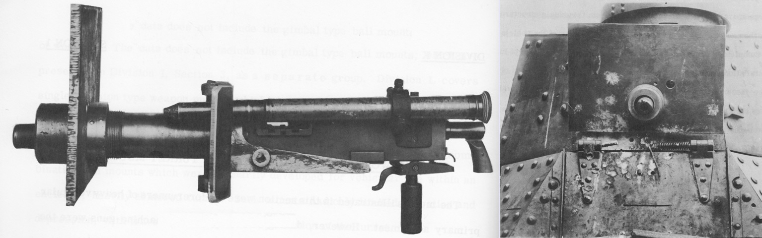
The gun shield and mount on this tank are representative of the ball mount fitted for the Browning tank machine gun, which can be contrasted with the Marlin-armed vehicles above.
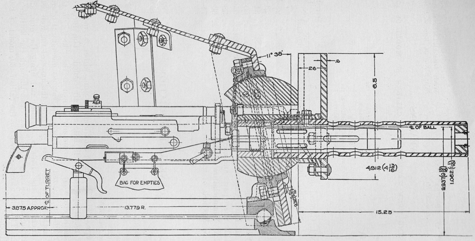
The Browning tank machine gun is installed in its ball mount in this diagram. The gun weighed 35lb (16kg) with its jacket, and had a rate of fire of 400-550 rounds/min. Maximum chamber pressure was 53,000psi (3,700kg/cm²), and theoretical muzzle velocity was 2,700 feet/sec (820m/s). (Picture from TR 1320-39 C1.)
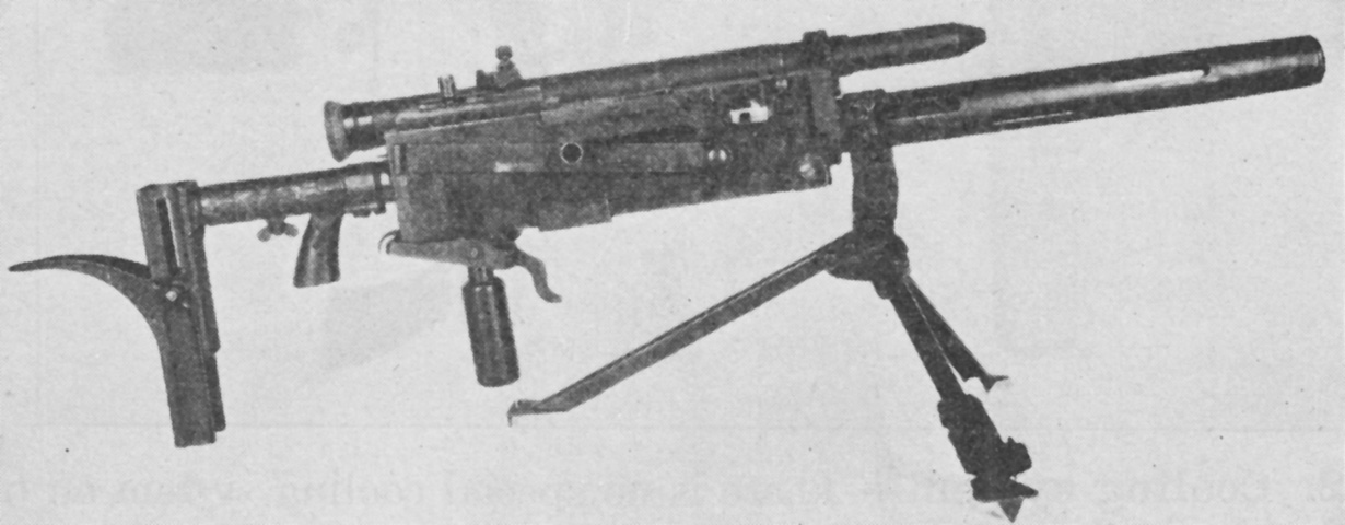
When dismounted from the tank, the Browning could be equipped with an adjustable shoulder rest and used with the emergency tripod Mk. I. The telescopic sight was the same as that used with the 37mm gun M1916. (Picture from TR 1320-39 C1.)
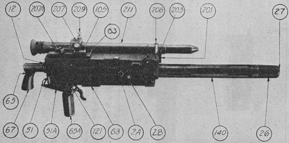
The Browning tank machine gun is seen from the right. 12. Rod, driving spring. 207A. Sight, rear. 207. Bracket, rear telescopic sight. 209. Screw, rear telescopic sight bracket adjusting. 105. Latch. 83. Plate, cover. 211. Sight, telescopic. 206. Bracket, front telescopic sight. 203. Blade, front sight. 201. Bracket, front sight. 27. Plug, muzzle attachment. 26. Attachment, muzzle. 140. Jacket, barrel. 2B. Rivet, bolt latch. 2A. Latch, bolt. 63. Stirrup. 121. Bracket, elevating. 65A. Grip, lower. 51A. Trigger, auxiliary. 51. Trigger. 67. Stock, right. 65. Grip. (Picture from TR 1320-39 C1.)
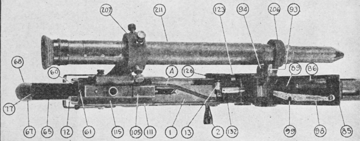
The Browning is shown from above with the cover raised and the bolt in the forward position. 68. Stock, left. 60. Back plate. 207. Rear telescopic sight bracket. 211. Telescopic sight. A. Belt feed cover cam groove. 126. Belt holding pawl split pin. 123. Belt holding pawl. 94. Belt feed pawl. 206. Front telescopic sight bracket. 93. Belt feed slide. 89. Cover extractor spring. 86. Cover extractor cam. 85. Cover. 98. Belt feed lever. 99. Belt feed lever pivot. 132. Cartridge stop, rear. 2. Bolt handle. 13. Extractor. 1. Bolt. 111. Side plate, right. 105. Latch. 115. Top plate. 61. Latch stop screw. 12. Driving spring rod. 65. Grip. 67. Stock, right. 77. Adjusting screw. (Picture from TR 1320-39 C1.)
During the switchover from the Marlin to the Browning machine guns, Marlin mounts were modified to accept the Browning until sufficient purpose-designed Browning mounts were available, and such a mount is shown isolated on the left and installed in the tank on the right. Note the secondary grip and trigger under the gun. (Picture from Weapon Mounts for Secondary Armament.)
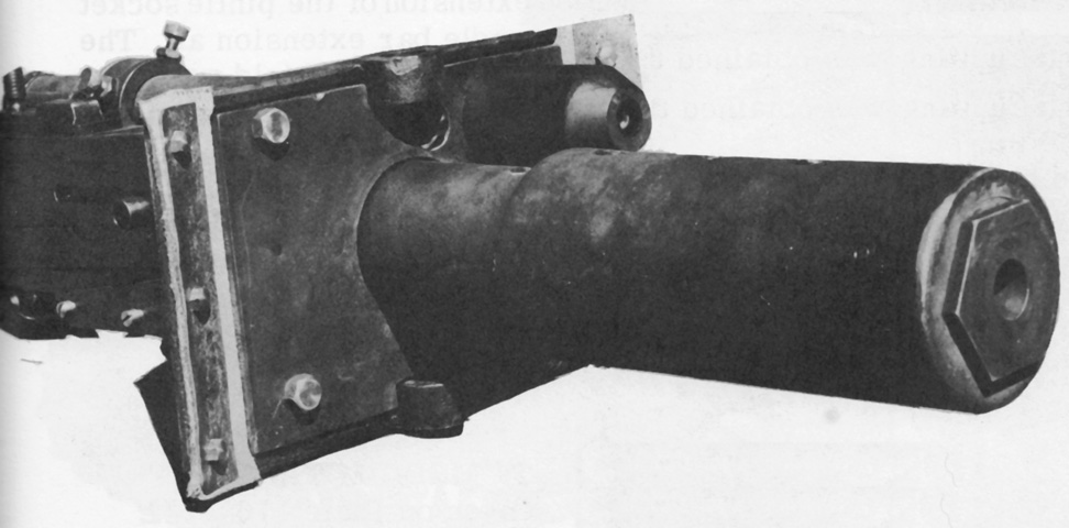
A second modification to the Marlin gimbal mount to fit the Browning machine gun is shown in this picture. Armored jackets protected the gun barrel and telescope. (Picture from Weapon Mounts for Secondary Armament.)
The above mount is seen from the rear. (Picture from Weapon Mounts for Secondary Armament.)
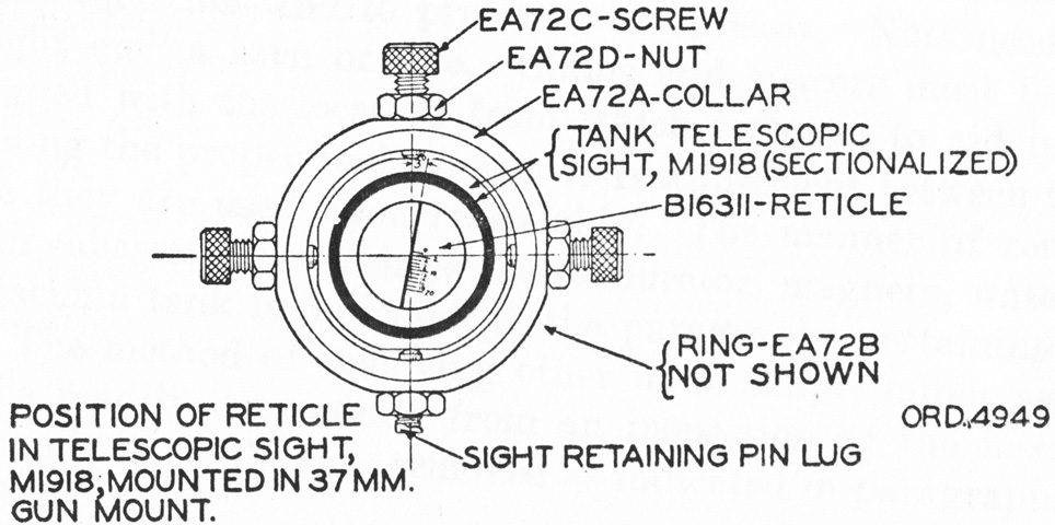
A view down the telescopic sight reveals the positioning of the reticle. It was graduated for Mark II high-explosive ammunition, and provided magnification of 1-1.05 diameters. (Picture from TR 1325-A Tanks: Six-ton Tank, M1917.)
This Browning machine-gun armed tank shows the placement of a long-handled shovel and mattock on the hull side, paulin on the tailpiece, and spare track links on the suspension girder. (Picture from TR 1325-A Tanks: Six-ton Tank, M1917.)
A line composed of both 37mm gun and Browning machine gun tanks of the 1st and 2d Tank Regiments was awaiting inspection. Stowage on the right side is better seen in this clearer image, except for the spare track, which is covered in dirt. (Picture taken 29 August 1930; available from the National Archives.)
The gun mount appears to be for the Browning M1919 machine gun. Tool stowage loops are present along the vehicle's side, a long shovel on top and a mattock below.
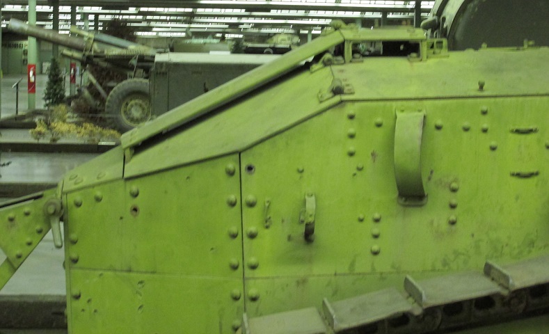
The doors in the turret rear can be seen, as well as the engine compartment air intake and details of the attachment of the tailpiece. The tailpiece was originally rectangular in shape, but the corners were rounded off once service use showed that the 90° corners were a danger with the tank in motion.
The tailpiece has not been fitted to this machine, but the engine muffler is mounted. Stowage for a shorter shovel can be seen forward of the muffler. With the tailpiece removed, it is easier to see the attachment shaft for the hand crank to start the engine.
The engine hand crank is attached here.
The engine compartment was fed air through this raised louvre arrangement. Hinges that allowed access to the engine compartment can also be seen.
The engine compartment hinges are in use here. The rear middle door opened to an almost horizontal position, and the right and left rear doors were able to be opened just past vertical once the middle door was fully opened. (Picture from TR 1325-A Tanks: Six-ton Tank, M1917.)
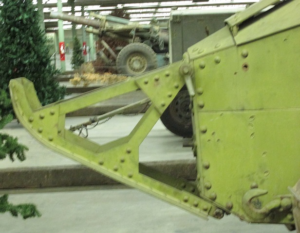
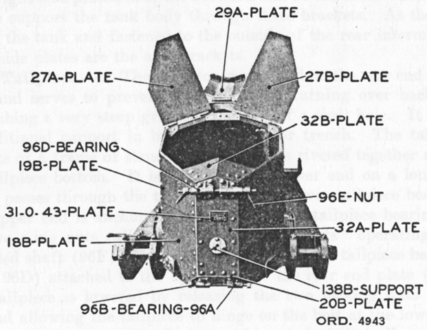
Details of the attachment of the tailpiece are shown in this image, including the handle that screws onto the top threaded rod.
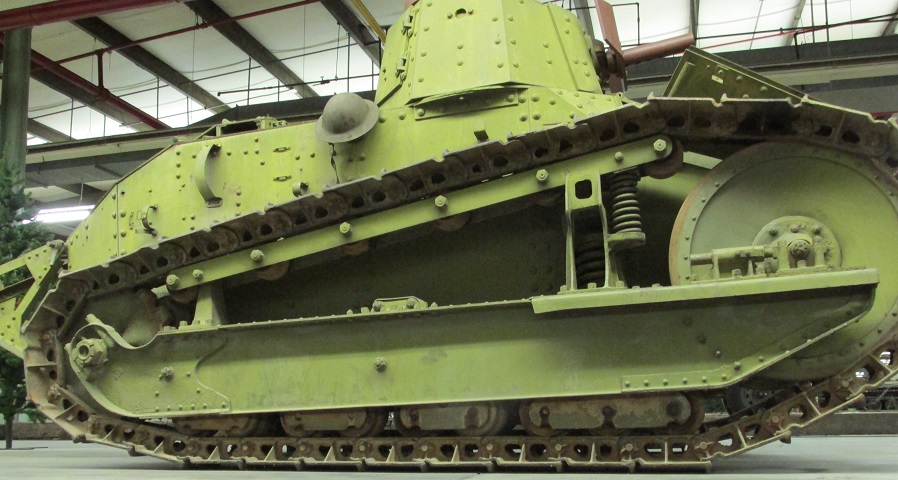
The vehicle's suspension is highlighted here. The front bogie (or "truck") had 3 rollers in front and two in the rear, while the rear bogie had two bogies in each position. The springing of the return roller bracket and the return rollers themselves can be seen.
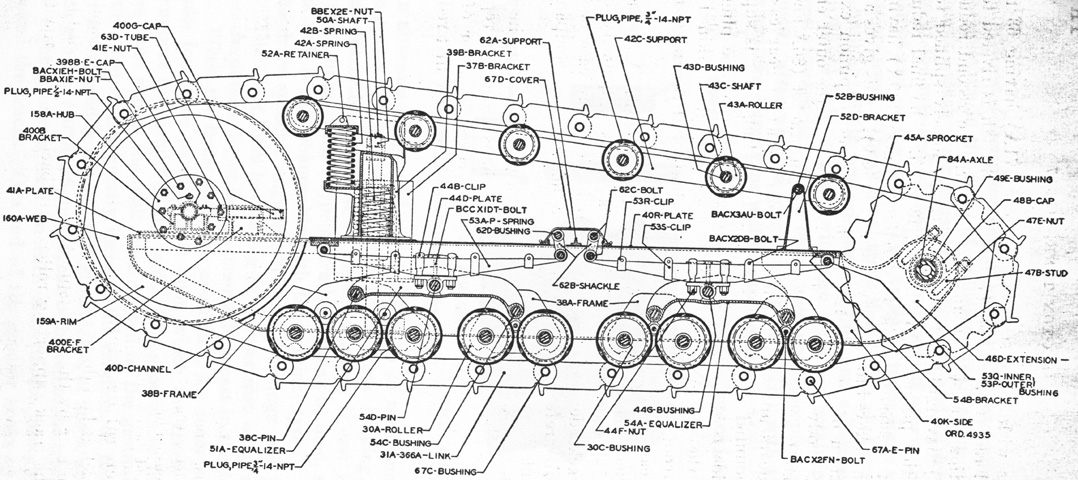
The suspension is diagrammed with the track frame ghosted. The position and attachment of the leaf springs are visible. (Picture from TR 1325-A Tanks: Six-ton Tank, M1917.)
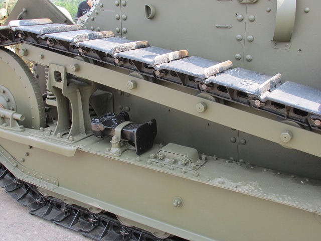
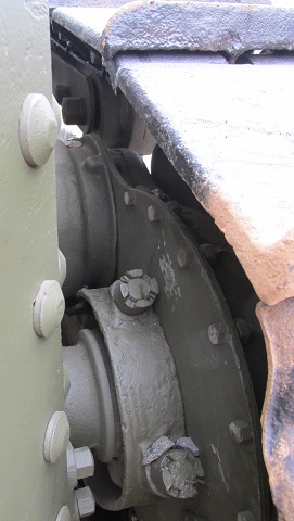
Details of the sprocket wheel and tracks are shown here.
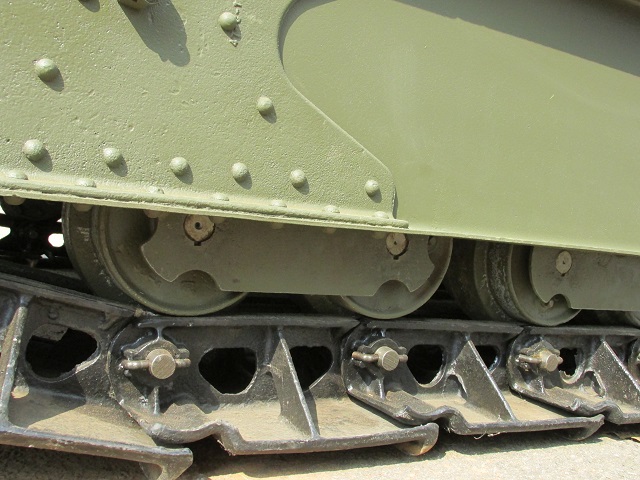
The wheels on the tank have a center flange that rides in the channel created by the track link rails.
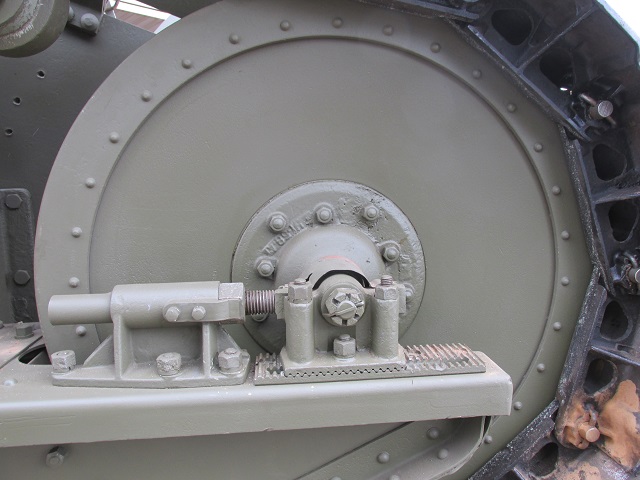
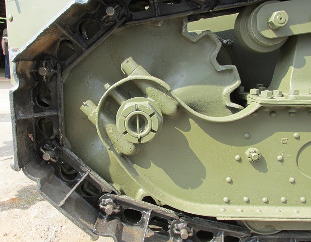
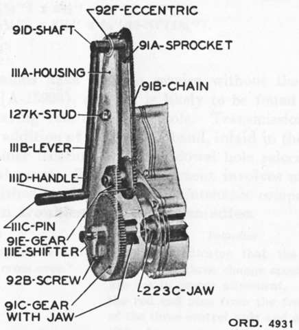
The mechanism for moving the large idler wheel forwards or backwards to adjust the track tension is shown here. Unlike the French FT on which the design was based, the US tank used an all-steel idler wheel and an adjustment screw for each side of the wheel.
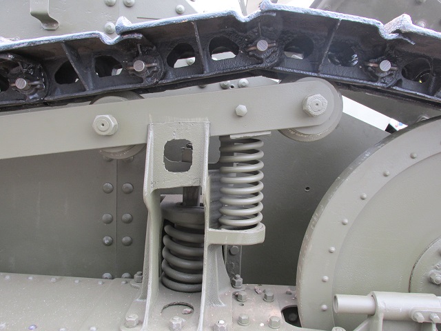
The return rollers were mounted on a frame that was pivoted at the rear and sprung on the front, allowing the long-pitch tracks to compress the springs as they moved over the front roller.
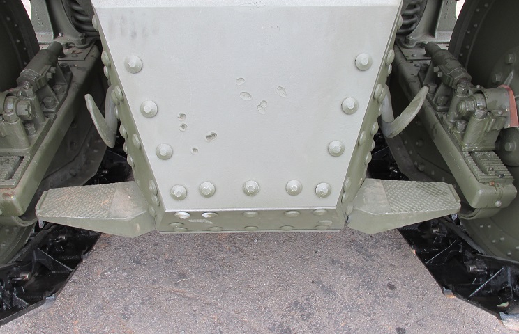
The driver was provided with steps on each side of the tank's nose. The suspension frame pivoted around the rear axle and was sprung at the front by a large coil spring.
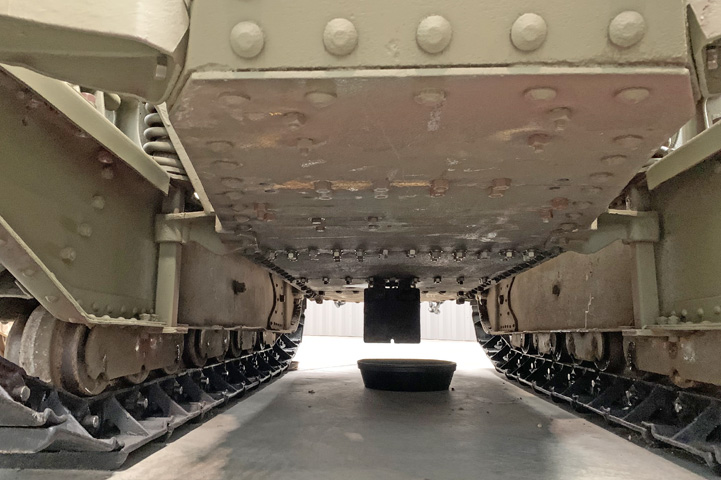
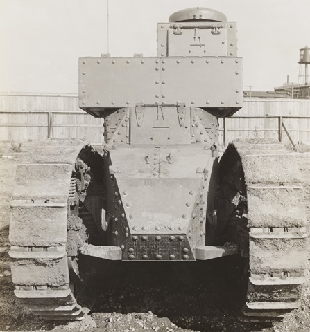
The hull underside is seen here from the front.
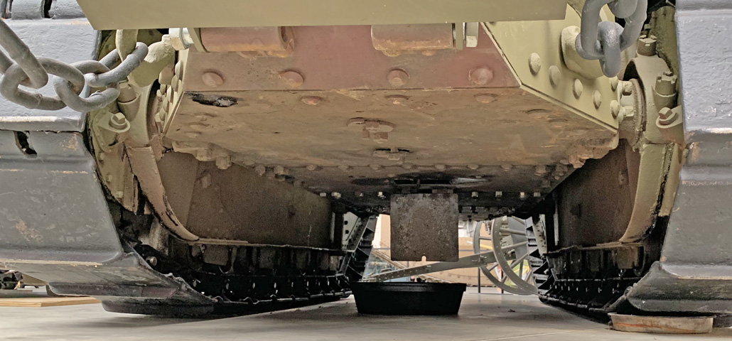
The rear hull underside is shown in this image.
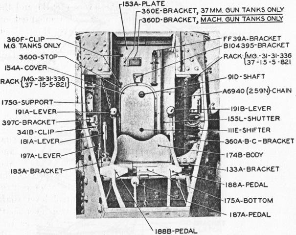
The hull interior is shown from the front with the upper nose plate and driver's tool box removed for clarity. The brake pedal was on the driver's right, the clutch was on the left, and the accelerator pedal was between these, contrary to modern placement. (Picture from TR 1325-A Tanks: Six-ton Tank, M1917.)
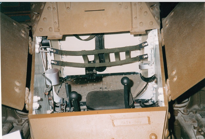
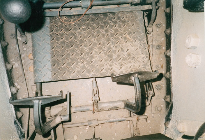
Two of the driver's doors are open on this model; the front plate with the forward vision slit could also be swung up to gain access to the tank. The driver's seat was elevated about 6" (15cm) above the tank's floor, and the black webbing slung across the hull served as a backrest for the driver. The steering levers, topped by round black knobs, are visible. When parked, the steering levers were secured by chains hung on the sides of the driver's compartment. The gearshift lever is visible just outboard of the right-hand steering lever. Visible on the rear bulkhead is the interior starting crank for the engine.
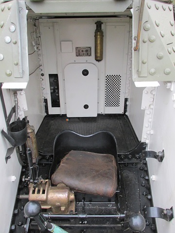
The front flap is raised on this machine. The gearshift lever can be seen to the driver's right. On the engine compartment bulkhead, the larger upper hole for the interior engine crank was for the handle attachment, and the lower smaller hole was for the engaging plunger. Two gold-colored fire extinguishers are visible, one to the driver's right below the instrument panel and on just left of the fire screen's centerline. In service, these would have been 1 quart (1L) Pyrene extinguishers.
This view illustrates more of the driver's controls. The pedal on the driver's left is the clutch, while the brake pedal is on his right. The accelerator pedal is on the linkage forward of the brake and clutch pedals, and just appears at the bottom of the frame.
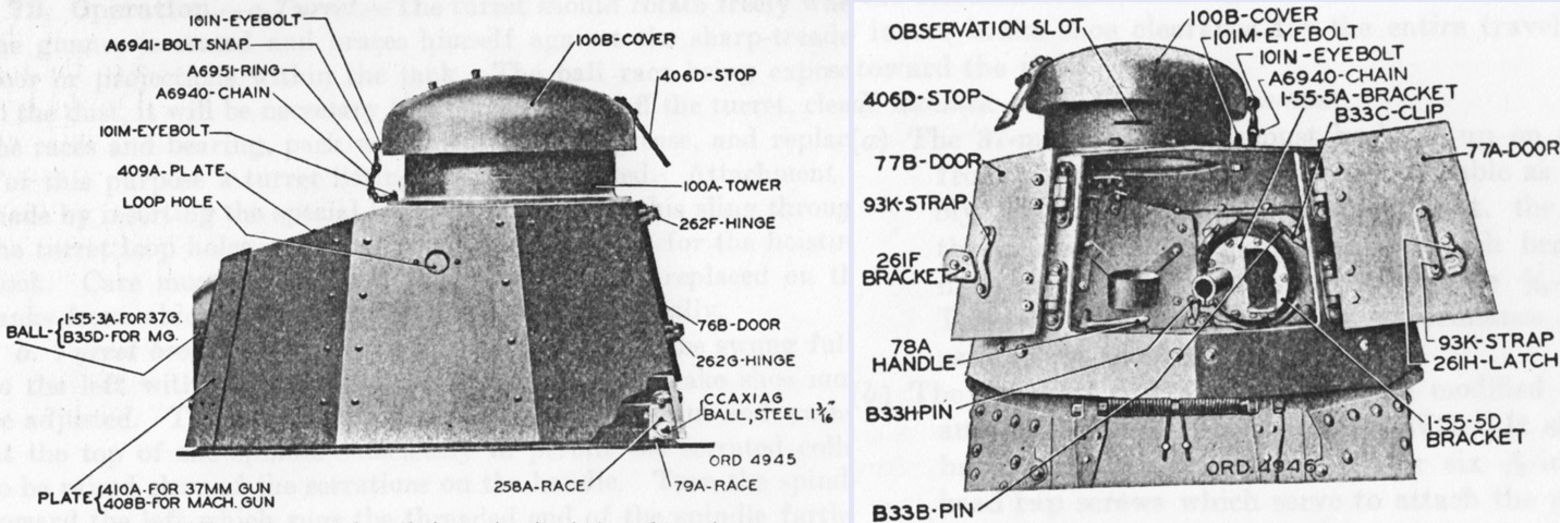
The turret was rotated by the gunner simply bracing himself against the sharp-treaded floor or various projections within the tank. Front plates could be attached that contained different gun mounts, including an 11⅞" (30.163cm) ball mount for the 37mm gun or a 9.1" (23cm) ball mount for the Browning tank machine gun. A turret brake permitted the turret to be locked at any position, and eight turret retaining clamps ensured the turret would not be lost if the vehicle overturned. (Picture from TR 1325-A Tanks: Six-ton Tank, M1917.)
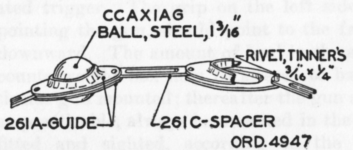
The turret was traversed on eighteen 1.1875" (3.0163cm) steel balls which were confined in V-shaped grooves found in the lower turret race attached to the hull and the upper turret race attached to the turret. (Picture from TR 1325-A Tanks: Six-ton Tank, M1917.)
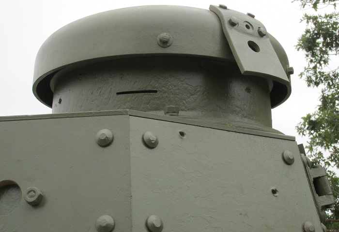
The commander's cupola did not open all the way, and the stop attached to the rear of the cupola is seen here.
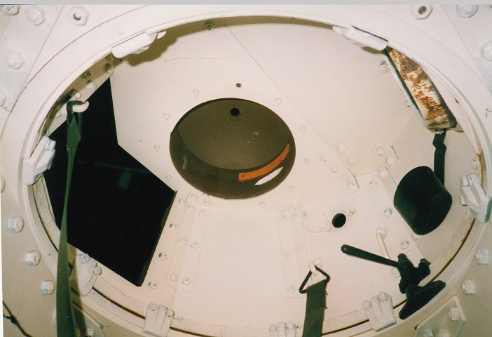
The turret interior of the M1917 is visible here. The open rear door is to the left in this view, with the gun mount to the right. The commander's tower is painted green, and a loophole is visible towards the right of the picture. A canteen holder is mounted by the gun mount, and a sling seat for the commander is hooked on the mounts on either side of the turret.
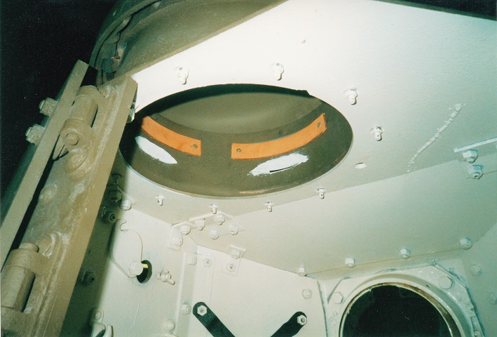
This is a closer view of the commander's tower. The observation slots are overpainted with white on this vehicle, and the leather padding for the commander's head is obvious. The turret rear was composed of two doors, and the left door is just visible here.
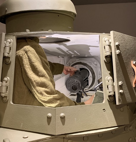
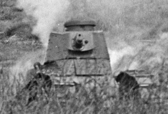
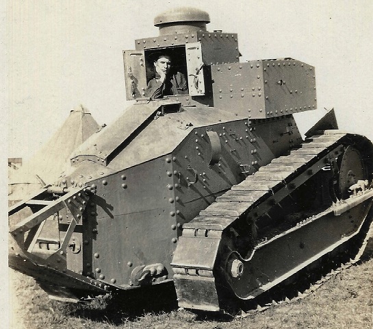
The diminutive size of the tank is well illustrated by the mannequin standing in the turret of this 37mm-armed M1917.
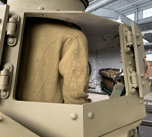
A 25-round 37mm ammunition stowage rack was mounted on the right side of the turret.
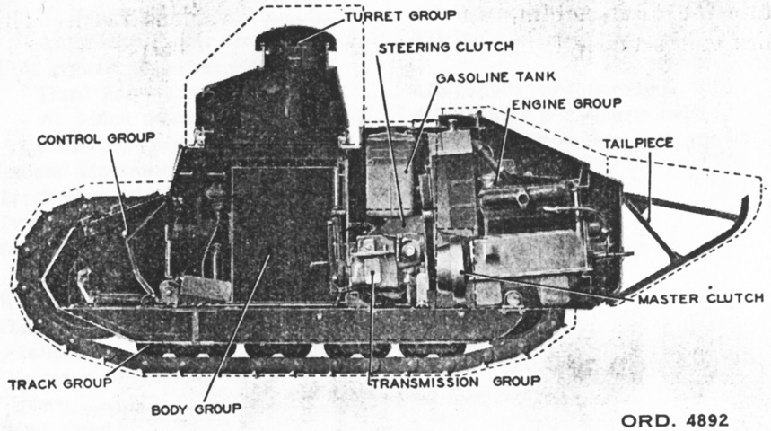
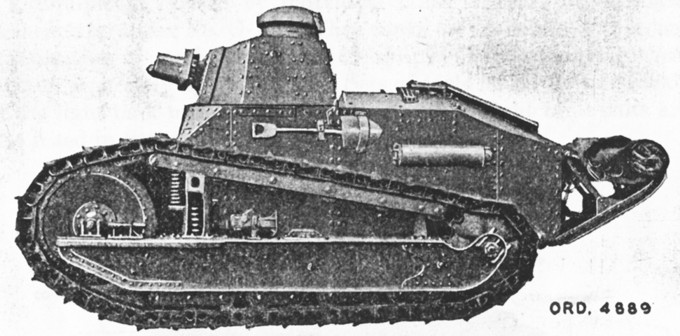
A cross-section of the tank is sketched here showing its various parts groups. The engine was at the rear of the tank, and drove forward into the transmission which was just behind the fire screen. (Picture from TR 1325-A Tanks: Six-ton Tank, M1917.)
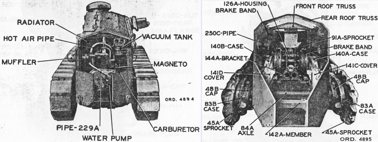
The engine compartment is seen with the armor partly removed on the left, and on the right with the turret, hull armor plates, engine, radiator, and gasoline tank removed. (Picture from TR 1325-A Tanks: Six-ton Tank, M1917.)
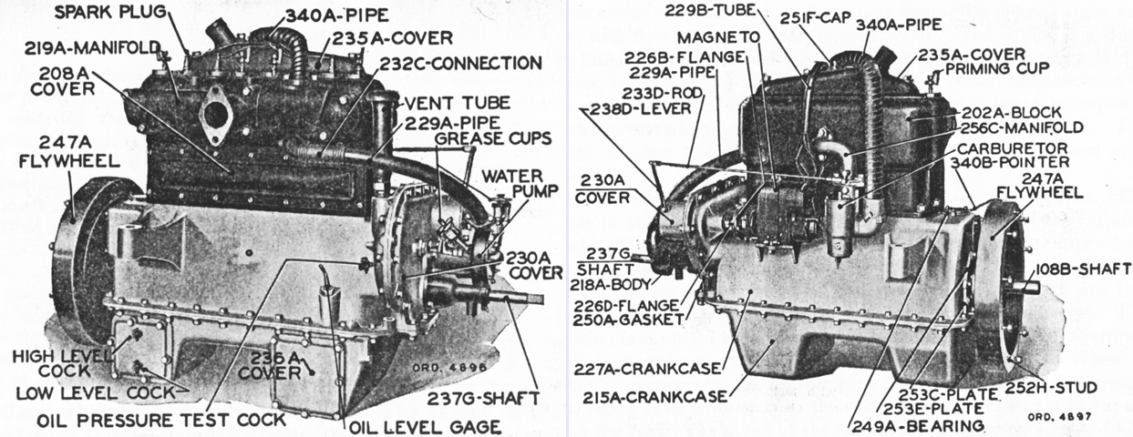
The exhaust and inlet sides of the engine are labeled on the left and right, respectively. Bore was 4¼" (10.8cm) and stroke was 5½" (14cm) for a displacement of 312in³ (5,110cm³). The grease cups initially used to lubricate the water pump impeller shaft were later replaced by pipe plugs. (Picture from TR 1325-A Tanks: Six-ton Tank, M1917.)
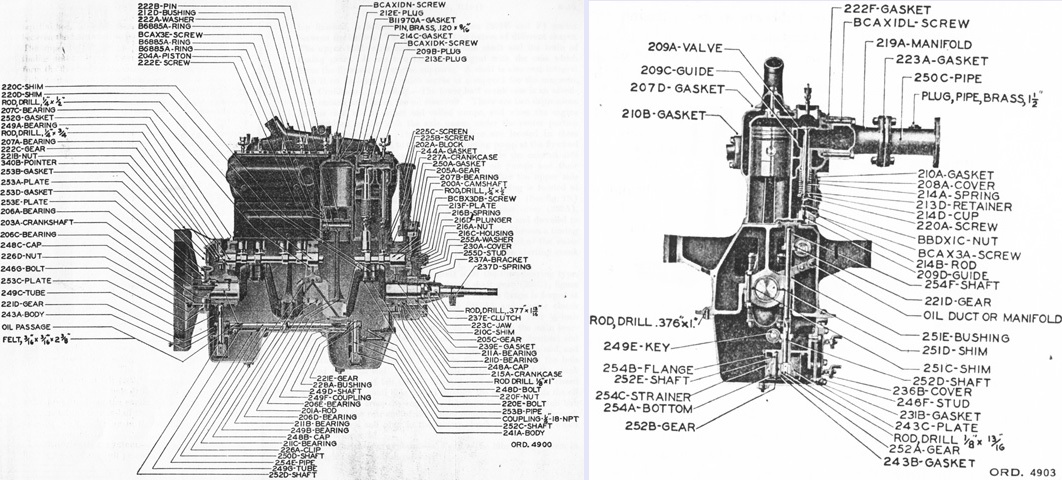
Cross-sections of the engine are sketched here. Firing order was 1-3-4-2, with cylinder number 1 being at the timing gear end. The crankcase held 4gal (15L) of oil, and a Wheeler-Schebler type M-A 1½" (3.8cm) carburetor was used. (Picture from TR 1325-A Tanks: Six-ton Tank, M1917.)
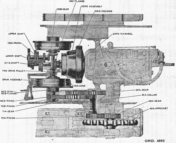
An overhead view of the engine and transmission is shown. Power flowed from the engine forward through the cone clutch and transmission and then back to the drive sprockets through the spur reduction gears on each side of the tank. (Picture from TR 1325-A Tanks: Six-ton Tank, M1917.)
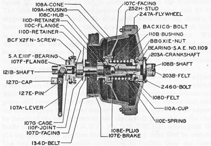
The master clutch is sectioned in this drawing. Its driving member was the clutch housing, which was bolted to the flywheel face. An extension of the housing formed the fan driving pulley. The clutch cone driven member was an aluminum casting with woven asbestos fabric facing riveted to it. (Picture from TR 1325-A Tanks: Six-ton Tank, M1917.)
The front and rear of the transmission are seen at the left and right, respectively. The housing was aluminum, and gear ratios for the four forward speeds were 3.13, 1.54, .94, and .61 to 1. (Picture from TR 1325-A Tanks: Six-ton Tank, M1917.)
The right side of the transmission and steering clutches assembly is labeled. The transmission held 2.5gal (9.5L) of oil. Road speed at 1,466 engine rpm was 1.1mph (1.8kph) in 1st and reverse gears, 2.2mph (3.5kph) in 2nd gear, 3.5mph (5.6kph) in 3rd gear, and 5.5mph (8.9kph) in 4th gear. (Picture from TR 1325-A Tanks: Six-ton Tank, M1917.)
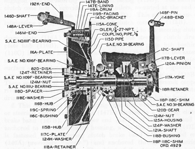
A cross-section of the left side of the transmission is sketched on the left, and a sectionalized drawing of the transverse bevel gear drive is on the right. Power from the engine progressed through the transmission's lower shaft, up through the selected set of gears, back to the transmission bevel pinion (120A in the right drawing) and gear (120B) at the rear of the transmission housing, and then to the cross-shaft (121A), through the steering clutches, and back to the inner spur gear reduction on each side of the tank, further back via an Oldham coupling to the outer reduction gears, and finally to the drive sprockets. (Picture from TR 1325-A Tanks: Six-ton Tank, M1917.)
A cross-sectioned steering clutch and brake assembly is sketched here. The assembly was composed of a steering clutch cone, steering clutch drum, and the brake unit on the outside of the steering clutch drum. One assembly was mounted on each end of the splined cross-shaft that carried power from the transmission to the inside reduction gear. Steering was accomplished by pulling the appropriate steering lever to the rear, which would declutch the desired inner track. Pulling further on the lever would activate the brake, arresting the motion of all drive units for the affected track, thereby tightening the turn. (Picture from TR 1325-A Tanks: Six-ton Tank, M1917.)
This picture is taken from above and behind the drive sprocket, facing forward. The reduction gearing from the transmission to the drive sprocket works its way backwards.
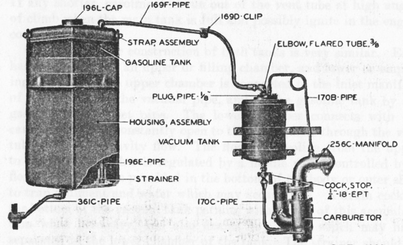
The gasoline tank was made of pressed steel, and was contained in a felt-strip lined pressed-steel housing. If the fuel tank was punctured, the housing could catch the leaking fuel and drain it outside the hull via a copper pipe. Fuel was drawn by suction to a vacuum tank, and then to the carburetor by gravity feed. Initially, the vacuum tank was a Stewart-Warner Model 146A, but after this type was discontinued it was switched to a Stewart-Warner Model 147A. The 146A was D-shaped with a flat back, and had a lower reserve, or gravity, chamber capacity of ~5¼ pints (~2.48L). The 147A was cylindrical in shape with a lower reserve capacity of ~4 pints (~1.89L). (Picture from TR 1325-A Tanks: Six-ton Tank, M1917.)
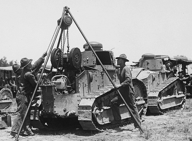
This tank is having its transmission removed. The large brake drum assemblies are the transmission's most prominent feature in this image. The engine in the M1917 was to the rear of the transmission. (Picture taken in 1925 by Harris & Ewing, Inc.; available from the Library of Congress.)
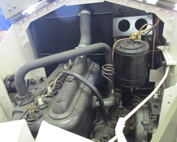
The engine compartment doors are open on this machine, allowing a view of the Buda HU engine. The radiator is visible to the front, and the engine's flywheel would be facing forward to the transmission. The transmission was ahead of the engine, and a gear train worked its way back to the drive sprockets, part of which can be seen in the bolted enclosure to the lower right. The black cylindrical vacuum chamber that transported fuel from the fuel tank to the carburetor is beside the engine at the right.
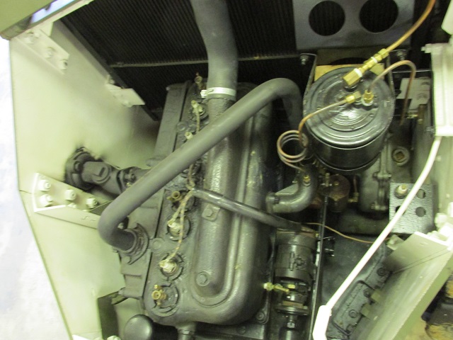
This more vertical view shows the exhaust manifold and outlet to the muffler through the left-hand armor plate.
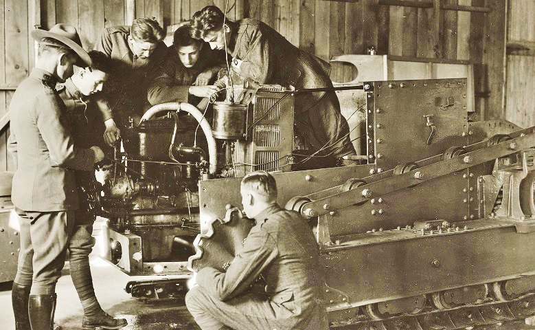
This partially-disassembled tank provides more detail of its engine. (Picture taken 22 Dec 1919 by J.H. Saum; available from the National Archives.)
Typically, starting the engine would be done via the starting crank shaft at the hull rear, but an inside starter was mounted on the front end of the transmission for times when using the exterior starter was not feasible. A button protruded through the fire screen near the floor and, when pressed with a foot, engaged the inside starter clutch so that rotating the handle clockwise would, via a chain and gear, rotate the engine through the transmission and master clutch. (Picture from TR 1325-A Tanks: Six-ton Tank, M1917.)
This Marine tank is one of the signals vehicles that came equipped with a fixed superstructure mounting a radio instead of a gun turret. The radio set used was originally the tank radiotelegraph SCR-78A, which could both send and receive signals out to 6 miles (10km) to headquarters or 3 miles (5km) to another tank. By 1934, this was widely being replaced by the lighter SCR-189, which could send radiotelegraph signals to 8 miles (13km) while in motion and voice signals to 3 miles (5km). This version of the tank weighed 15,400lbs (6,990kg) and was 70.5" (179cm) tall. The crew remained 2 men, both of whom can be seen through their open hatch doors. (Picture from Tank Data, vol. 2.)
The doors on this tank are shut, and a radio antenna can be seen rising from the rear of the superstructure. Note the superstructure's overhang on both sides of the hull, and that the superstructure hatch door spring on the tank's left side is broken. (Picture available from the National Archives.)
The superstructure was provided with a door in the rear as well. The downward slope of the forward superstructure is also more easily seen from this angle. This soldier and tank were part of the 35th Tank Company, Missouri National Guard, and were taking part in its annual training in August 1926. (Picture courtesy Jeremy P. Amick.)
The obvious visual difference between the M1917 and M1917A1 is the latter's longer and taller engine compartment. This was necessary to accommodate the bigger Franklin engine. The position of the muffler on the left side of the tank can also be seen in this view. The air intake and exhaust arrangement was changed from the earlier armored cover to three separate grilles on each side of the rear deck. The new side hull plates were single pieces, and not top and bottom halves as found on the base vehicles. The armament in this tank appears to be the Browning machine gun. (Picture from Development of Armored Vehicles, volume 1: Tanks.)
