105mm Gun Tank M1 Abrams.
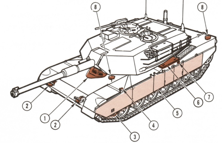
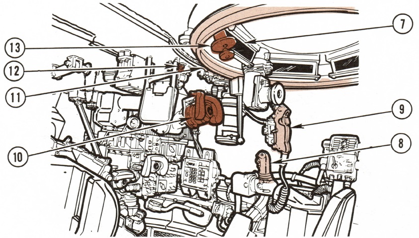
Features visible on the front left of the tank are labeled in this sketch. 1. Driver's hatch. 2. Headlights. 3. Skirt step, left and right side. 4. Hand hold, left side only. 5. Skirts, six on each side. 6. Sponsons, left and right side. 7. External fire extinguisher T-handle. 8. Fuel filler caps. (Picture from TM 9-2350-255-10-1 C3.)
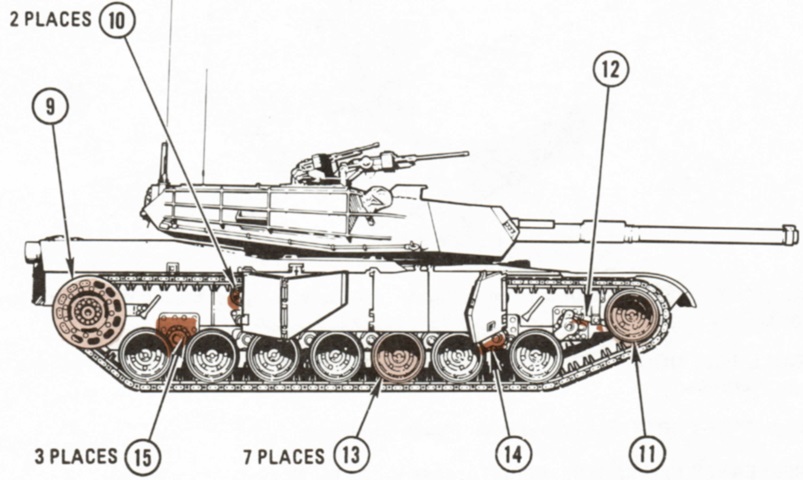
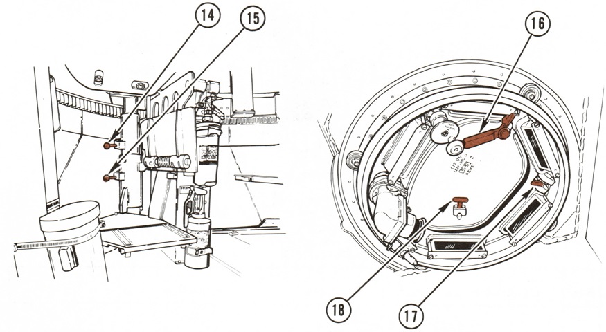
9. Sprocket. 10. Support rollers. 11. Compensating idler wheel. 12. Track adjusting link. 13. Roadwheels. 14. Roadarms. 15. Rotary shock absorber housings. (Picture from TM 9-2350-255-10-1 C3.)
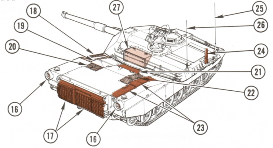
16. Taillights. 17. Rear grille doors. 18. Air intake port. 19. Precleaner doors. 20. Top deck left grille doors. 21. Engine access cover. 22. Top right grille doors. 23. Battery covers. 24. Crosswind sensor. 25. Receiver antenna. 26. Receiver/transmit antenna. 27. Turret stowage boxes, left and right side. (Picture from TM 9-2350-255-10-1 C3.)
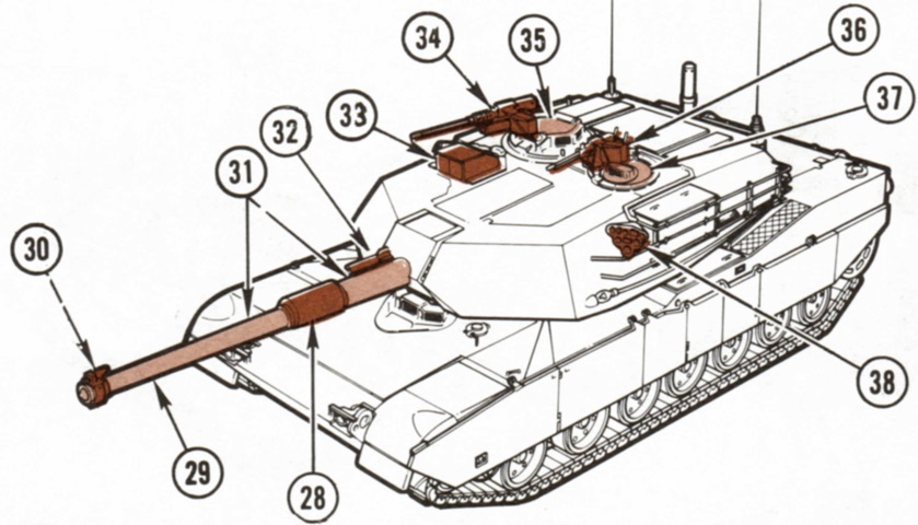
28. Bore evacuator. 29. Main gun - 105mm. 30. Muzzle reference sensor (collimator). 31. Thermal shroud. 32. Flash suppressor. 33. Gunner's primary sight ballistic shield cover. 34. Commander's weapons station (CWS) machinegun. 35. Commander's hatch. 36. Loader's machinegun. 37. Loader's hatch. 38. Smoke grenade discharger. (Picture from TM 9-2350-255-10-1 C3.)
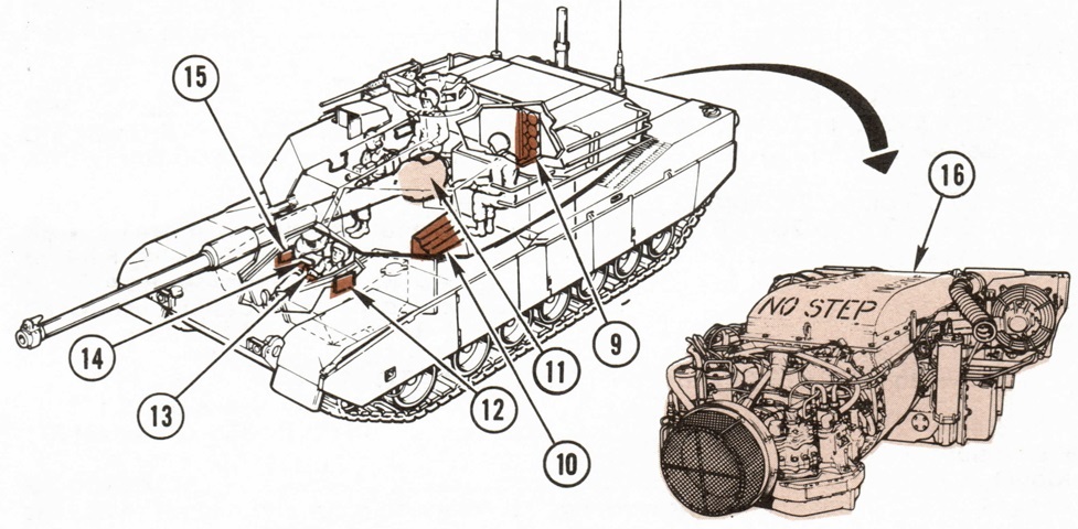
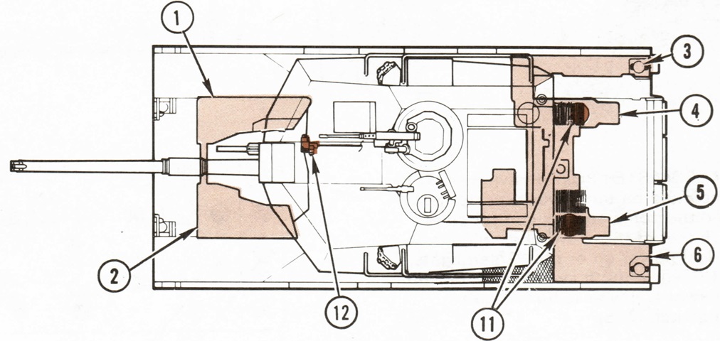
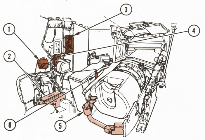
The crew and some interior features are shown in this cross-section. 9. 105mm bustle ammunition compartment. 10. 105mm turret floor ready rack. 11. Main gun breech. 12. Driver's instrument panel. 13. Steer-throttle control. 14. Driver's alert panel. 15. Driver's master panel. 16. Powerpack. (Picture from TM 9-2350-255-10-1 C3.)
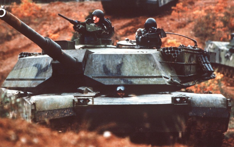
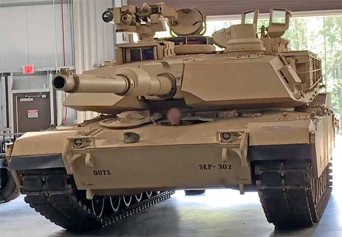
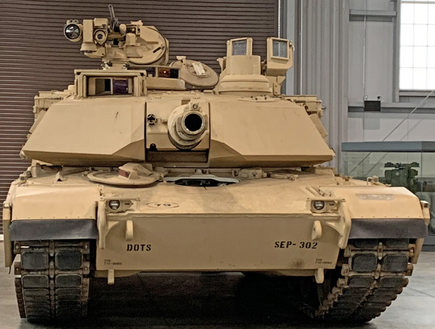
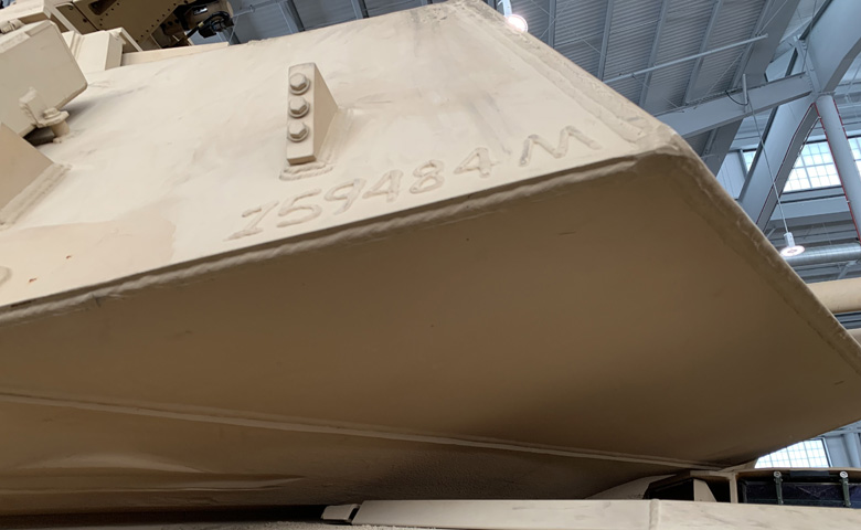
The slab-faced turret dictated by the special armor within is perhaps the M1's most striking contrast from the cast turret tanks fielded before it. (Picture taken 1 Jan 1983; available from the Defense Visual Information Center.)
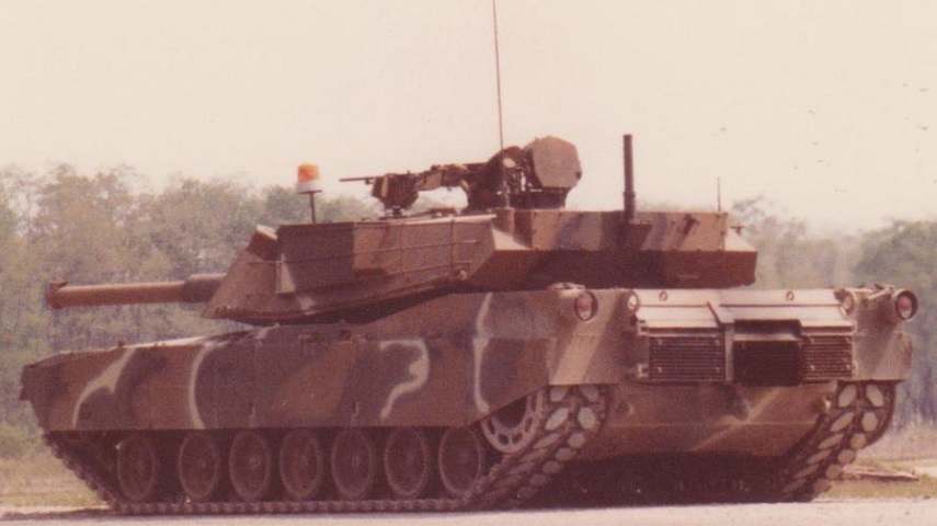
This early tank features the track retaining ring on the rear drive sprocket and the original rear track skirt. This design allowed dirt to build up underneath and resulted in thrown tracks, so it was redesigned to incorporate a notch around the drive sprocket. The rear of the turret was ringed with tie downs for external stowage; this was also replaced later with a stowage rack in the rear. (Photo by Richard S. Eshleman.)
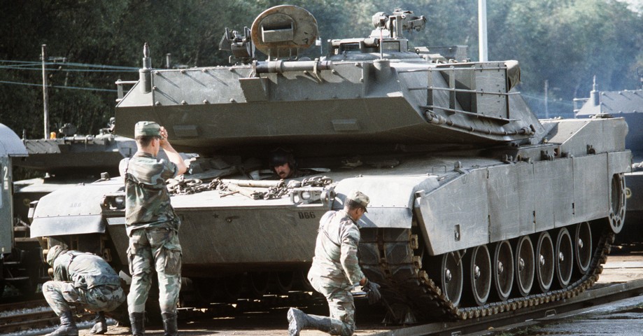
This tank has the track retaining ring on the rear drive sprocket, but has the newer notched rear skirt design that helped prevent dirt buildup. T156 tracks with integral rubber pads are on this tank. There are antenna mounts on the rear corners of the turret, and the crosswind sensor is folded over in the middle of the turret bustle's rear. (Picture taken 15 Aug 1984 by SPC5 Vincent Kitts; available from the Defense Visual Information Center.)
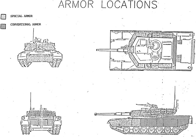
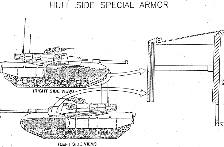
This image details where the special armor arrays were arranged: the forward armor skirts, turret front and sides, and the lower hull front. (Picture from "Special Armor Security Classification Guide.")
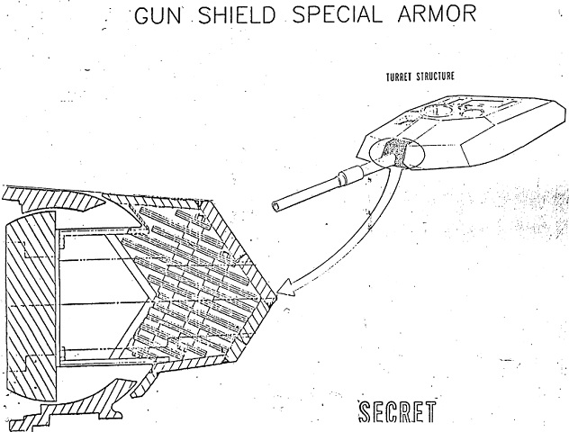
The structure of the gun shield is diagrammed here. The internal diagonal plates would offer some movement when struck, helping to destabilize and break up incoming projectiles. (Picture from "Special Armor Security Classification Guide;" sanitized for release on 2014/03/04.)
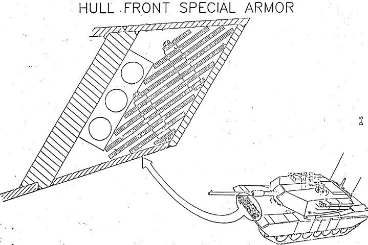
The hull front armor array differs in detail from the gun shield, but functions in a similar manner. (Picture from "Special Armor Security Classification Guide.")
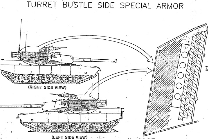
The turret sides were also protected by a composite armor array. (Picture from "Special Armor Security Classification Guide.")
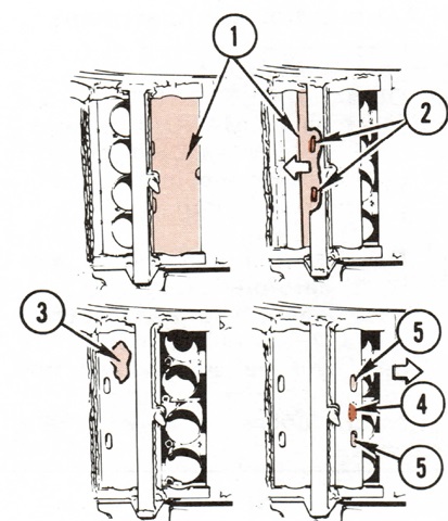
The forward ballistic skirts are cross-sectioned in this sketch. The right side of the tank featured additional protection to guard the hull ammunition bin located in the right rear of the fighting compartment. (Picture from "Special Armor Security Classification Guide.")
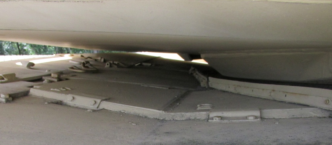
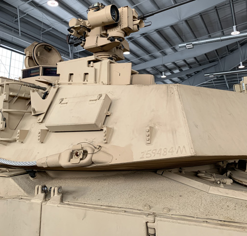
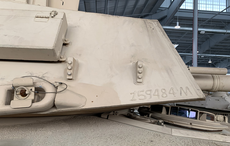
The difference in thickness between the special armor skirt panel on the left and the regular skirt panel on the right is obvious.
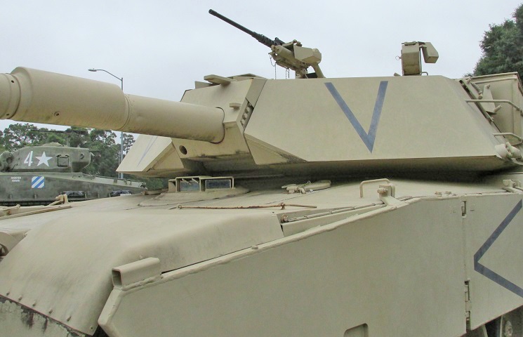
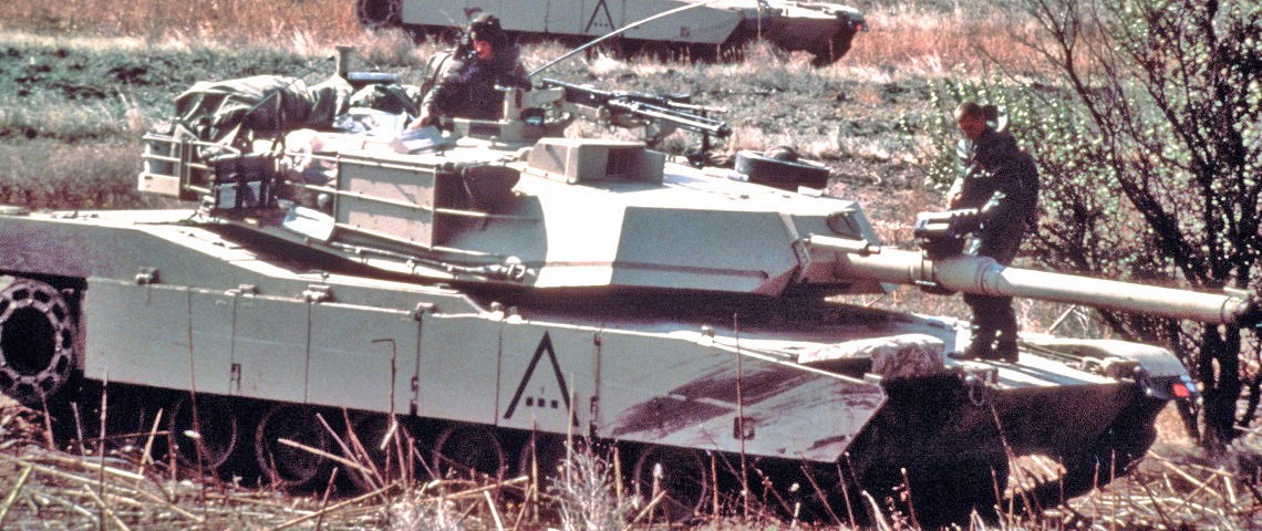
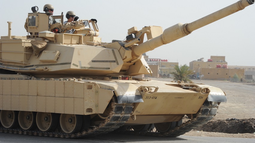
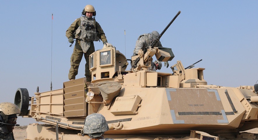
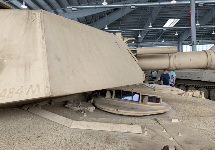
A machine gun rests in the commander's mount, although the loader's weapon is absent. Likewise, the bracket for the M250 smoke grenade launcher can be seen in front of the stowage box on the turret side, but the launcher itself is not mounted. The shape of the front turret and size of the main gun on this tank can easily be contrasted with the 120mm gun tanks below.
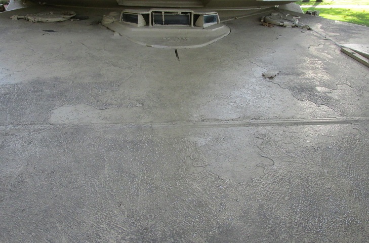
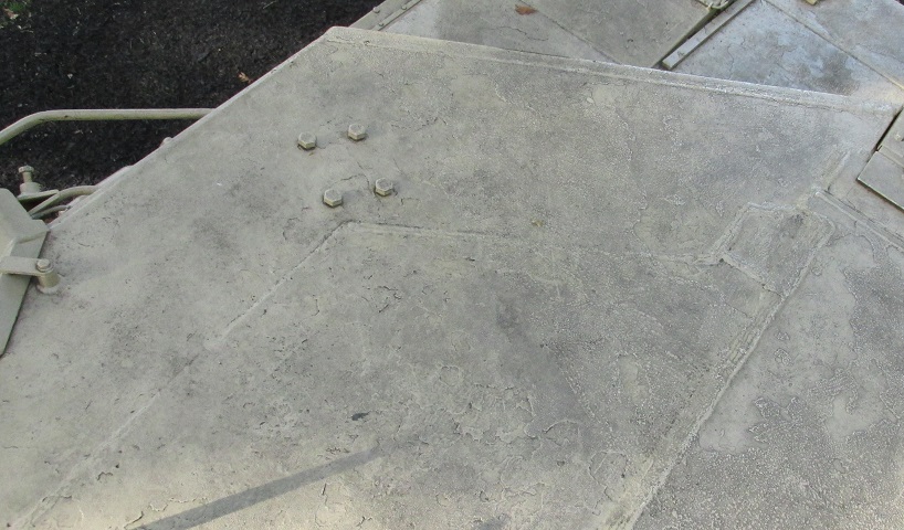
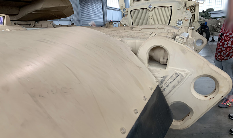
The hatch is in place in this picture, flanked by two fuel fillers. The driver's left-side wiper is missing, but its base can be seen atop the central periscope. This center periscope was the one replaced with the image intensifying periscope when the driver prepared for night operations. The crosswise weld line in the foreground is related to the construction of the special armor in the front hull.
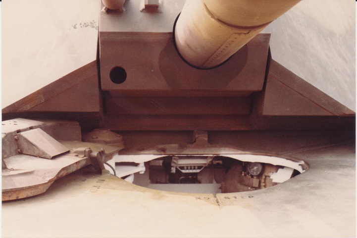
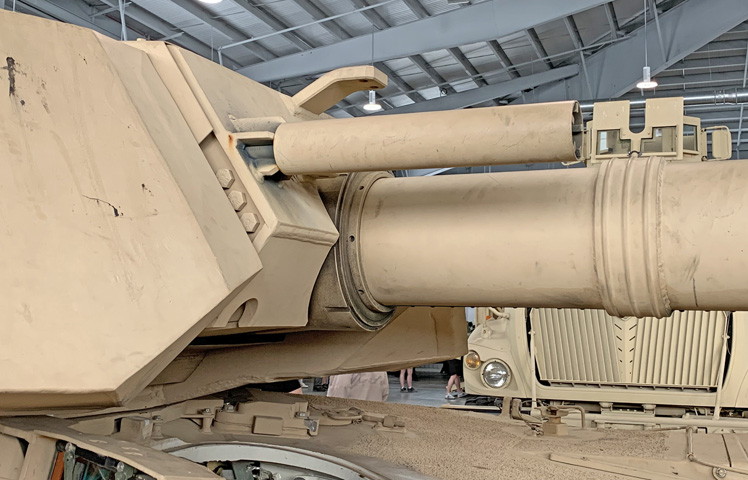
The extreme slope of the tank's glacis forced the driver to sit in a reclined position. Details of the 105mm gun mount are also visible, including the aperture for the gunner's auxiliary sight on the bottom and the base of the barrel shroud for the 7.62mm coaxial MG directly above this. The opening for the gunner's auxiliary sight can be contrasted with tanks below whose armor has been strengthened (beginning with the IPM1), where it became a channel on the underside of the gun mantlet. (Photo by Richard S. Eshleman.)
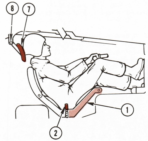
The driver's supine orientation is illustrated here. 1. Seat. 2. Seat locking lever. 7. Headrest. 8. Headrest adjusting knob. (Picture from TM 9-2350-255-10-2 C3.)
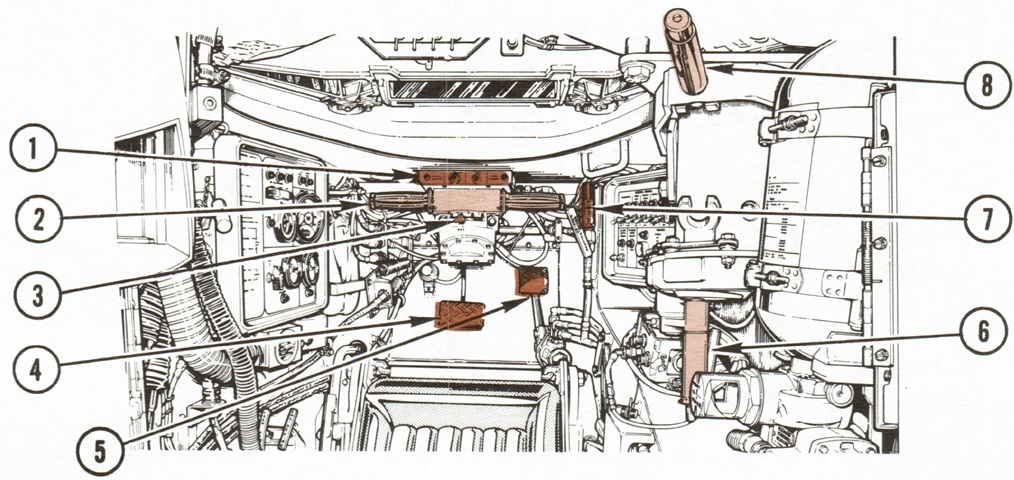
The interior of the driver's station is drawn in this image. 1. Alert panel. 2. Steer-throttle control. 3. Transmission shift control. 4. Service brake pedal. 5. Parking brake pedal. 6. Hatch opening crank. 7. Parking brake system hydraulic pressure gage. 8. Hatch lifting handle. (Picture from TM 9-2350-255-10-1 C3.)
9. Driver's master panel. 10. Periscope adjustment knobs. 11. Fire detector sensor. 12. Driver's instrument panel. 13. Remote intercom switches. 14. Fire extinguisher bottle pressure gage. (Picture from TM 9-2350-255-10-1 C3.)
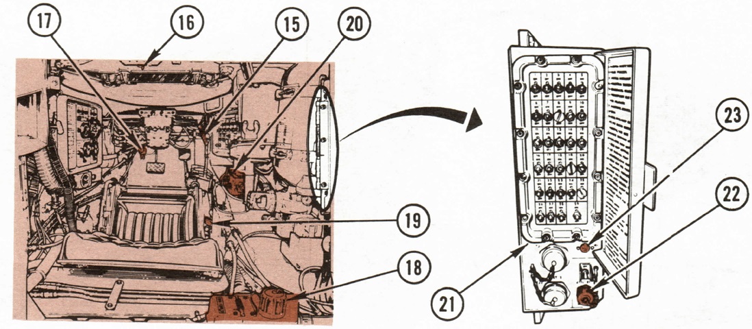
15. Parking brake release handle. 16. Driver's periscope wiper lever. 17. Periscope washer pump. 18. Hull power distribution box. 19. Drain valve handles. 20. Intercommunication control (C-10456/VRC). 21. Hull networks box. 22. UTIL OUT electrical outlet for light extension cord. 23. Engine hour meter. (Picture from TM 9-2350-255-10-1 C3.)
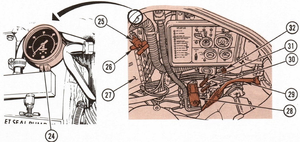
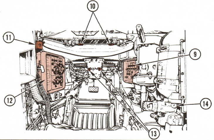
Features of the left side of the driver's compartment are shown here. 24. Turret seal pressure gage. 25. Inflatable turret seal pump. 26. Personnel heater duct control lever. 27. Night vision viewer stowage. 28. M3 heater. 29. Open/closed hatch seat control lever. 30. ENGINE FIRE T-handle. 31. CREW FIRE T-handle. 32. Air direction control knob. (Picture from TM 9-2350-255-10-1 C3.)
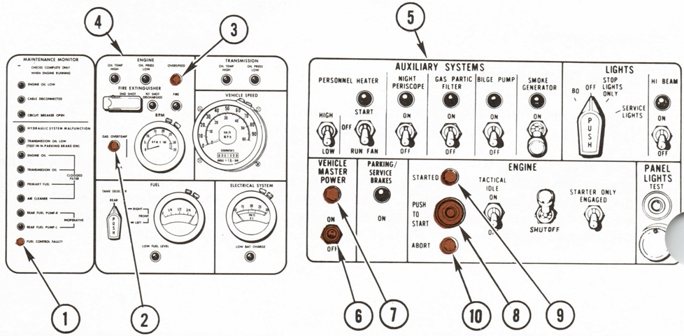
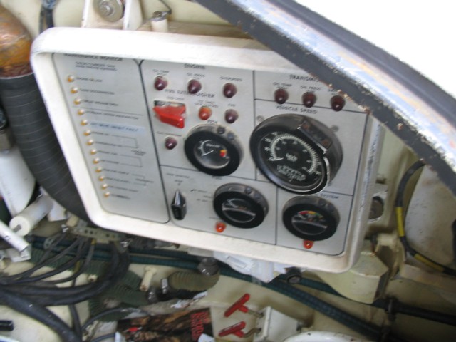
The driver's panels are reproduced in this image. 1. FUEL CONTROL FAULTY light. 2. GAS OVERTEMP light. 3. ENGINE OVERSPEED light. 4. Driver's instrument panel. 5. Driver's master panel. 6. VEHICLE MASTER POWER switch. 7. VEHICLE MASTER POWER light. 8. START switch. 9. STARTED light illuminated for 10 seconds when the electronic control system sensed the engine had reached idle speed. 10. ABORT light illuminated for 10 seconds if the electronic control system aborted an engine start.
From top to bottom, the indicator lights above the FUEL CONTROL FAULTY light were ENGINE OIL LOW; major hull electrical CABLE DISCONNECTED; CIRCUIT BREAKER OPEN; HYDRAULIC SYSTEM MALFUNCTION; TRANSMISSION OIL LOW; clogged filters for the ENGINE OIL, TRANSMISSION OIL, PRIMARY FUEL, and AIR CLEANER; REAR FUEL PUMP R[ight] INOPERATIVE; and REAR FUEL PUMP L[eft] INOPERATIVE. To the left of the ENGINE OVERSPEED light was the ENGINE OIL PRESS LOW light, and to the left of this was the OIL TEMP HIGH light. To the right of the ENGINE OVERSPEED light was the TRANSMISSION OIL TEMP HIGH light, and to the right of this was the TRANSMISSION OIL PRESS LOW light. The largest dial was the speedometer, and the smaller dial to the left was the tachometer. Centered directly above the tachometer was the light indicating that the engine fire extinguisher's 1ST SHOT DISCHARGED; to the right of this was the engine FIRE light. To the left was the switch for the second shot of the engine fire extinguisher. This shut down the engine and discharged the fire extinguisher after 18 seconds. The dial below the tachometer was the fuel gage. The TANK SELECTOR switch picked which tank to indicate on the gage, and this also turned on the front fuel pump when the LOW FUEL LEVEL light, under the fuel gage, was lit. To the right of the fuel gage was the voltmeter, and below this was the LOW BAT CHARGE light.
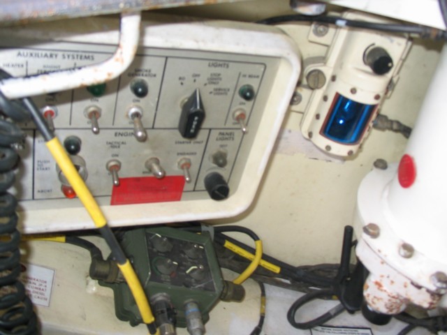
On the master panel, from left to right on the top row were switches to activate the personnel heater high or low temperature settings and fan; switch and indicator light to supply power to the driver's night periscope; switch and indicator light to supply power to the gas particulate filter; switch and indicator light to supply power to the bilge pump; switch and indicator light to supply power to the engine smoke generator; and the external lights and high beam switches. To the right of the VEHICLE MASTER POWER light, the PARKING/SERVICE BRAKES light illuminated when the parking brake was not released or when the service brakes were engaged for more than 2 minutes while the engine was on. To the right of the START switch was the TACTICAL IDLE switch to set the engine idle at ~1350rpm. To the right of this, the SHUTOFF switch cut fuel supply to the engine, and to the right again was the STARTER ONLY ENGAGED switch that provided power to turn the engine starter without igniting the engine. A test button for the panel lights and a brightness control knob was in the bottom right. (Picture from TM 9-2350-255-10-1 C3.)
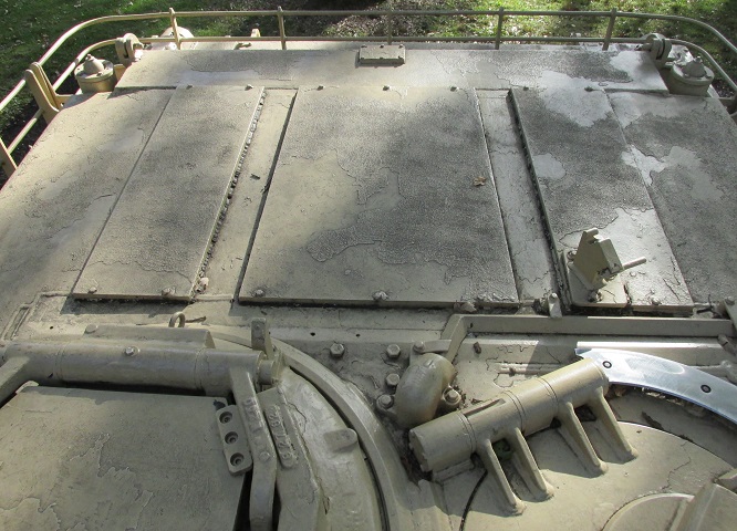
Another view of the tank's glacis and weld line is shown from above. Construction of the gun mantlet and coaxial machine gun flash hider can also be seen. The flap on the rear of the gun mantlet is a cover for the joint between the gun mantlet and turret that is held down by sprung hinges. The mounting lug on top of the gun shield extends straight forward, which would be changed in later models of the tank.
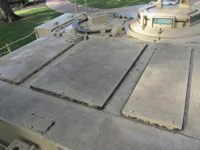
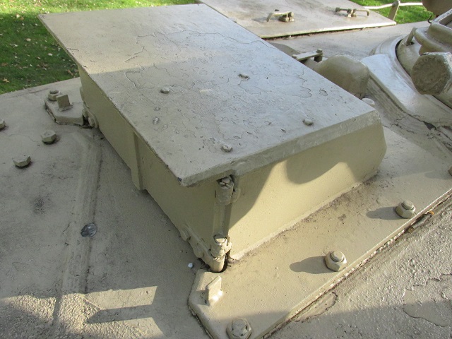
The blowoff panels atop the ammunition stowage in the turret bustle allowed the conflagration caused by detonating ammunition to vent into the air away from the crew. This tank has been retrofitted with a turret bustle stowage rack.
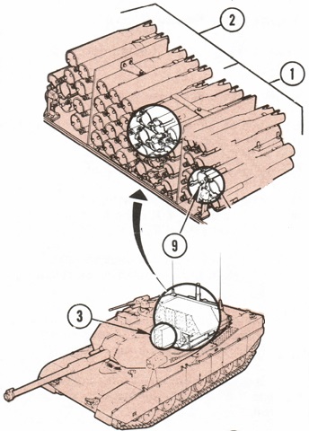
The turret bustle and hull ammunition stowage racks are drawn here. The bustle ready stowage incorporated fourteen standard racks, four swing tubes, and a four-round rotary rack. The semi-ready stowage accommodated a further twenty-two rounds. A rotating disc on the tube allowed the loader to keep track of which ammunition type was which; the disc was rotated so that a letter indicating the ammunition type was at the top (S for sabot; B for beehive; P for high-explosive, plastic; and H for high-explosive antitank). 1. Ready ammunition compartment. 2. Semi-ready ammunition compartment. 3. Hull ammunition compartment. 9. Rotary rack. (Picture from TM 9-2350-255-10-2 C3.)
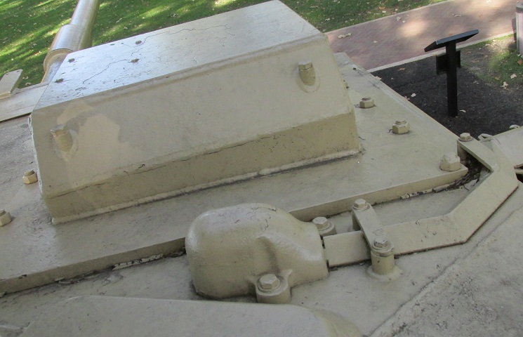
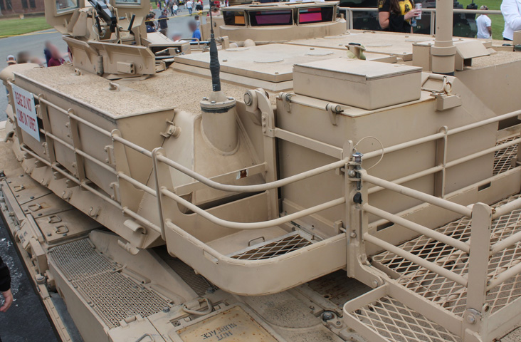
Once the stowage basket was introduced, it was commonly retrofitted to earlier tanks. The mount for the crosswind sensor can be seen in the lower left, while a fuel filler is at the corner of the hull in the opposite corner.
The fuel system is shown here. There were two front fuel tanks and one rear tank that was divided into four interconnected fuel cells. The engine was fed from the rear tank only; when the LOW FUEL LEVEL light was illuminated and the driver selected a forward tank with his TANK SELECTOR switch, fuel was transferred from the selected tank to the rear tank. 1. Right front fuel tank. 2. Left front fuel tank. 3. Right sponson fuel cell. 4. Right engine fuel cell. 5. Left engine fuel cell. 6. Left sponson fuel cell. 11. Rear tank fuel pumps. 12. Forward tanks fuel pump. (Picture from TM 9-2350-255-10-1 C3.)
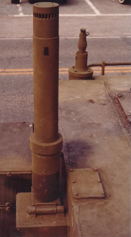
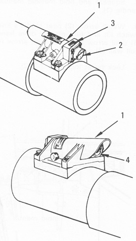
Details of the mounted T.S.I. crosswind sensor can be seen in this image. Note the hinge at the base to allow it to be folded over when not in use, as in the image above. (Photo by Richard S. Eshleman.)
Looking forward from the stowage basket, the loader's hatch on the left and the commander's cupola on the right are just in front of the ammunition blowoff panels. Emerging from the roof between the two hatches is the wiring for the left-side smoke grenade launcher, which then snakes its way around the loader's hatch to the turret side.
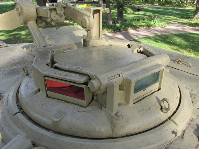
The rear of the commander's cupola and the cradle for the .50cal machine gun are seen here. The sight for the machine gun would be found in the vertical guard to the right of the machine gun.
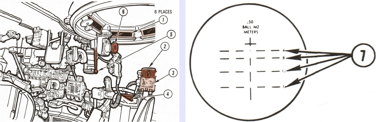
The tank commander's position is highlighted on the left, and the reticle for his weapon sight is on the right. The sight provided 3x magnification, and the commander also had the option of using steel sights by looking through the front unity periscope. 1. Unity periscopes. 2. Frequency selector control (C-2742/VRC). 3. Intercommunication control (C-10456/VRC). 4. Commander's panel. 5. POWER/MANUAL lever. 6. Commander's weapon sight. 7. Range in hundreds of meters. (Picture from TM 9-2350-255-10-1 C3.)
The tank commander's position is continued. 7. Forward unity periscope. 8. Commander's power control handle. 9. Commander's weapon station power control handle. 10. Commander's gunner's primary sight (GPS) extension eyepiece. 11. Commander's weapon station manual traverse ring. 12. Commander's remote intercom switch. 13. Commander's elevation crank. (Picture from TM 9-2350-255-10-1 C3.)
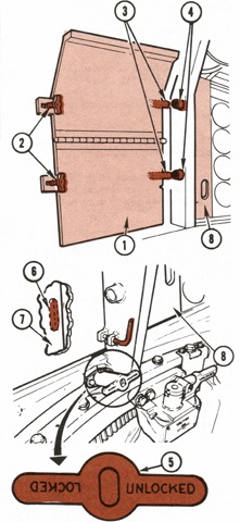
The tank commander's position is continued. 14. Seat height adjustment knob. 15. Platforms height adjustment knob. 16. Operating handle to latch and unlatch hatch in closed position. 17. Locking lever to unlock hatch from protected open and full open positions. 18. T-handle to lock and unlock hatch in yoke assembly. (Picture from TM 9-2350-255-10-1 C3.)
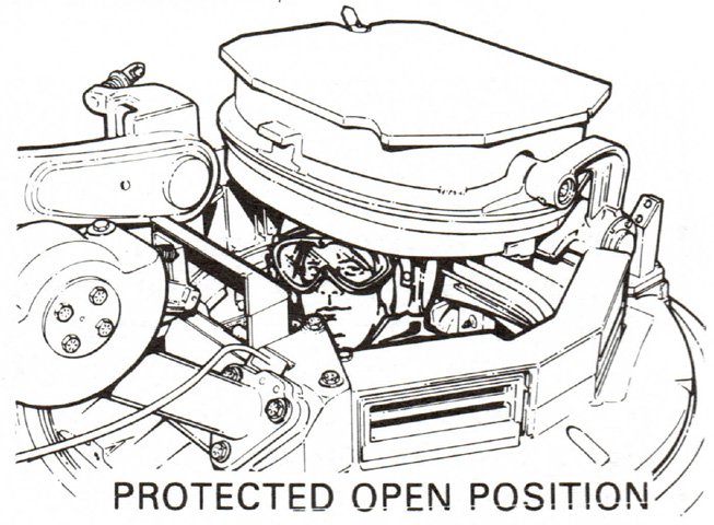
The cupola hatch could be fully closed, fully open, or locked in the protected open position as shown above, which provided the commander an unobstructed view while retaining overhead protection. (Picture from TM 9-2350-255-10-1 C3.)
The loader's hatch is seen in this image from behind the commander's cupola. The skate rail for his machine gun and the periscope guard in his hatch are obvious.
The front of the loader's hatch is shown, revealing more details of the machine gun cradle and his periscope.
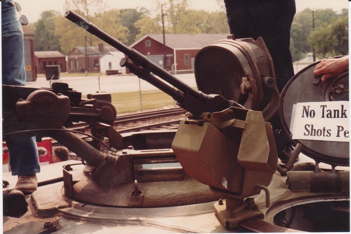
The crew hatches are open on this tank, and the roof machine guns are mounted. The loader's weapon is mounted on a skate rail and the empty ammo box cradle is on the gun's left, while the commander's MG was fired from under armor. It was elevated manually, but could be traversed electrically. (Photo by Richard S. Eshleman.)
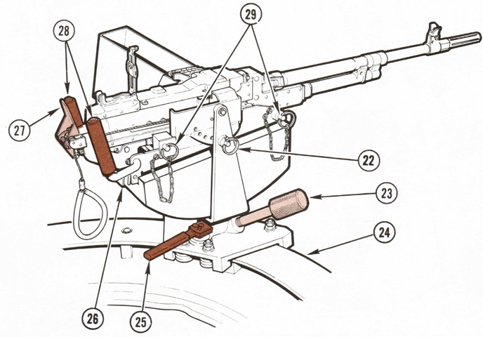
The loader's machine gun and mount are detailed in this sketch. 22. Elevation lockpin. 23. Azimuth lock. 24. Skate rail. 25. Skate lock. 26. Spent case lockpins. 27. Trigger. 28. Spade grips. 29. Mounting pins. (Picture from TM 9-2350-255-10-1 C3.)
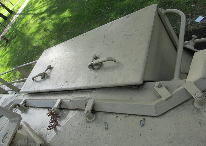
The loader's stowage box is shown here; a similar box was found beside the commander. The previously-mentioned wiring for the smoke grenade launcher can be found under the shroud on the roof.
The loader's controls are seen from across the breech of the 105mm gun. 1. Intercommunication control (C-10456/VRC). 2. Turret networks box. 3. Receiver (R-442/VRC). 4. Receiver-transmitter (RT-246/VRC). 5. Main gun spent case ejection guard. 6. Main gun breech operating handle. (Picture from TM 9-2350-255-10-1 C3.)
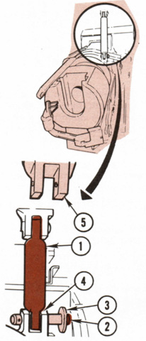
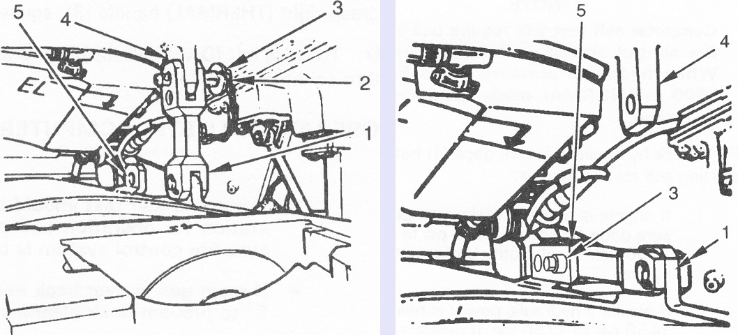
The main gun was provided with an elevation travel lock in the turret interior. The lock pin had a push button that allowed it to be released, and when not in use the travel lock was swung upwards into a bracket on the roof, where the lock pin was reinserted to stow it securely. 1. Elevation travel lock. 2. Button. 3. Lock pin. 4. Main gun bracket. 5. Roof bracket. (Picture from TM 9-2350-255-10-2 C3.)
The left and rear of the loader's position are highlighted here. 7. MAIN GUN STATUS lights. 8. Fire detector sensor. 9. TURRET BLOWER switch. 10. GUN/TURRET DRIVE switch to set gun and turret drive system to powered, manual, or elevation uncoupled mode. 12. Ready ammunition door lock. 13. Semi-ready ammunition door lock. 14. Loader's knee switch (stowed in up position) to open and close ready ammunition bustle door. 15. Turret traverse lock lever. (Picture from TM 9-2350-255-10-1 C3.)
The three-round turret floor ready rack is drawn in this picture. 1. Quick-release pin. 2. Cover. 3. Swing tube. 4. Ammunition type disc. (Picture from TM 9-2350-255-10-2 C3.)
In order to transfer main gun ammunition from the semi-ready rack behind the commander to the ready rack, the ready ammunition door was prepared for manual operation by swinging the kneeswitch up and disconnecting the door from the actuator shaft. Then the commander's ammunition door guard was removed by loosening the thumb screws and releasing the door pins from the holes in the turret. The door was unlocked via the locking handle, and then the door was slid to the right using a cutout in the door and the door's left edge. With both doors free, they were both slid left or right as needed when transferring rounds. 1. Door guard. 2. Thumb screws. 3. Release pins. 4. Holes. 5. Lock handle. 6. Cutout. 7. Front of semi-ready ammunition door. 8. Ammunition door. (Picture from TM 9-2350-255-10-2 C3.)
The gunner's primary daylight and thermal sights (GPS) as well as the laser rangefinder were protected by an armored "doghouse," with shutters that could be opened and closed via a lever at his position. The laser could range on targets from 200m to 7,990m away with an accuracy of ±10m. If the range was between 200m and 4,000m it would automatically be entered into the ballistic computer, but if the target was 4,010m to 7,990m away the range would flash in the GPS but would not automatically be entered into the computer. The laser could be fired once every twenty seconds for continuous use without overheating, and rapid firing could be performed for no more than four pulses with two seconds between each pulse. No more than four pulses were to be fired in an eighty second period.
Behind the GPS housing, the wiring for the right-hand smoke grenade launcher assembly exits the turret roof.
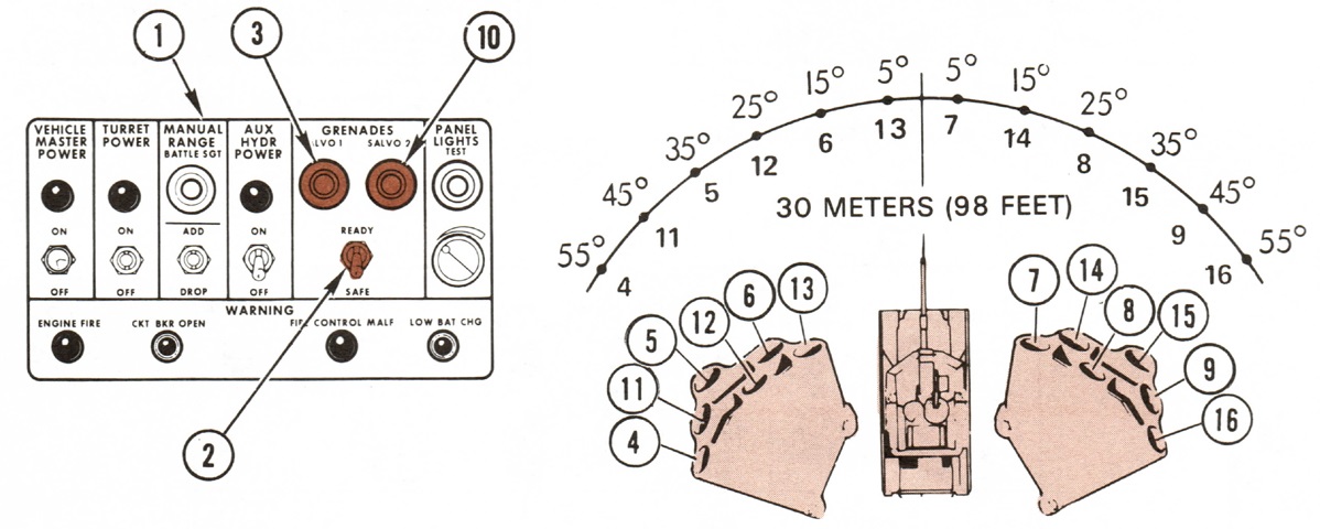
The spread of and controls for the smoke grenade launchers are diagrammed here. 1. Commander's control panel. 2. GRENADES READY/SAFE switch. 3. SALVO 1 button. 10. SALVO 2 button. SALVO 1 involved grenades 4, 5, 6, 7, 8, and 9. SALVO 2 launched the remainder. Both buttons could be pushed at once, launching all the smoke grenades. (Picture from TM 9-2350-255-10-1 C3.)
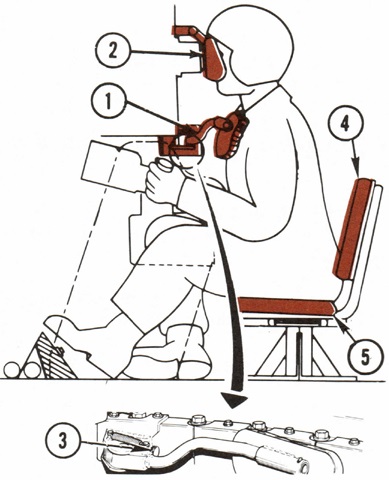
The gunner is drawn here ready to fire, with the chestrest in position and his lower back wedged between his seat back and seat cushion. 1. Chestrest. 2. GPS browpad. 3. Adjustment knob. 4. Seat back. 5. Seat cushion. (Picture from TM 9-2350-255-10-2 C3.)
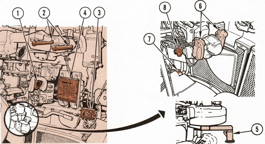
The gunner's controls are highlighted in this drawing. 1. Gunner's primary sight (GPS). 2. GPS ballistic door actuator handles; the daylight and laser rangefinder were protected by the left door, while the thermal imaging system was behind the right. The left door needed to be opened before and closed after the right. 3. Intercommunication control (C-10456/VRC). 4. Computer control panel. 5. Manual traverse crank handle. 6. Gunner's power control handles. 7. Gunner's foot intercom switch. 8. Manual elevation crank handle. (Picture from TM 9-2350-255-10-1 C3.)
The gunner's station is continued. 9. Emergency MANUAL FIRING device (blasting machine). 10. Gunner's auxiliary sight (GAS). 11. GAS control panel. 12. GAS reticle boresight adjustment knobs. 13. Hydraulic pressure gage. 14. Unity periscope. 15. DEFROSTER switch and light for GPS daylight channel. 16. RETICLE knob for GPS reticle brightness. (Picture from TM 9-2350-255-10-1 C3.)
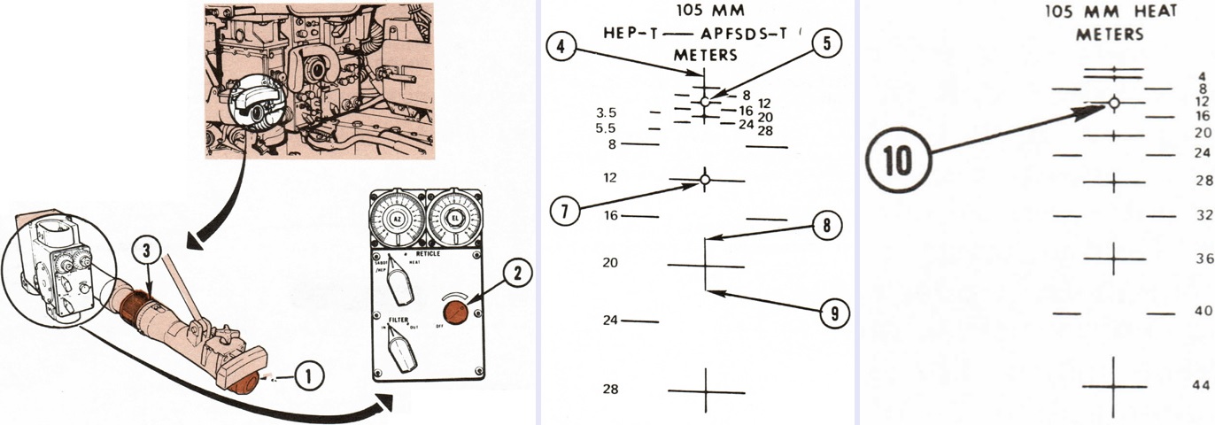
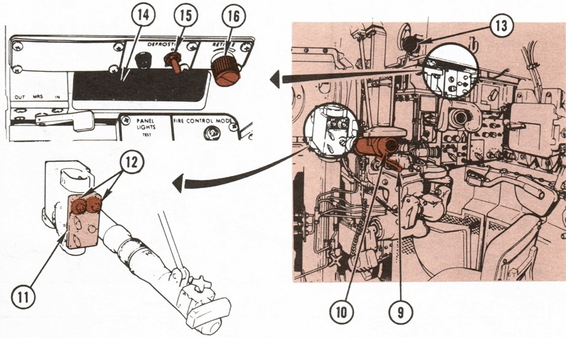
The gunner's auxiliary sight was an 8x articulated telescope, and is isolated on the left. It could be changed between two reticles, one for APFSDS-T and HEP-T as seen in the center, and the other for HEAT as shown on the right. 1. GAS eyepiece. 2. Reticle brightness knob. 3. Focusing ring.
In the center image, center vertical line (4) is broken into segments with the ends showing range points between the marked values. Arrow (8), for example, is showing the 1,800m point and arrow (9) 2,200m. Circle (5) is the zero sighting point for APFSDS-T at the 1,200m mark, and circle (7) is the zero sighting point for HEP-T, also at 1,200m. Each horizontal segment represents the lead required to hit a target moving at 10mph (16kph) at 1,000m away. The HEP reticle could also be used to fire the coaxial machine gun. Circle (10) on the HEAT reticle is the zero sight point at 1,200m. When using APERS ammunition, the gunner would consult a conversion chart attached to the gun mount, and then apply that conversion to the ranges on the HEAT reticle. (Picture from TM 9-2350-255-10-1 C3.)
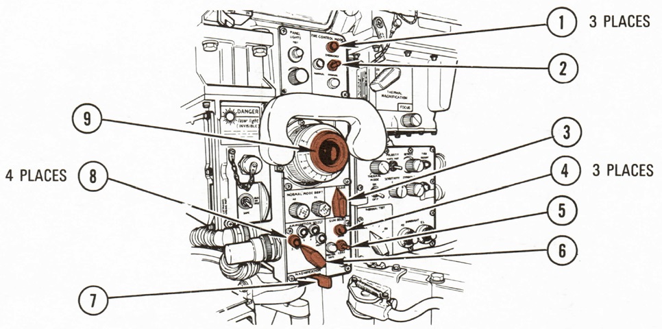
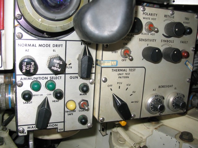
The GPS is highlighted in this drawing. 1. FIRE CONTROL MODE lights indicating normal, emergency, or manual modes. 2. FIRE CONTROL MODE switch. 3. FLTR/CLEAR/SHTR switch to position filter, clear window, or shutter in the GPS day optic system. 4. GUN SELECT lights. 5. GUN SELECT switch to select main or coaxial machine guns, or trigger safe. 6. AMMUNITION SELECT switch. 7. MAGNIFICATION lever to select 3x or 10x. 8. AMMUNITION SELECT lights. 9. Gunner's GPS eyepiece. (Picture from TM 9-2350-255-10-1 C3.)
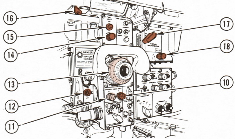
The GPS is continued. 10. NORMAL MODE DRIFT, EL knob corrected for elevation drift in stabilized (normal) sighting system. 11. NORMAL MODE DRIFT, AZ knob corrected for azimuth drift in stabilized (normal) sighting system. 12. RANGE switch selected first return, last return, or safe mode of laser rangefinder. 13. Diopter adjustment. 14. PANEL LIGHTS knob. 15. PANEL LIGHTS, TEST pushbutton. 16. MRS OUT/IN lever controlled the mirror that allowed the muzzle reference system reticle to appear in the GPS optical system. 17. THERMAL MAGNIFICATION lever selected 3x or 10x magnification for the thermal imaging system. 18. FOCUS knob. (Picture from TM 9-2350-255-10-1 C3.)
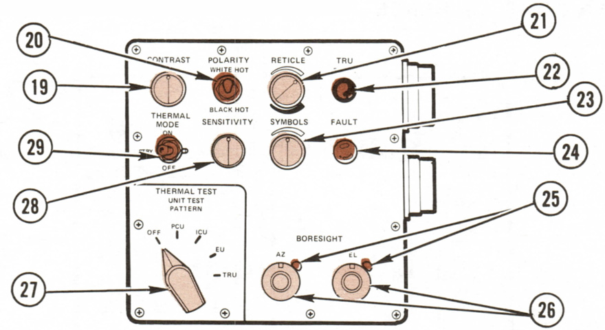
The panel on the lower right of the above image is detailed in this sketch. 19. CONTRAST knob adjusted contrast of the thermal image. 20. POLARITY switch selected white or black hot for the thermal image. 21. RETICLE knob adjusted the whiteness/blackness of the thermal reticle. 22. TRU READY light lit green when the thermal receiver was ready for operation. 23. SYMBOLS knob controlled the brightness of the symbology in the GPS field of view during both day and thermal operation. 24. FAULT light indicated a thermal imaging system malfunction. 25. Lock levers held the azimuth and elevation BORESIGHT knobs. 26. BORESIGHT knobs for thermal imaging system. 27. UNIT TEST PATTERN switch selected thermal test for each unit of the thermal imaging system. 28. SENSITIVITY knob controlled the thermal image brightness. 29. THERMAL MODE switch selected the thermal imaging system's off, on, or standby modes. (Picture from TM 9-2350-255-10-1 C3.)
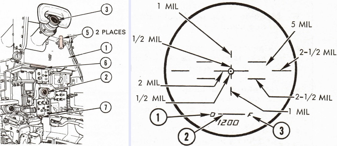
A wider view of the GPS is given on the left. The unity window had a 6° vertical field of view and a horizontal field of view of 18°, which could be increased to 30° with head movement. 1. GPS. 2. GPS periscope eyepiece. 3. Commander's optical relay extension eyepiece. 5. Armor door operating handles. 6. Unity window. 7. Magnification selection lever.
The GPS daylight reticle is drawn on the right. The current target range of 1,200m is displayed at the bottom of the sight picture. 1. Ready to fire symbol. 2. Multiple laser return symbol. 3. Malfunction symbol. (Picture from TM 9-2350-255-10-1 C3.)
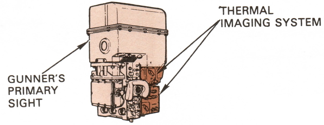
The TIS used heat sensors to detect target scene information, then converted that information to electronic signals processed by the system's electronics unit. These signals were sent to the image control unit which displayed the scene on a cathode ray tube, and this image was then projected into the GPS eyepiece. Since the TIS also used the laser rangefinder, both ballistic doors of the GPS housing had to be open when the TIS was being used. (Picture from TM 9-2350-255-10-1 C3.)
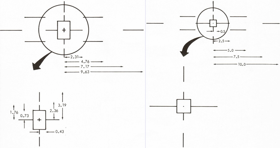
Early-production TIS assemblies used the reticle on the left with a rectangular box in the center of the pattern, while later systems used a square box as shown on the right. (Picture from TM 9-2350-255-10-1 C3.)
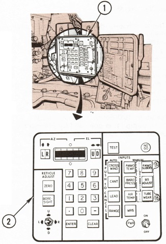
The ballistic computer was mounted to the gunner's right. 1. Ballistic computer. 2. Computer control panel. (Picture from TM 9-2350-255-10-1 C3.)
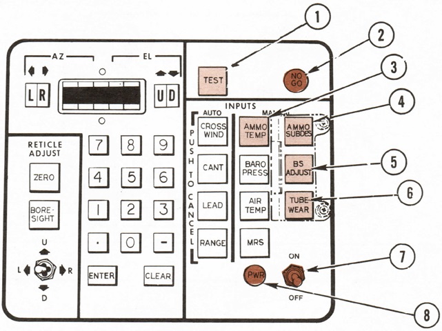
The computer control panel is detailed here. 1. TEST key. 2. NO GO light burned red if a failure occurred during a self-test and the test terminated. 3. AMMO TEMP key set the computer for manual input of ammunition temperature and showed previous data (if any). 4. AMMO SUBDES key set the computer for manual input of ammunition sub-designation code and showed previous code (if any). 5. BS ADJUST key set computer for manual input of battle sight range data and showed previous data (if any). 6. TUBE WEAR key set computer for input of tube wear data and showed previous data. 7. ON-OFF switch. 8. PWR light.
Under the AMMO TEMP key, the BARO PRESS key set the computer for manual input of barometric pressure data and showed previous data (if any). The AIR TEMP key functioned similarly for air temperature. The MRS indicator light showed if the muzzle reference sensor was set in manual adjustment of the fire control system and computer to compensate for gun tube droop. To the upper left, the CROSS WIND key canceled the automatic crosswind data, set the computer for manual input of crosswind data, and showed previous data (if any). The CANT key did the same for cant data, and the LEAD key did the same for automatic lead data. The ZERO key set the computer for input of zero corrections for the selected ammunition type. The BORE-SIGHT key set the computer for input of boresight corrections. The toggle switch in the lower left moved the GPS reticle in the desired direction during boresighting, zeroing, or MRS correction. The numbered keys were used to enter data after an input button had been pressed. The computer display was centered between the LR and UD keys that were used to indicate incoming inputs for left/right and up/down. (Picture from TM 9-2350-255-10-1 C3.)
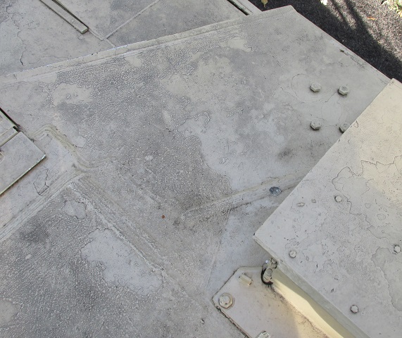
Weld lines visible on the turret roof highlight the construction of the turret shell.
A similar view is provided of the turret's right front corner.
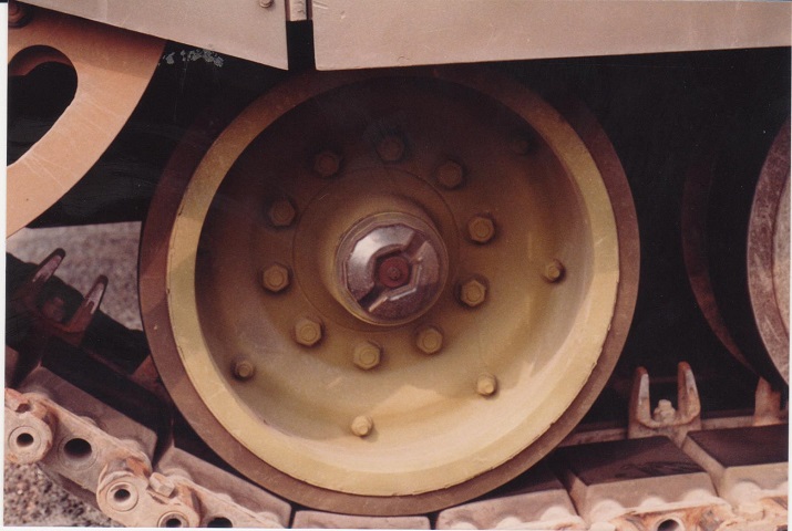
Details of the tracks and rear road wheel can be seen here. The outer hubs of the road wheels are clear plastic, which facilitates checking the lubricant level. The drive sprocket teeth can just be seen behind the track retaining ring. Note the compression of the rubber pad of the track block under the road wheel. (Photo by Richard S. Eshleman.)
A close-up of the track retaining ring is offered in this photo. During tests, tanks tended to shed tracks at the sprocket due to dirt buildup and quick turns. Fixes for this problem included the track retaining ring, increasing track tension, a mud scraper for the drive sprocket and a sprocket hub with mud chute cutouts, and steel plates welded to the hull to keep the tracks aligned and to prevent tracks from coming off to the inside. (Photo by Richard S. Eshleman.)
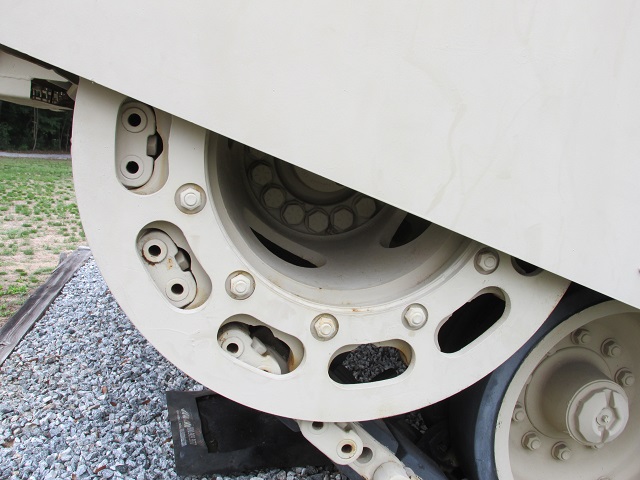
More details of the track retaining ring are provided here. The ring weighed 90lb (40kg) and was secured by eleven 30mm nuts torqued to 150-180lb-ft. The road wheel hubs have been painted on this tank.
This image highlights the evacuation holes in the drive sprocket as well as the mud scraper.
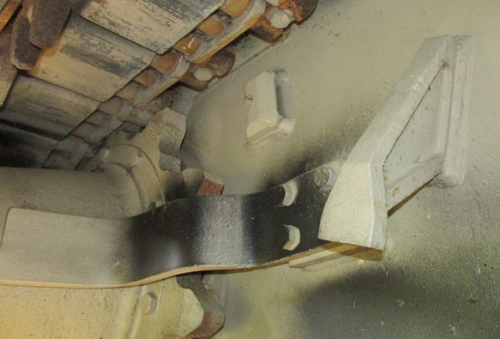
A second view of the mud scraper and one of the guidance blocks is provided here. The four 30mm bolts securing the scraper were torqued to 320-350lb-ft. The guidance block can be seen just to the inside of the track end connectors. Another guide that wraps around the rear of the final drive is hidden by the track and sprocket ring.
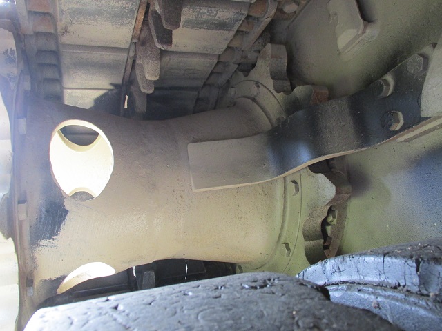
The guidance block not visible in the image above can just be seen emerging from under the rear fender.
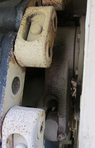
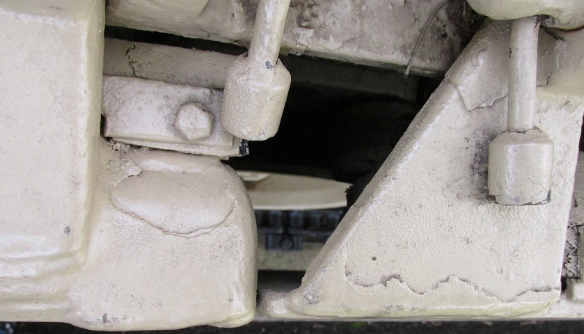
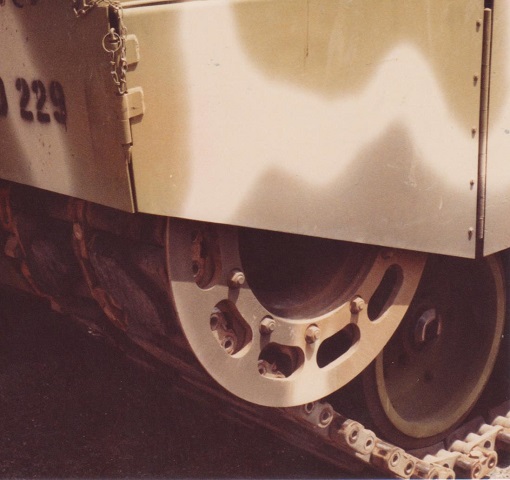
The idler wheel arm and the link connecting it to the first road wheel can be seen between the track and hull.
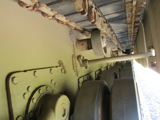
Looking forward from above the final road wheel arm, the rotary shock absorber at this position, return rollers, and skirt supports can be seen. The side hull is thickened above the forward six road wheel stations as well.
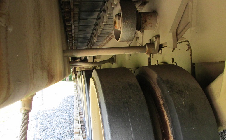
A similar view is provided from between the idler and front road wheel. The rotary shock absorber stations are larger than those of the center four undampened wheels. The increased side hull armor is easier to see in this image around the rotary shock absorber station.
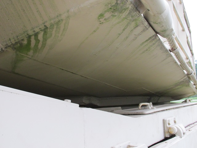
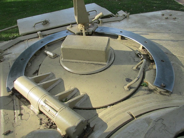
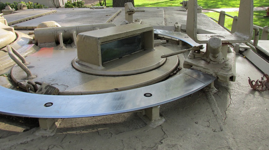
The turret ring and construction of the underside of the turret are highlighted in this image.
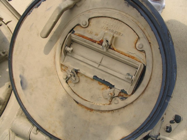
The hull ammunition stowage is illustrated in this image. The cutouts were gripped to open and close the door. 1. Door. 2. Door cutouts. 3. Back of door. 4. Cutout on back of door. 5. Door cutouts. (Picture from TM 9-2350-255-10-2 C3.)
The hull ammunition compartment featured blowoff panels on the top and bottom of the hull.
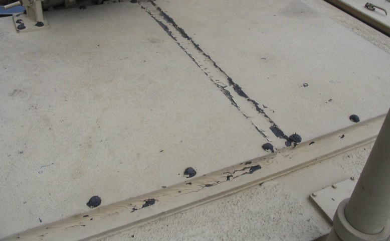
Weld lines visible on the hull floor show where the tanks' underside blowoff panels would be located.
The batteries were housed in the right rear sponson, and the covers are open here. The six 12-volt batteries powered a 24-volt electrical system. 1. Battery. 2. Clamps. 3. Plastic cover. 4. Rubber boots. 6. Cable. 8. Battery hold down. 9. Bus bars. (Picture from TM 9-2350-255-10-3 C4.)
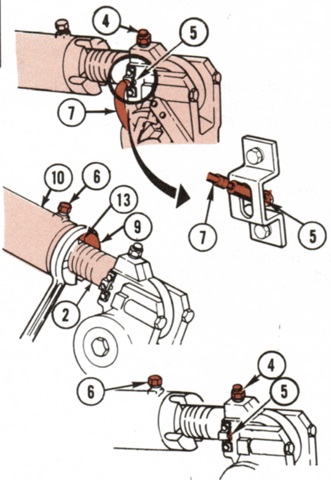
Track tension was adjusted by adding grease to the idler wheel's adjusting link until grease started to be released from the relief valve. 2. Threads. 4. Relief valve. 5. Grease fitting. 6. Lock screw. 7. Grease gun adapter. 9. Locknut. 10. Adjusting link tube. 13. Slot to line up with locknut. (Picture from TM 9-2350-255-10-3 C4.)
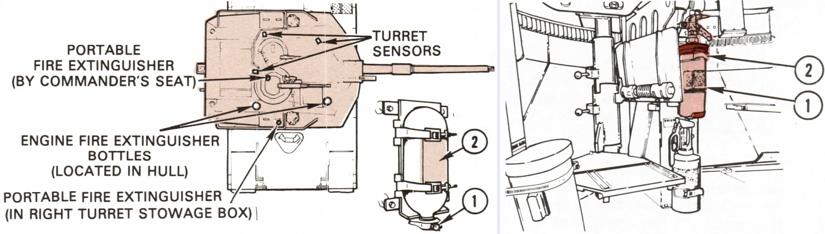
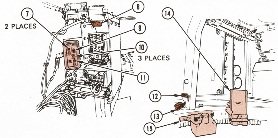
The fire extinguisher system had two bottles for the engine compartment, which discharged one at a time. These could be activated manually via handles at the driver's position and on the left rear of the hull. The crew compartment was serviced by another bottle, which could be actuated manually by another handle at the driver's position. The manual handles were to be used if the automatic detection system failed. The automatic system used seven sensors (three in the turret, one in the driver's compartment, and three in the engine compartment) to detect fires and discharge the appropriate extinguishers. The driver could activate the second engine compartment shot from his instrument panel, which would automatically shut off the engine. The outside handle was connected directly to the engine compartment second shot bottle, and did not shut down the engine when pulled. In addition, portable fire extinguishers were stowed in the right turret box and by the commander's seat.
The left image shows components of the automatic fire extinguisher system. 1. Fire bottle pressure gage. 2. Pressure versus ambient temperature chart.
The right image depicts the portable fire extinguisher by the commander's seat. 1. Portable extinguisher. 2. Rack. (Picture from TM 9-2350-255-10-1 C3 and TM 9-2350-255-10-2 C3.)
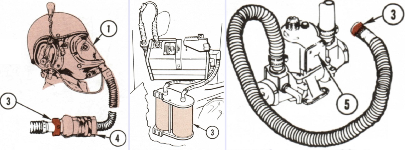
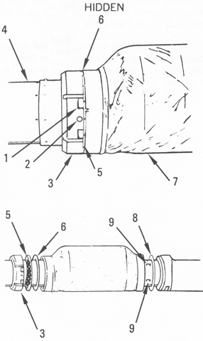
The tank was equipped with the M13A1 gas particulate filter system that provided each crewman with clean, filtered, breathable air free from toxic agents and heated to a comfortable temperature. The filter was unable to protect against carbon monoxide, however. When activated at the driver's master panel, a fan drew air into the filter housing which featured a dust separator that removed heavy particles and filters that removed fine dust and toxic gases. The air was then sent through two M18 gas filter canisters which contained activated charcoal to remove further toxins. From the M18 canisters, the air was routed to the individual crew positions where M3 heaters could heat the air before it was sent to the crewman's mask via a flexible hose. Under arctic conditions, the M3 heater was to be run for 15 minutes before connecting the masks to the air duct hoses due to the risk of cold air being blown onto the face causing frostbite. In the left image, the mask (1), air duct hose socket (3) and mask canister (4) are shown. The filter housing connected to the two M18 filter canisters (3) is depicted in the center image. On the right is the flexible hose showing the air duct hose socket (3) and the M3 heater (5). (Picture from TM 9-2350-255-10-1 C3 and TM 9-2350-255-10-2 C3.)
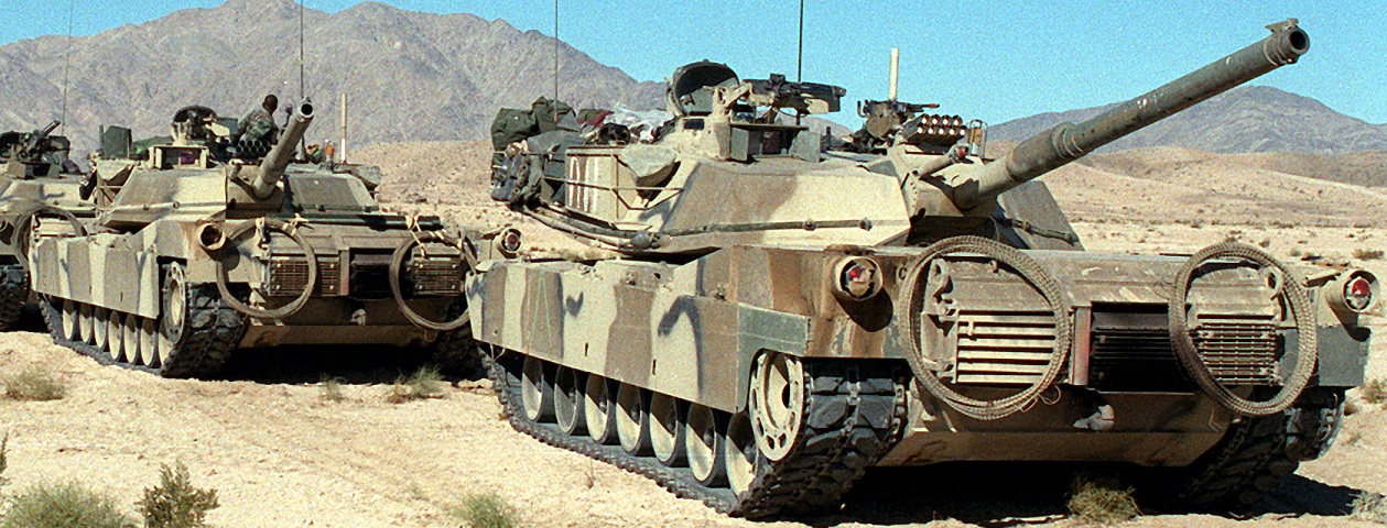
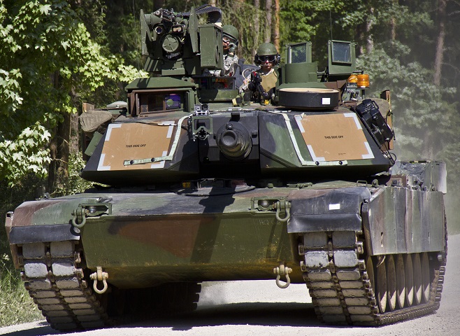
With increased protection, the shape of the turret front and gun mantlet on these tanks is subtly different from the earlier tanks above. Note that the aperture for the gunner's auxiliary telescope is no longer totally contained by the gun mantlet armor. The detachable stowage rack introduced on the IPM1 can be contrasted with the original bustle tie-downs on the tank at the top of the page. These 24th Infantry Division (Mechanized) tanks were participating in NATO Exercise Display Determination '87; pyrotechnics have been mounted on the bore evacuator to simulate the main gun firing, and the machine guns have blank adapters fitted. (Picture taken 1 Jan 1987 by MSG William B. Belcher; available from the Defense Visual Information Center.)
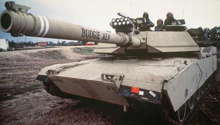
Another view of the enhanced turret front is provided here. The mounting lug on top of the gun mantlet no longer extends straight out, but rises upward to the horizontal section. The "Boogie Men" were 24th Infantry Division (Mechanized) tankers who were participating in NATO Exercise Display Determination '87. (Picture taken 1 Jan 1987 by MSG William B. Belcher; available from the National Archives.)
The near tank has the redesigned rear skirt, while the rear skirt section has simply been removed from the machine in the background. They both still have the track retaining rings on the drive sprockets, however. These tanks belonged to the 24th Infantry Division (Mechanized) and were taking part in an exercise; MILES sensors are attached to the turrets, and pyrotechnics are mounted on the gun mantlet. (Picture taken 1 Nov 1988; available from the National Archives.)

A closer look at the tank's turret front shows a bit more detail about the changed shape. (Picture taken 1 Nov 1988; available from the National Archives.)
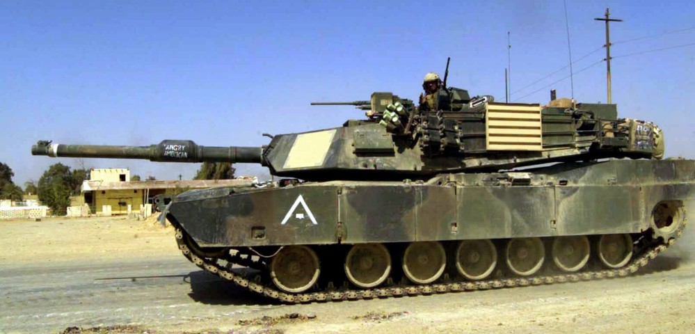
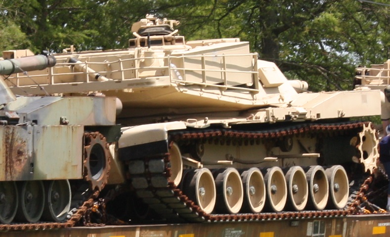
The larger main gun marks this vehicle as an M1A1. The vent for the overpressure NBC system can be seen above the number 5 track skirt. The M250 smoke grenade launcher on each side of the turret was replaced by the US Marines by two 4-barrel M257 launchers, which were able to utilize the M76 infrared screening grenade. An external auxiliary power unit is visible in the turret bustle stowage basket. (Picture taken 1 Apr 2003 by CPL Mace M. Gratz; available from the Defense Visual Information Center.)
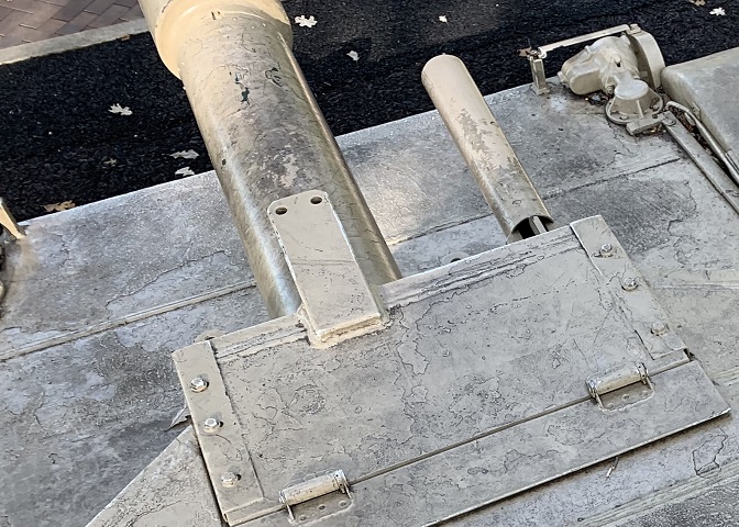
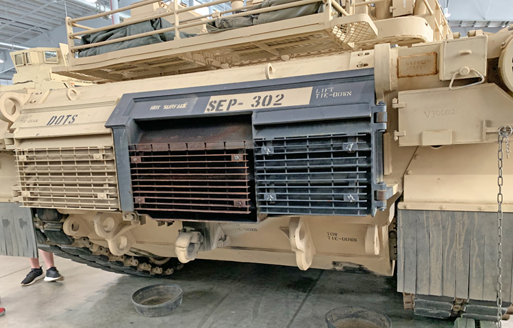
The discolored grille on the rear hull of this tank is the engine exhaust, and visible surrounding it is a mounting bracket with holes for attaching a fording stack. The other two grilles are for engine and transmission oil cooling. The tank commander is CPT William T. Cundy. (Picture taken 13 Nov 2003 by TSGT John L. Houghton, Jr.; available from the Defense Visual Information Center.)
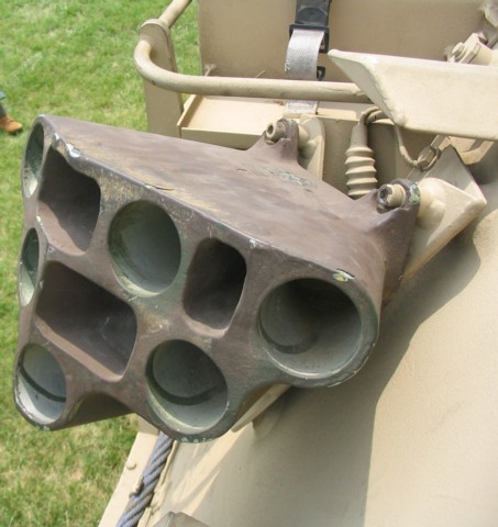
The M250 smoke grenade launcher is isolated in this picture.
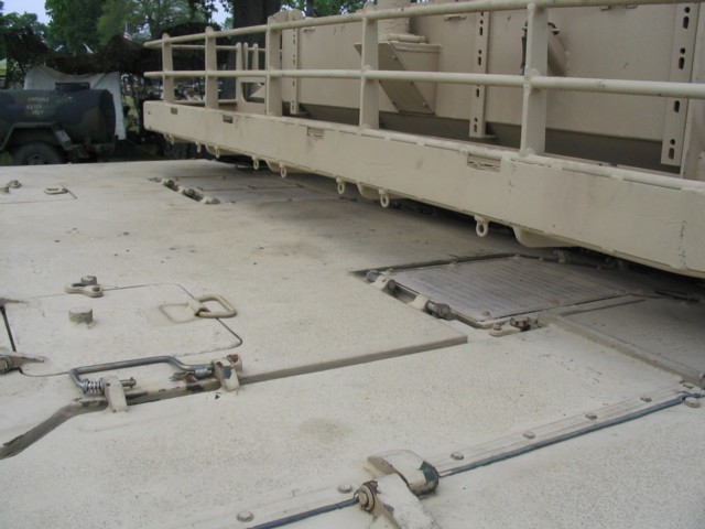
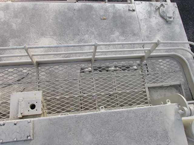
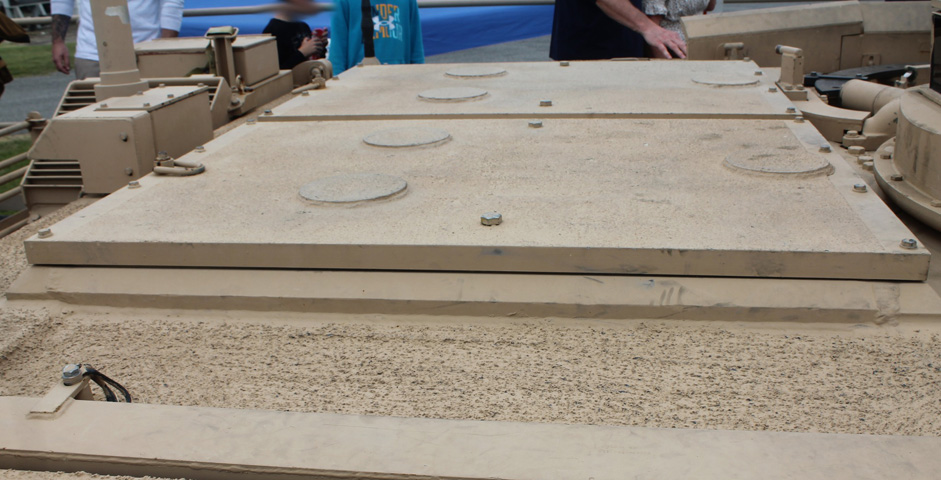
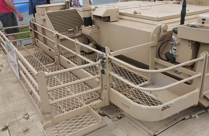
The rear deck of the M1A1 features engine air inlet grilles and various access hatches.
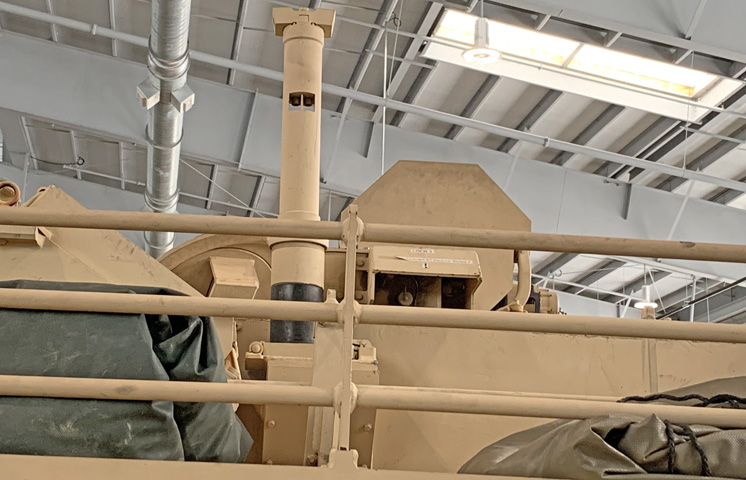
The turret bustle features blowoff panels over the ammunition stowage, so that if an ammunition explosion occurs, the energy and gases will be dispersed into the atmosphere instead of into the crew compartment. The tank's crosswind sensor is visible in the lower right corner of this picture.
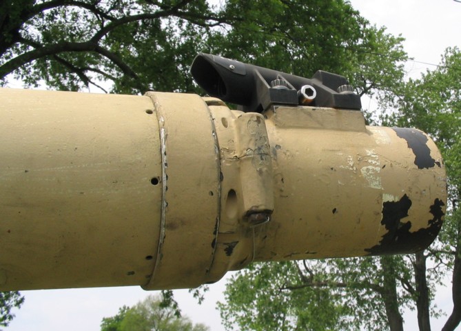
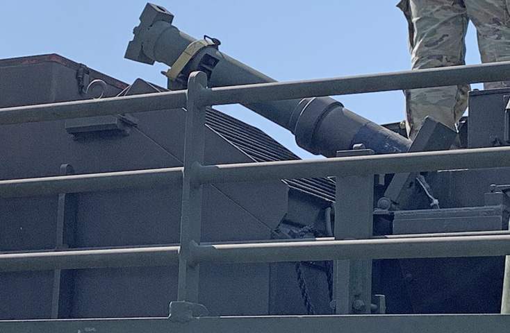
The device on the end of the gun tube is part of the vehicle's muzzle reference system. This allows the gunner and ballistic computer to account for artificial boresight loss. The thermal shroud on the barrel was intended to help alleviate droop caused by uneven heating.
A more detailed view of the muzzle reference sensor is given in this sketch. 1. Muzzle reference sensor. 2. Tritium cell. 3. Lens. 4. Lens. (Picture from Army TM 9-2350-264-10-2 C11 Marine Corps TM 08953A-10/1-2 C11.)
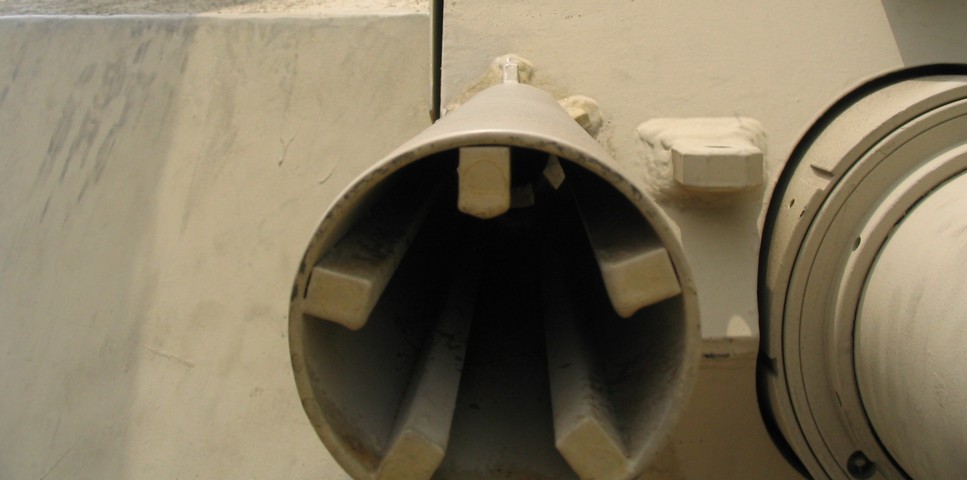
The bore evacuator for the 120mm gun was noticeably larger than that for the 105mm gun. 1. Screw. 2. Plunger. 3. Evacuator nut. 4. Thermal shroud. 5. Retainer. 6. Packing. 7. Bore evacuator. 8. Packing. 9. Gas ports. (Picture from Army TM 9-2350-264-10-2 C11 Marine Corps TM 08953A-10/1-2 C11.)
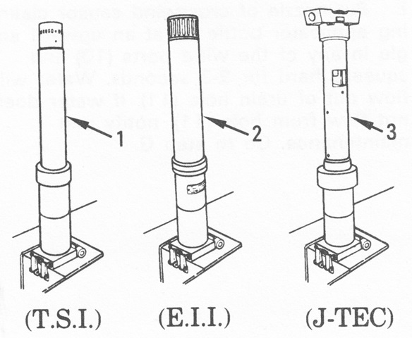
The crosswind sensor on the turret rear could be one of three types, as shown. (Picture from Army TM 9-2350-264-10-2 C11 Marine Corps TM 08953A-10/1-2 C11.)
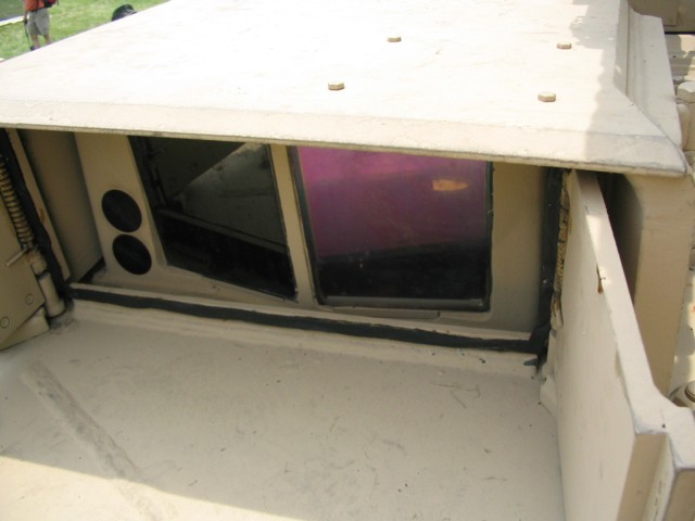
The shutters of the gunner's primary sight doghouse are open in this view. Note the difference in construction versus the one pictured above.
The coaxial machine gun on the Abrams was provided with a flash-suppressing barrel shroud.
The loader was provided with a hatch in the turret roof across from the TC, and a periscope was installed in his hatch door.
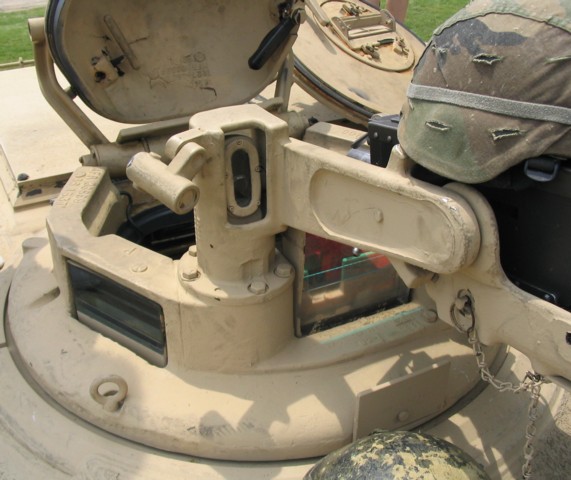
The TC's position was ringed with six vision blocks, as well as the 3x sight for the .50cal machine gun. The cupola hatch door could also be positioned so that it provided overhead protection while still allowing the TC outside vision.
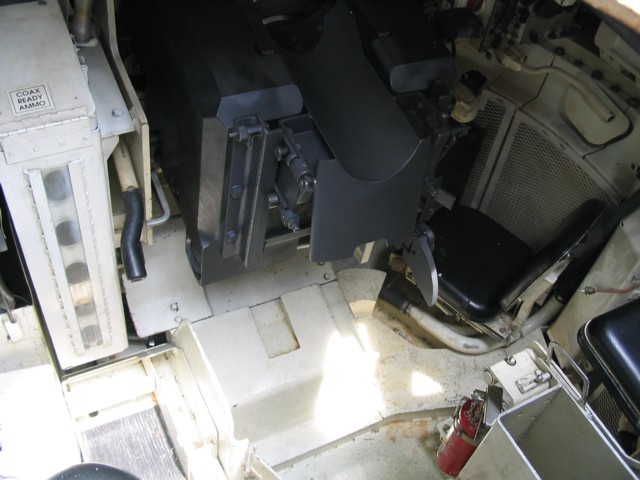
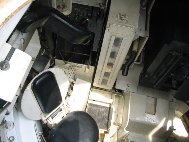
This view into the turret shows the gunner's seat, and just to its left, the breech for the 120mm main gun. The loader's black-handled safe/armed lever is to the guns left. The gunner was provided with a chest support, and it is folded away to the right. The coaxial machine gun's ready ammunition box is labeled, and the belt of ammo would snake across the top of the main gun's breech. The stub base deflector for the 120mm ammunition is in place on the breechblock; when the safe/armed lever was moved to the safe position, the deflector would drop down on top of the breechblock to facilitate loading.
The 120mm gun travel lock is sketched in use on the left and stowed on the right. It operated similarly to that found in 105mm gun tanks, except that it was folded onto the gun instead of the roof for stowage. Lockarms could be found with either two or three holes. For thee-hole arms, the center hole was used for stowing the arm, but the top hole of both types was used for securing the gun. 1. Gun travel lock. 2. Button. 3. Lockpin. 4. Roof bracket. 5. Main gun bracket. (Picture from Army TM 9-2350-264-10-1 Marine Corps TM 08953A-10/1-1.)
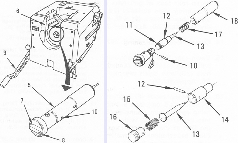
The firing mechanism for the 120mm gun is diagrammed in these images. In order to remove the firing mechanism assembly, the lever was turned until the mark was at the 2:00 position. 5. Firing mechanism assembly. 6. Breechblock. 7. Lever. 8. Mark. 9. Operating handle. 10. Straight pin. 11. Firing pin assembly. 12. Straight pin. 13. Firing pin. 14. Guide. 15. Spring. 16. Cap. 17. Spring. 18. Housing. (Picture from Army TM 9-2350-264-10-2 C11 Marine Corps TM 08953A-10/1-2 C11.)
The opposite side of the turret interior is shown here. The loader's seat is visible, as is the vehicle's radio setup behind the padded shoulder guard. When in action, the shoulder guard would be swung down to protect the loader from the recoil of the main gun. Below the radio is stowage for field boxes of 7.62mm ammunition.
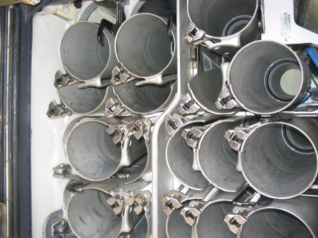
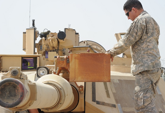
The ready rack of 120mm ammunition is shown here. The turret bustle ammunition is placed behind blast doors, so that if there is an ammunition detonation, the roof blowoff panels will vent the blast away from the crew compartment. There is a semi-ready rack behind the commander's position, and rounds are transferred to the ready rack as it is depleted and as time allows.
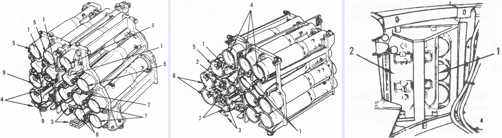
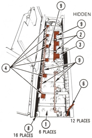
Initially, the 120mm ammunition was stowed in two 16-round racks in the turret bustle as well as a 6-round rack in the hull. The turret ready rack is shown on the left. Numbers 5-9 are swing tubes that were moved out of the way and locked after loading, and could be released into the loading position by pulling levers numbered 1-4. The rack for the turret stowage compartment behind the commander is in the center. Swing tubes for this rack are labeled 4-7, and their release levers are 1-3. The hull rack is shown on the right. It was covered by two doors, right (1) and left (2), only one of which at a time could be open. The right door is shown ajar. (Picture from Army TM 9-2350-264-10-1 Marine Corps TM 08953A-10/1-1.)
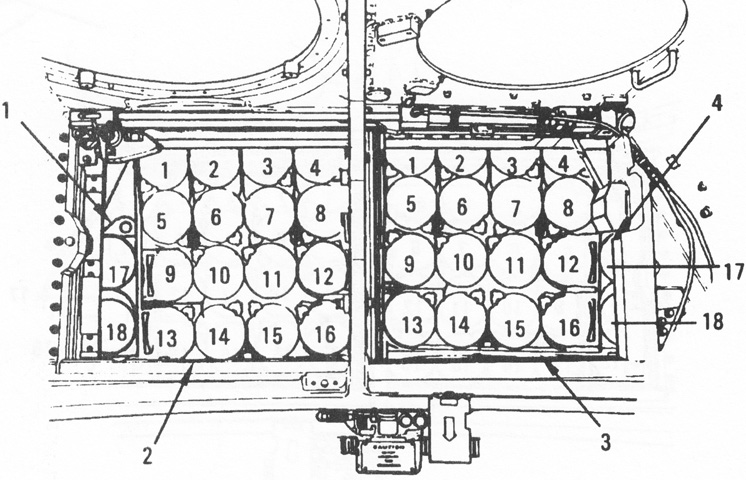
Turret ammunition stowage was redesigned, allowing an extra round to be carried in both the stowage ammunition compartment (2) and the ready ammunition compartment (3). A two-round rack (1) was installed on the outboard side of each compartment. Tubes 1-4 and 17-18 on each side were swing tubes. (Picture from Army TM 9-2350-264-10-1 Marine Corps TM 08953A-10/1-1.)
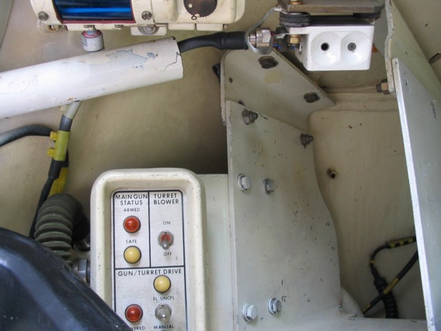
The loader's control panel is shown here, and would give indications of the main gun's status as well as operate the turret ventilation blower and turret drive. A blue night light is visible towards the top of the image.
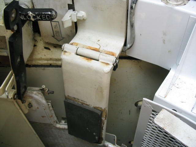
The bustle ammunition blast doors were operated by this padded kneeswitch. Once the ready rack door reached its final half inch (1.3cm) of closing travel, it could not be stopped.
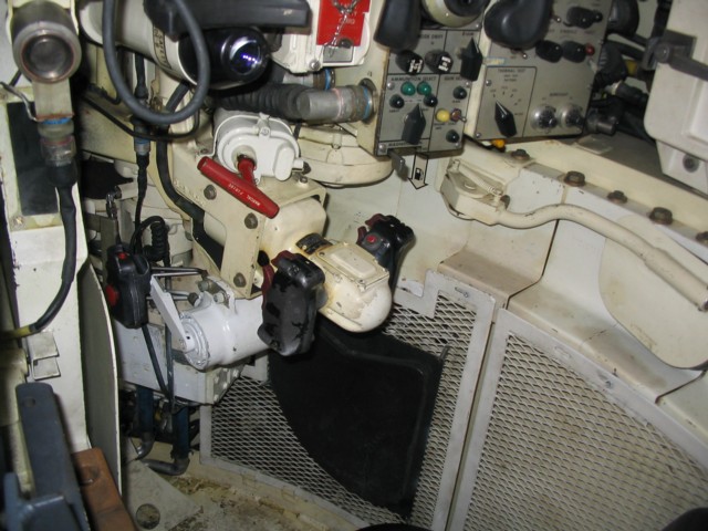
A look at the gunner's position is provided here. The chest support is folded out of the way, and a kneepad is provided on the turret basket. The red handle is the main gun's manual firing handle, and just above that is the gunner's auxiliary sighting telescope.
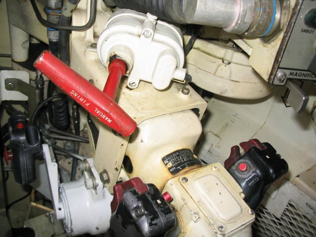
This image provides a close look at the gunner's control cadillacs. The large switches on the front of the handles are the palm switches to engage the tank's stabilization system, the thumb buttons are for firing the laser rangefinder, and the index triggers are for firing the weapons.
The gunner's control panel is shown here. His primary sight and its browpad can be seen at the top of the picture.

Reticles for a later-production gunner's auxiliary sight are drawn above. Kinetic energy penetrators and the XM943 STAFF round were bundled together on one reticle (6), and HEAT and MPAT were on the other (7). The numbers indicated hundreds of meters, and the first horizontal segment to either side of the vertical center line represented the lead necessary for a target at 1,000m (1,090yd) traveling at 10mph (16kph). The second segment to either side of the vertical line marked the lead necessary for a target at 1,000m (1,090yd) going 20mph (32kph). Zero points were marked at 1,200m for KE, 800-1,200m for STAFF, and 1,200m for both MPAT and HEAT. When the stadiametric rangefinder was included, the dashed line was used for estimating the range of full tank-height targets, while the dotted line was used for hull-down targets. (Picture from Army TM 9-2350-264-10-1 Marine Corps TM 08953A-10/1-1.)
The TC was able to see what the gunner was looking at via the gunner's primary sight extension. The gunner's controls are visible low in the background, and above those are the handles that open and close the armored shutters for the gunner's primary sight.
The .50cal machine gun cupola was elevated manually with this handwheel, and the red trigger fired the weapon.
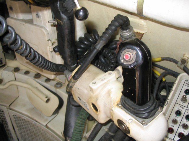
The tank commander was provided with a turret control handle as well, and could override the gunner's inputs if necessary. The TC's override was equipped with triggers for the laser rangefinder and weapons, so the TC could fight the tank if the need arose. The black handle in front of the turret control handle was for the powered traverse of the commander's cupola, and the handle with the black knob allowed the commander to switch between powered and manual traverse of the cupola. The gunner's chest support is visible near the bottom of the picture.
The TC's control panel is shown in this image.

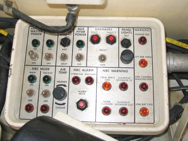
The commander's panel was later upgraded to the design above. 1. Smoke grenade ready pushbutton. 2. Smoke grenade salvo 1 pushbutton. 3. Smoke grenade salvo 2 pushbutton. 4. Panel lights test pushbutton. 5. Panel lights brightness controls. 6. Engine fire warning light. 7. Turret networks box circuit breaker open warning light. 8. Fire control system malfunction warning light. 9. Low battery warning light.
Unlabeled, the top row of pushbuttons controlled the master electrical power, turret electrical power (which also turned on vehicle master power), and the auxiliary hydraulic system. The buttons in the row below these were for using battlesight range, the NBC system main mode, the NBC system backup mode, and muting NBC alarms. The buttons below the battlesight button manually adjusted range after the battlesight button was pressed. The air temperature buttons controlled the temperature of filtered air. To the right of the AIR TEMP panel were warning lights for, clockwise from upper left, clogged NBC filters, an unpressurized crew compartment, air temperature to the NBC filter being too high, and bleed air temperature from the precooler being too high. At the bottom right were warning lights for, clockwise from upper left, NBC main mode off, NBC main mode on, NBC backup mode off, NBC backup mode on, nuclear radiation detection, and chemical agent detection. (Picture from Army TM 9-2350-264-10-1 Marine Corps TM 08953A-10/1-1.)
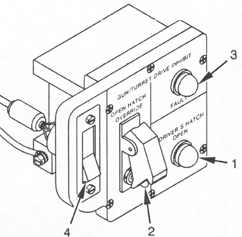
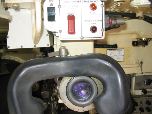
A driver's hatch interlock prevented the gun/turret drive system from operating when the driver's hatch was open. The commander was provided with an alert panel that indicated when the driver's hatch was open or faults existed in the gun/turret drive inhibit system; this panel also contained a switch to override this interlock in emergencies. 1. Driver's hatch open light. 2. Open hatch override switch. 3. Gun/turret drive inhibit fault light. 4. Radio/intercom switch. (Picture from Army TM 9-2350-264-10-1 Marine Corps TM 08953A-10/1-1.)
The driver's instrument panel is shown here.
The driver's master panel is on his right side.
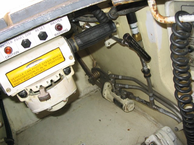
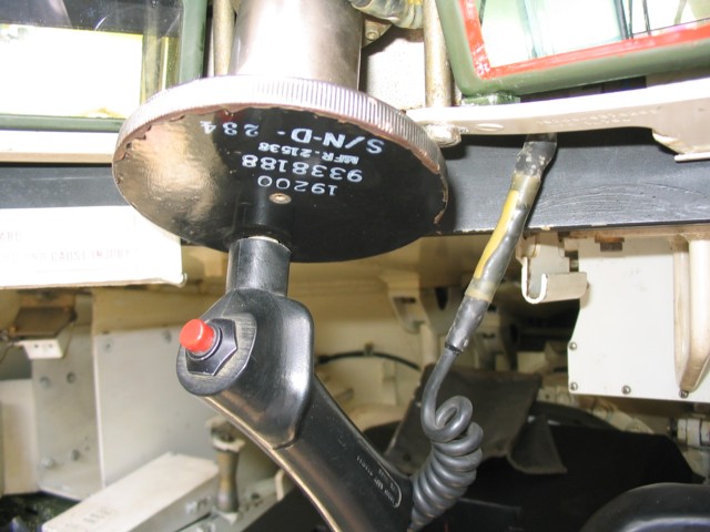
The driver controlled throttle and steering with a motorcycle-style T-bar. Throttle was controlled by twisting the handle, and therefore an accelerator pedal was not needed. The transmission selector is placed below the T-bar, and the black parking brake release handle is to the driver's right.
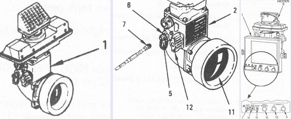
The driver's image intensifying night vision viewer is shown in the left and center images, while the newer thermal driver's vision enhancer (DVE) is on the right. Both were installed in the driver's hatch in place of the center periscope. The legend for the left and center drawings is: 1. Night vision viewer. 2. Night vision viewer. 5. Cap. 6. Plug. 7. Connector. 11. Screen. 12. OFF-BRIGHT knob. The legend for the right-side drawing is: 1. DVE. 7. Power switch. 9. Azimuth and elevation controls. 10. Sensor level control. 11. Sensor gain control. 12. Display brightness knob. 13. Polarity switch. 14. Video switch. (Picture from Army TM 9-2350-264-10-1 Marine Corps TM 08953A-10/1-1.)
The track adjusting link could also be an unthreaded design. It is sketched here with the grease pump attached. 1. Track adjusting link. 4. Shaft. 5. Relief valve. 6. Grease fitting. 7. Adapter. (Picture from Army TM 9-2350-264-10-2 C11 Marine Corps TM 08953A-10/1-2 C11.)

The pulse jet system applied scheduled bursts of high-pressure air to the inside of each engine air cleaner (V-pack) to blow out dust and other accumulations. Each V-pack was serviced by three pulse control valves. The system was charged to ~200psi (14kg/cm²) using bleed air from the engine, and the pulse jet system activated when engine speed exceeded 1,485rpm and deactivated when the engine dropped to below 1,410rpm. In low clean mode, the pulse control unit actuated the nine pulse control valves three times at 10-second intervals, then monitored for flow restrictions for ~15.5 minutes, when the cycle was repeated. If an obstruction was detected, the system entered high clean mode, pulsing the jets continually until the restriction was removed, or if an unclearable obstruction was present the clogged air cleaner filter warning light on the driver's instrument panel would illuminate. 1. V-pack. 2. Pulse control valves. 4. Pulse control unit. (Picture from Army TM 9-2350-264-10-1 Marine Corps TM 08953A-10/1-1.)
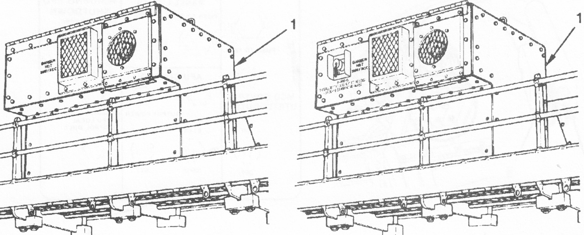
Two versions of the bustle-mounted EAPU are drawn above. The one on the left contained an internal battery and could be started electrically from either the tank's batteries or its own battery, or manually by a pull cable. The version on the right lacked an internal battery, but had a NATO connector that was used as a utility outlet. The EAPU provided 24 volt DC power to the tank in order to run systems and charge the tank's and its own batteries. The EAPU was powered by a single-cylinder, four-cycle, naturally-aspirated, air-cooled diesel engine that drove a generator with a V-belt and pulleys. It could run for around 8 hours on its own fuel tank. (Picture from Army TM 9-2350-264-10-1 Marine Corps TM 08953A-10/1-1.)
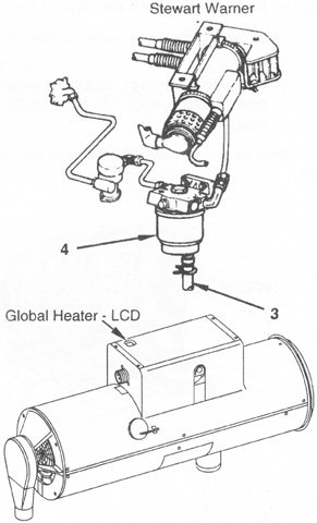
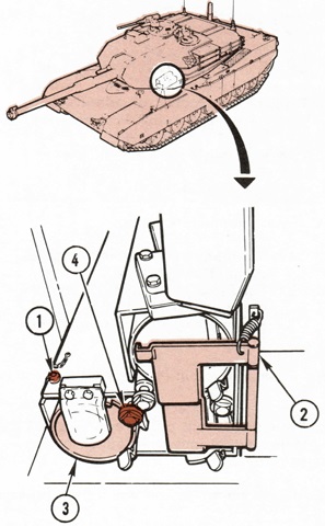
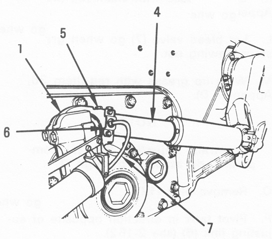
Personnel heaters could be manufactured by either Stewart-Warner or Global Industrial, drawn respectively at the top and bottom above. The Global product had an LCD troubleshooting display window on its cover. The Stewart-Warner could overheat and enter a shutdown cycle when the crew compartment temperature was 80°F (27°C) or more. 3. Drain valve. 4. Fuel/water separator. (Picture from Army TM 9-2350-264-10-1 Marine Corps TM 08953A-10/1-1.)
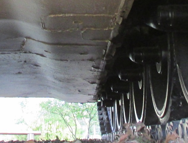
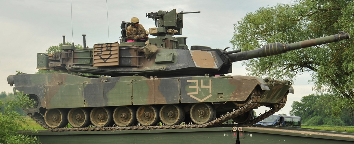
The armored skirts have been removed from this tank, allowing a view of the return rollers and supports for the skirts attached to the lower hull side. Note the damage to the skirt on the tank to the left. (Photo by Richard S. Eshleman.)
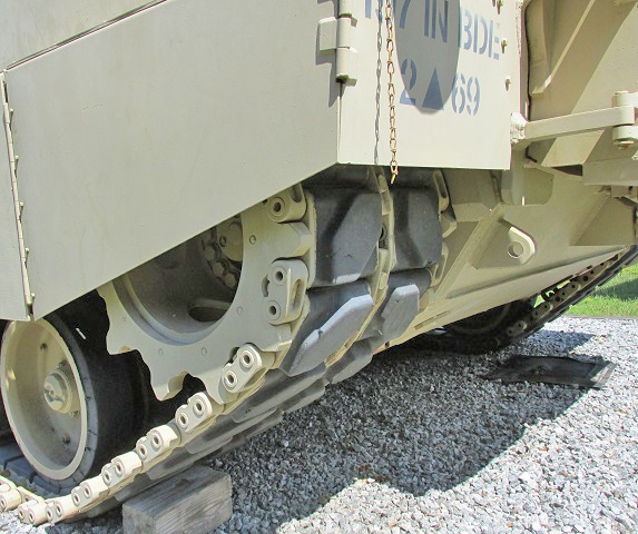
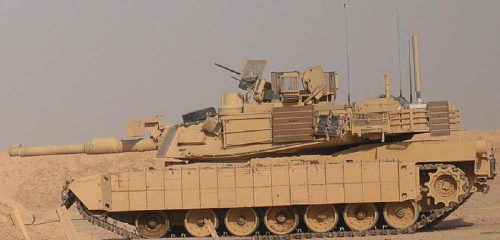
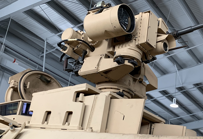
This tank is fitted with several features from the TUSK I upgrade kit. Present are the shields for the TC and loader as well as the TC's thermal .50cal sight, the mount for a .50cal MG over the gun mantlet (the Counter Sniper/Antimaterial Mount; CSAMM), explosive reactive armor tiles on the side skirts, and the V-shaped armor applique on the hull bottom. This tank belonged to Delta Company, 3rd Battalion, 69th Armored Regiment, 1st Brigade, 3rd Infantry Division, and was being used to train Iraqi tankers in Joint Security Station Al Rashid, Iraq. The box with the pyramidal top attached to the gunner's primary sight housing is the antenna for the Blue Force Tracker system. (Picture taken 15 Jul 2010 by SPC Gary Silverman; available from the Defense Video & Imagery Distribution System.)
A better view of the CSAMM mount and its attachment to the gun mantlet is provided here. This tank has also been fitted with the TC's and loader's shields and the TC's thermal sight on his .50cal mount. In this image, SGT Anthony Ciofalo of Delta Company, 3rd Battalion, 69th Armored Regiment, 1st Brigade, 3rd Infantry Division is instructing an Iraqi soldier on driving the tank in Joint Security Station Al Rashid. (Picture taken 15 Jul 2010 by SPC Gary Silverman; available from the Defense Video & Imagery Distribution System.)
The commander's independent thermal viewer can be seen in front of the loader's position on this vehicle, and it is aimed to the tank's right. A tow bar is stowed on the tank's bow. (Picture taken 26 Jan 2006 by SSG Aaron D. Allmon, II; available from the Defense Visual Information Center.)
Features of the TUSK kit present on this tank include explosive reactive armor tiles on the side skirts, shields around the loader's and TC's position, and the CSAMM mount. The .50cal MG has a front shield as well as the armor enclosing the sides and rear. The large antenna at the rear of the turret bustle is part of the AN/ULQ-35 Counter Remote Controlled Improvised Explosive Device (RCIED) Electronic Warfare (CREW) Duke IED jammer system. This tank belonged to Company D, 1st Battalion, 5th Cavalry Regiment, 2nd Advise and Assist Brigade, 1st Cavalry Division, and was training on Memorial Range near Contingency Operating Base Speicher. (Picture taken 27 Jul 2011 by SGT Quentin Johnson; available from the Defense Video & Imagery Distribution System.)
Further details of the shielding around the TC's position can be seen here. These men were with Troop A, 1st Squadron, 3rd Armored Cavalry Regiment, and were training on the Besmaya Combat Training Center range near Baghdad. (Picture taken 9 Jan 2011 by SSG Garrett Ralston; available from the Defense Video & Imagery Distribution System.)
The very tall common remotely operated weapon system (CROWS) has been mounted on this tank. It provides the commander with a thermal viewer, laser rangefinder, and a mount for the .50cal machine gun that can be operated from under armor. The loader's MG is not present, but he has been provided with armored shields. Instead, he is wielding a carbine with a blank adapter. The TC is LTC Carter Price, commander of 2d Battalion, 5th Cavalry Regiment, 1st Brigade Combat Team, 1st Cavalry Division. They were taking part in Operation Combined Resolve II. (Picture taken 25 May 2014 by PFC Daniel Lograsso; available from the Defense Video & Imagery Distribution System.)
The mount of the CROWS encompasses the gunner's primary sight enclosure. Forward vision for the TC is affected, as can be seen here. The T-shaped antenna to the crosswind sensor's right in the turret bustle rack was for the CREW IED jammer system. The green box with the light top in front of the CREW antenna is the antenna for the Blue Force Tracker system. This tank belongs to D Company, 3rd Battalion, 69th Armor Regiment, 1st Armor Brigade Combat Team, 3rd Infantry Division and was taking part in exercise Heidesturm Shock. (Picture taken 6 Jun 2015 by Markus Rauchenberger; available from the Defense Video & Imagery Distribution System.)
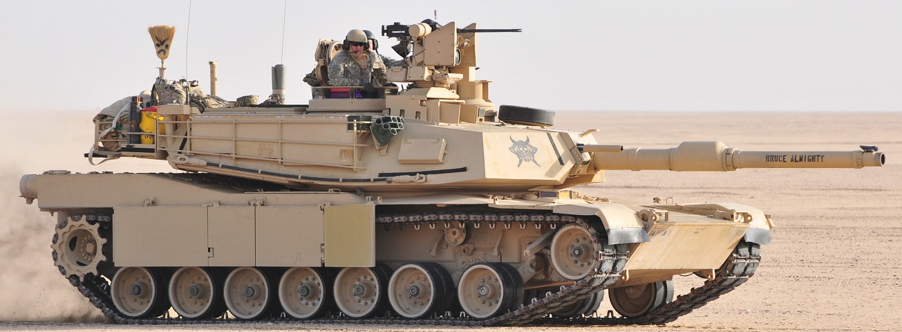
"Bruce Almighty" provides us with a rare view of the suspension without the full set of side skirts. The front return roller can be seen. (Picture taken 6 Dec 2016 by SGT Aaron Ellerman; available from the Defense Video & Imagery Distribution System.)
The CROWS-LP on this tank provides a stark contrast to the earlier, taller versions above. The CITV is rotated to the rear. The loader's armored gun shield is installed at his position, but the commander's shields have not been mounted. Differences in the turret front geometry and thickness can be ascertained especially by the triangular notches at the bottom corners of the gun mount opening.
The new geometry of the notches in the turret face can better be seen from this angle. Note the lip that has been added around the driver's hatch.
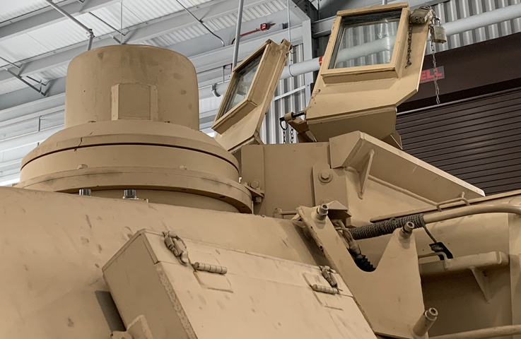
The redesigned CROWS presented a lower height in front of the commander's station. The smoke grenade launchers are not mounted on this tank, but their mounting brackets remain, along with the smoke grenade stowage box. The brackets welded along the turret side were for installation of ARAT 2 reactive armor tiles.
The shape and size of the right front corner of the turret is shown here. Mounting points for ARAT 2, the smoke grenade stowage box, and the tow cable release are found on this plate.
The underside of the turret's right front corner is seen in this image.
The driver's hatch is open, and a fuel filler cover can be seen under the turret. Wiring conduit runs behind the driver's hatch to the right front corner of the hull, where a directional ultra-low profile broadband antenna could be mounted.
The armor around the gun mount is shown here, along with the coaxial machine gun's flash hider and the semicircular aperture for the gunner's auxiliary sight in the lower right corner of the gun shield.
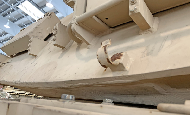
The towing eyes on the front hull were massively reinforced compared to earlier types.
The CROWS-LP was installed over the gunner's primary sight housing in a similar manner to the older CROWS assemblies.
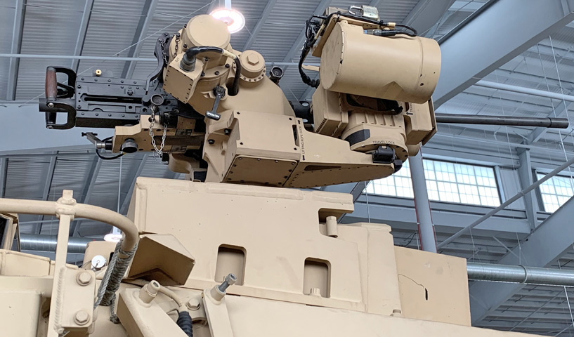
Further details of the CROWS-LP installation can be seen in this image. The sights and laser rangefinder were found on the side of the unit rather than underneath, as on the earlier M153 CROWS II.
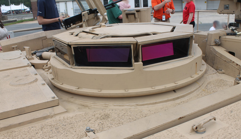
The new commander's cupola design can be compared with the older ones above. Note that there is no machine gun mount on the cupola now that the remote weapon system has been added. (Photo by Richard S. Eshleman.)
The turret bustle ammunition blowoff panels are highlighted in this image. The fence of the loader's armor kit is visible on the opposite side of the turret roof. (Photo by Richard S. Eshleman.)
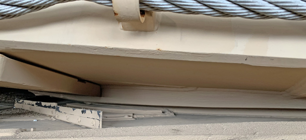
The right-side hull roof and bottom of the turret side are seen in this image.
The bottom of the turret bustle's right side can be seen in this image.
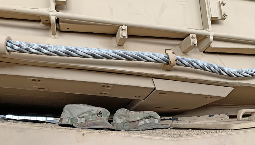
The right corner of the turret bustle stowage basket is shown here. The horizontal box above the stowage rack with the vertical conduit leading down is the satellite transceiver for the Blue Force Tracker system. A radio antenna mount is just inboard of this transceiver.
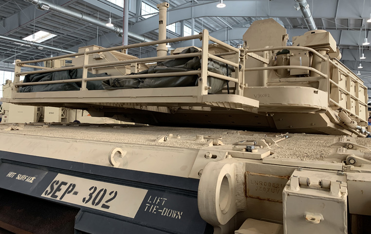
A wider view of the turret rear reveals the crosswind sensor and the sloping louvres of thermal management system at the opposite corner of the stowage rack.
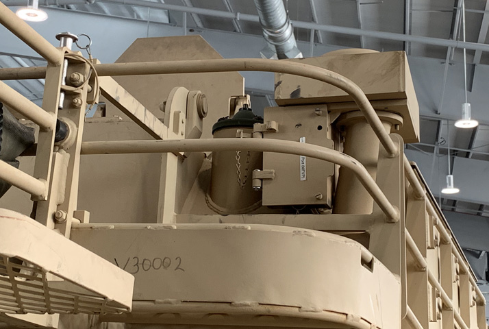
The tank's J-TEC crosswind sensor is in place, and the sloping thermal management unit is visible behind the tarp to the left of the crosswind sensor. The housing on the turret roof to the right of the crosswind sensor was part of the installation for the CREW 3 system, which would take up the majority of the space in the rear stowage basket when present.
The turret bustle stowage basket is detailed in this picture. The thermal management system can be seen on the opposite side beyond the crosswind sensor, and the transceiver for the Blue Force Tracker system is visible at the right of the image. (Photo by Richard S. Eshleman.)
The hinge on the wind sensor has been reversed from its original orientation, and it now is secured to the thermal management system when stowed.
The rear grille doors dominate the rear of the hull. The tank infantry phone box can be seen at the right of the image. Note the strengthened towing eyes to each side of the central towing pintle.
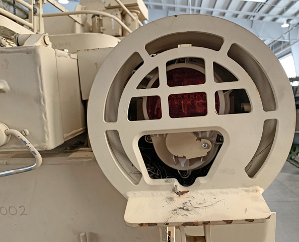
The right taillight incorporated a thermal camera assembly to give the driver a rearward view. Additional shielding around the camera was installed.
The cover for the taillight camera assembly is open on this tank. (Photo by Richard S. Eshleman.)
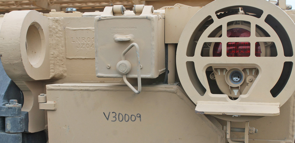
The under-armor auxiliary power unit was installed in the left rear sponson, and its exhaust was given an armored outlet below the left taillight. Note the lack of shielding on this taillight compared to the right one with its thermal camera.
The vent for the NBC system remained in the hull left side, and the engine's mesh-covered air intake port is visible at the left rear corner of the hull top. Mounting blocks for ARAT 2 tile mounting plates are attached to the vertical supports of the stowage basket.
A closer view of the engine air intake and the hull roof above the NBC system vent is provided here.
Details of the side and underside of the turret are shown here, along with the ARAT 2 mounting points.
The loader's transparent armor assemblies and the fence around his position are seen here along with the CITV. The empty smoke grenade launcher bracket and the smoke grenade stowage box are visible on the turret side.
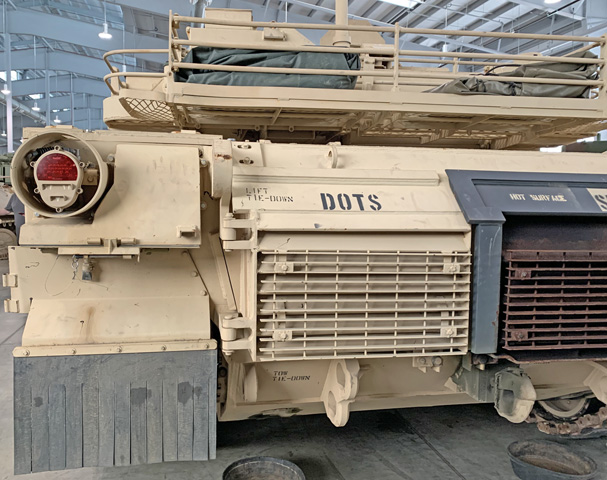
The loader's side of the turret is shown from the rear. The thermal management system is in the stowage basket, and the fence around the outboard side of the loader's position can be better seen. The auxiliary power unit access door has a "HOT SURFACE" warning stenciled on it, and the engine's air intake is easily seen from above. (Photo by Richard S. Eshleman.)
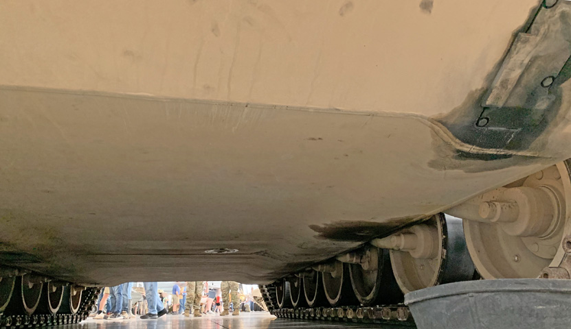
The hull bottom presented relatively few openings for access or draining compared to earlier tanks.
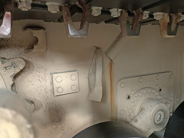
The mud scrapers are not present on this tank, but the right-hand mounting pad is shown here. The housing for the rear rotary shock absorber is also in view.
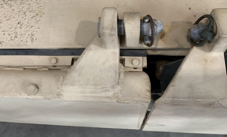
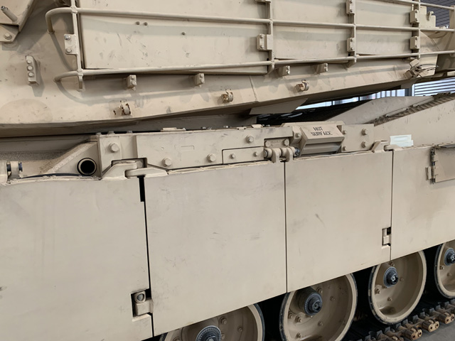
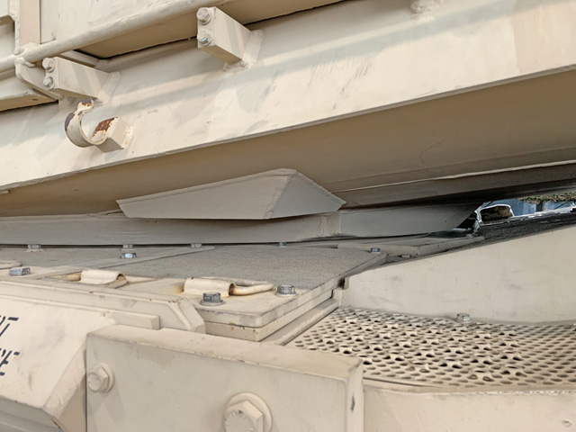
The thickness of the ballistic skirt on the left can be compared with the skirt on the right that is not composed of special armor.
