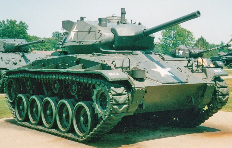
Light Tank M24 Chaffee at the Patton Museum of Cavalry and Armor.
The toylike appearance of the M24 is deceiving; this was the most heavily-armed light tank of the Second World War. The large steering assembly access hatch is apparent in the hull front, and the torsion bar suspension was a first for American light tanks. The opening in the underside of the gun shield to the 75mm gun's right was for the coaxial machine gun; the gunner's telescope was mounted on the opposite side of the 75mm gun. The tracks on this tank are the T85E1 double-pin type.
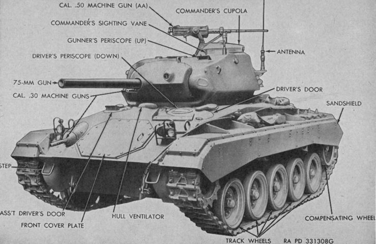
This front three-quarters view illustrates standard stowage. (Picture from TM 9-729 Light Tank M24.)
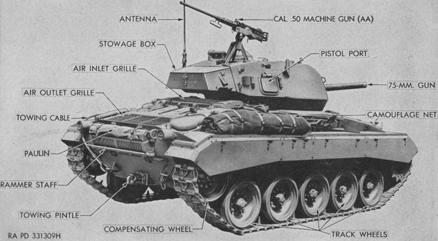
The rear of the vehicle and its stowage is shown in this picture. (Picture from TM 9-729 Light Tank M24.)
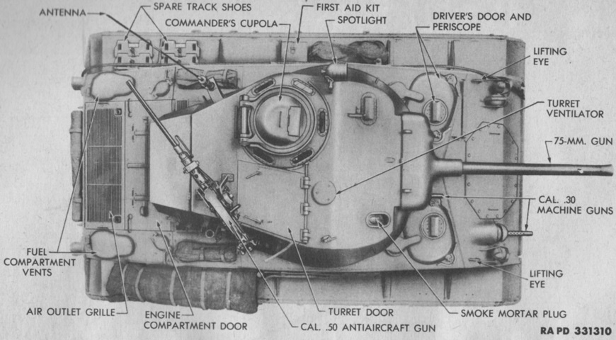
The top of the tank is seen in this picture; this earlier production machine is equipped with a spotlight in front of the commander's cupola as well as the smoke mortar in the turret roof's right front corner. The aperture for the smoke mortar would be plated over with its elimination after World War II. (Picture from TM 9-729 Light Tank T24 (M24).)
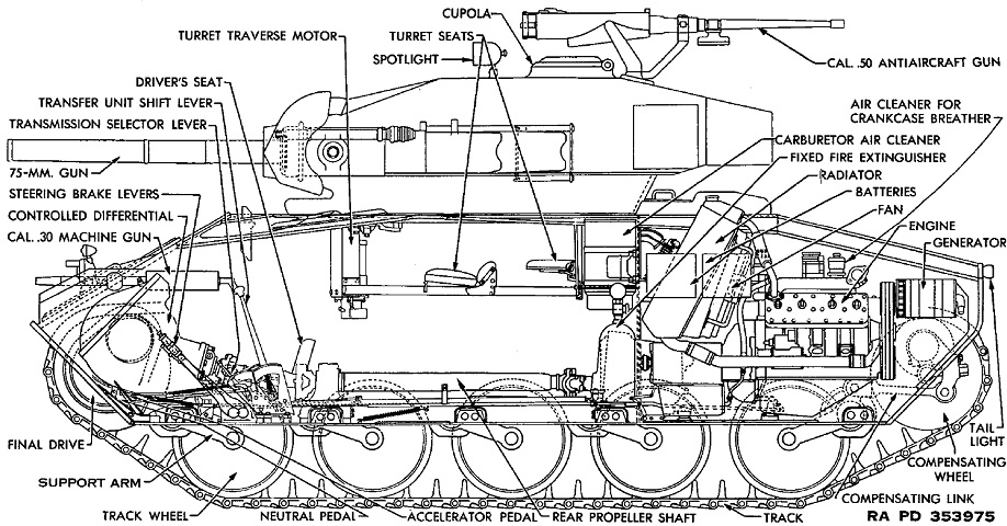
The innards of the tank are diagrammed in this sketch. (Picture from TM 9-1729C Ordnance Maintenance--Light Tank M24 and 155-mm Howitzer Motor Carriage M41 Tracks, Suspension, Hull and Turret.)
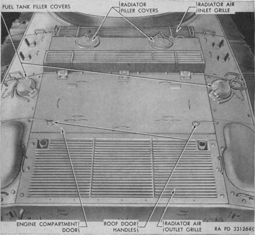
The engine compartment doors and covers are labeled in this image. (Picture from TM 9-729 Light Tank M24.)
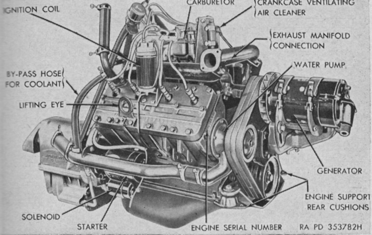
Each L-head engine displaced 346in³ (5.67L), with bore and stroke of 3.5" and 4.5" (8.9cm and 11.5cm), respectively. The compression ratio was 7.06:1, and each engine weighed 1,045lb (474.0kg) with accessories. (Picture from TM 9-729 Light Tank M24.)
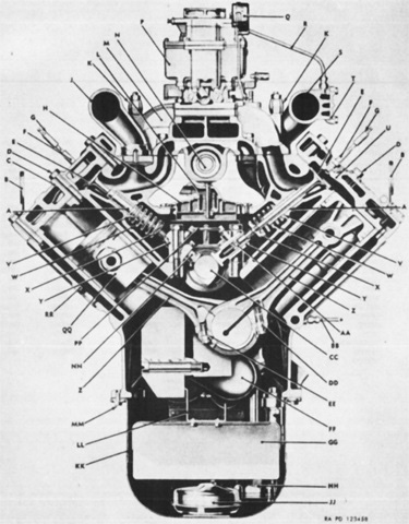
A transverse cross-section of an engine is drawn here. A. Guide. B. Eye. C. Head. D. Screw. E. Valve. F. Plug. G. Suppressor. H. Cover, assy. J. Manifold. K. Clamp. L. Line. M. Manifold. N. Shaft. P. Carburetor, assy. Q. Coil, assy. R. Line, assy. S. Manifold. T. Cover. U. Head. V. Seat. W. Spring. X. Seat. Y. Guide, assy. Z. Rod, assy. AA. Plunger, assy. BB. Line, assy. CC. Camshaft. DD. Screw. EE. Screw. FF. Crankshaft, assy. GG. Baffle, assy. HH. Pump, assy. JJ. Strainer, assy. KK. Pan. LL. Support. MM. Screw. NN. Tappet. PP. Line, assy. QQ. Piston, assy. RR. Block, assy. (Picture from ORD 9 SNL G-200 List of all Service Parts of Tank, Light, M24.)
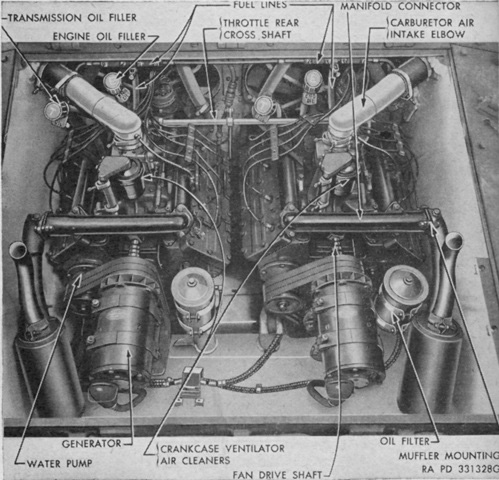
The two engines are shown here installed. (Picture from TM 9-729 Light Tank M24.)
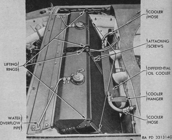
Each engine and transmission had its own separate cooling system, and the two Harrison engine radiators, each with a core area of 540.5in² (3,487cm²) are shown here. Each engine cooling system held 40 quarts (38L) of coolant. (Picture from TM 9-729 Light Tank M24.)
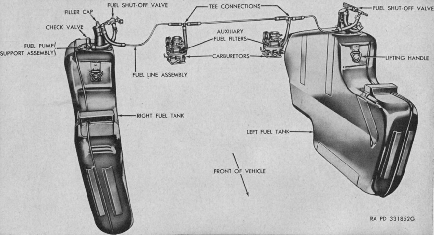
Two fuel tanks were ensconced in their own compartments on each side of the engine compartment. Either tank could supply fuel to both engines. (Picture from TM 9-729 Light Tank M24.)
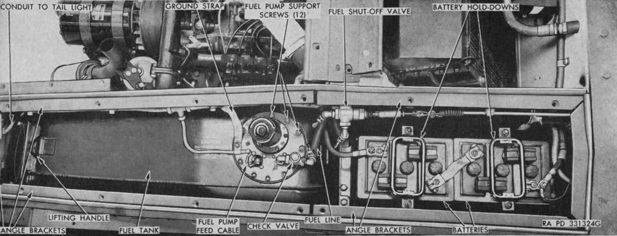
The right-hand fuel tank is installed in this image, and the location of the right-side battery box can also be seen. An identical battery box was located on the opposite side of the tank, and each box contained two 6-volt, 118-ampere-hour, 3-cell units connected in series, making a 24-volt electrical system. (Picture from TM 9-729 Light Tank M24.)
The clutchless hydramatic transmissions consisted of a fluid coupling and an automatic transmission with four forward speeds. The transmission itself had no reverse gear, this being provided instead by the transfer unit. Gear ratios for first through fourth speeds were, respectively, 3.92:1, 2.53:1, 1.55:1, and 1:1. (Picture from TM 9-729 Light Tank M24.)
The transfer unit, shown here being removed, was mounted between and ahead of the transmissions, and both combined the power output of the separate engines as well as provided its own two speeds forward and one in reverse. The transfer unit input gears were connected to the input shafts by sliding couplings, which allowed one engine to be disconnected if needed. Low gear ratio was 2.34:1, high was 1.03:1, and reverse was 2.44:1. The transfer unit used a manual synchromesh shift mechanism. (Picture from TM 9-729 Light Tank M24.)
The transfer unit is shown here installed. When the engine input clutch lever was in the rear position, the sliding clutch it controlled on the input gear was engaged with the input shaft. When the lever was moved forward, the clutch was disconnected. (Picture from TM 9-729 Light Tank T24 (M24).)
This ghosted view of the transfer unit reveals the transfer gears and clutches on the inside. (Picture from ORD 9 SNL G-200 List of all Service Parts of Tank, Light, M24.)
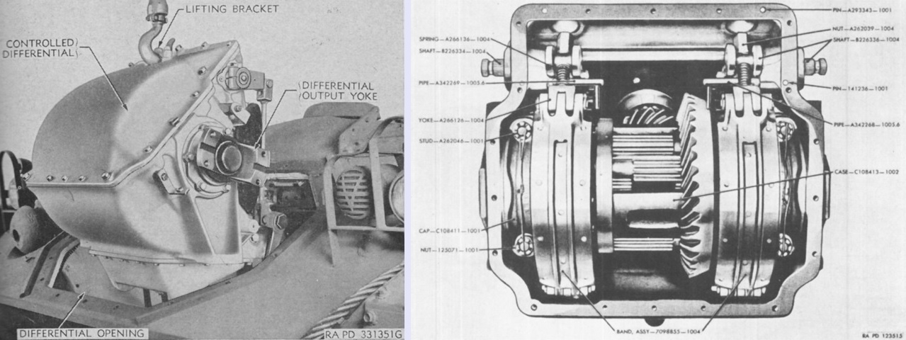
The controlled differential transmitted engine power to the final drives and contained the two brake assemblies that steered and stopped the tank. The differential cover was attached with 18 screws each torqued to 80-85 foot-pounds (108-115Nm). On the left, it is being removed from the vehicle; on the right, the controlled differential case is opened, revealing the differential gearing and steering brakes within. (Picture from TM 9-729 Light Tank M24 and ORD 9 SNL G-200 List of all Service Parts of Tank, Light, M24.)
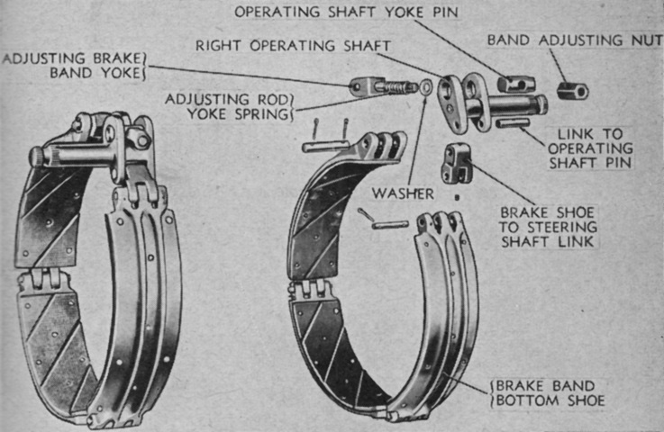
The brake rims were 15x4.25" (38x10.8cm), with the linings themselves being 13x4" (33x10cm). (Picture from TM 9-729 Light Tank M24.)
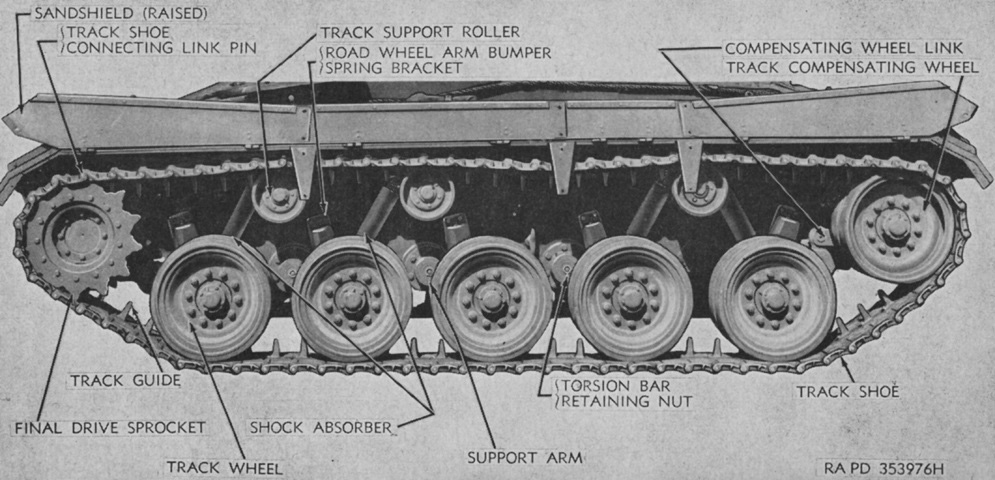
The sandshields have been raised, and the nomenclature for the suspension components is given. (Picture from TM 9-729 Light Tank M24.)
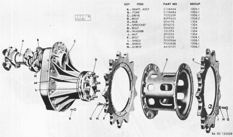
An exploded view of the final drive sprocket and hub is provided in this picture. (Picture from ORD 9 SNL G-200 List of all Service Parts of Tank, Light, M24.)
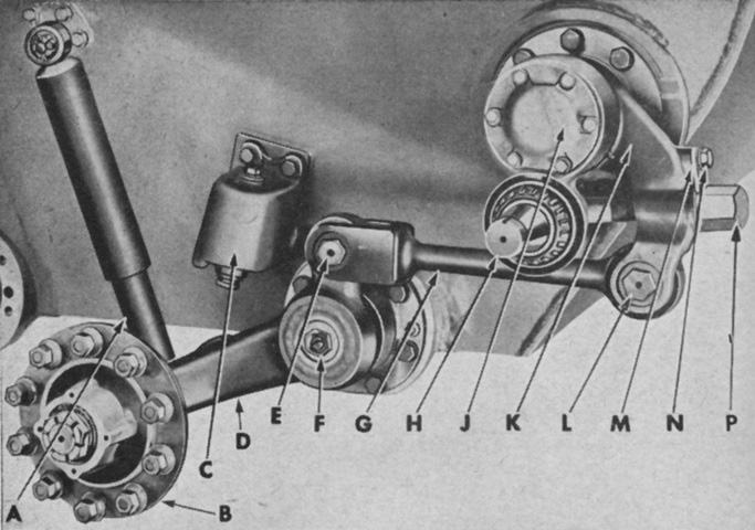
The compensating wheel and rear track wheel support arm and linkage are shown here with the wheels removed. The design connected the idler wheel with the rear road wheel so that any change in track tension imparted by the lifting of the rear road wheel was offset by the forward or rearward movement imparted to the idler wheel. Note that the rear road wheels were leading, while the rest of the road wheels were trailing. A. Shock absorber. B. Wheel hub. C. Arm bumper spring bracket. D. Support arm. E. Compensating wheel link bolt. F. Torsion bar retaining nut. G. Compensating wheel link. H. Compensating support arm spindle. J. Compensating wheel support arm cover. K. Inner support arm. L. Compensating wheel link bolt. M. Clamping bolt stop. N. Clamping bolt. P. Adjusting nut. (Picture from TM 9-729 Light Tank M24.)
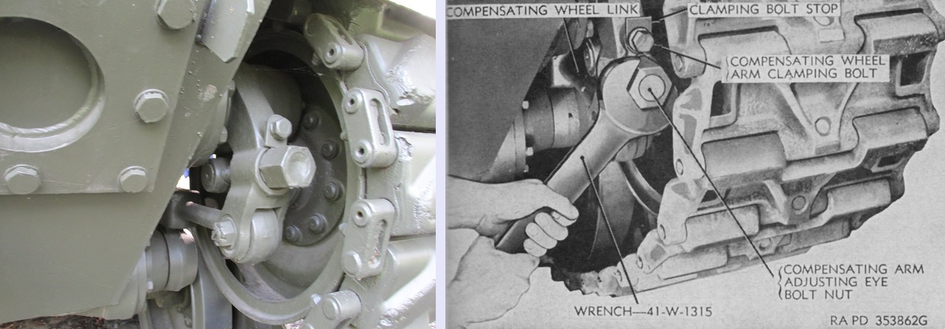
The compensating idler linkage is highlighted in these images. The idler wheels were connected to the rear road wheel arms so that the idlers could move to the front or rear if the rear road wheels moved down or up, respectively, thereby maintaining track tension and lessening the chance of the tracks being thrown. As seen on the right, track tension was adjusted by loosening the small clamping bolt so that the clamping bolt stop could be rotated out of the way, and then tightening or loosening the large track adjusting nut until track tension was correct. (Right picture from TM 9-729 Light Tank M24.)
A floor escape hatch was found behind the assistant driver's seat, between the second and third road wheels. Removable inspection plates were available under each engine and transmission. The ones on this tank may be display replacements, though, as they appear to lack the drain covers for the engines and transmissions.
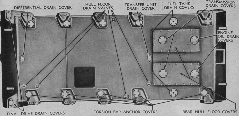
The engine and transmission inspection plates referenced above can be seen here, along with other drains and openings in the hull floor. (Picture from TM 9-729 Light Tank M24.)
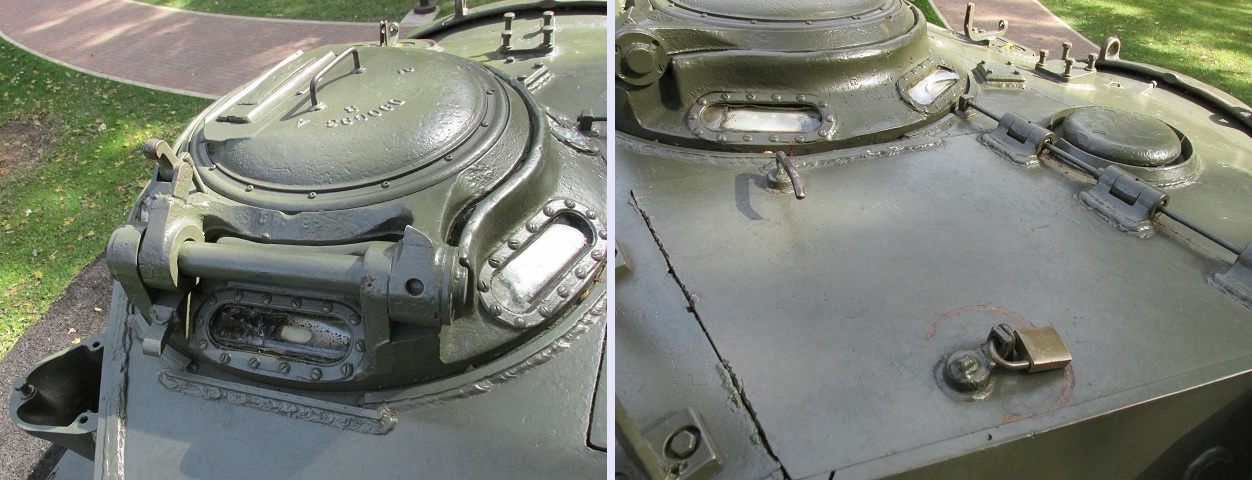
On the left, the commander's cupola is shown from the rear. The commander had six vision blocks ringing the bottom of the cupola as well as a periscope in the rotating cupola door. An antenna mount is visible on the turret side. On the right, the loader was provided with a forward-opening door in the turret roof that was assisted by a torsion bar spring. The turret ventilator is in front of the loader's door.
The aperture for the 2" smoke mortar is plated over in the foreground of the left image. In front of the commander's cupola can be seen a mount for a spotlight, the commander's vane sight, and the gunner's periscope opening. Spotlights were only installed on early production tanks, and once their use had been discontinued, tanks with lights already installed simply used them until they became inoperative or broken. On the right, the smoke mortar M3 is shown installed while it was still in use. It was fixed in the turret roof and relied on turret traverse for aiming. (Right picture from TM 9-729 Light Tank T24 (M24).)
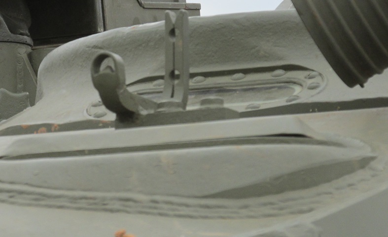
The commander's sighting vane visible in the image above is highlighted here. This allowed the commander to quickly slew the turret onto a target and decrease engagement times. The aperture for the gunner's periscope is in the hull roof in the foreground, and a spotlight is intruding into the image from the upper right.
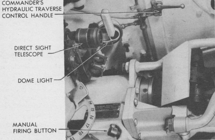
The commander was provided with a remote control handle on the turret roof that allowed him to traverse the turret if desired. The commander's handle automatically cut out the gunner's controls, so any input by the commander would override the gunner. (Picture from TM 9-729 Light Tank T24 (M24).)
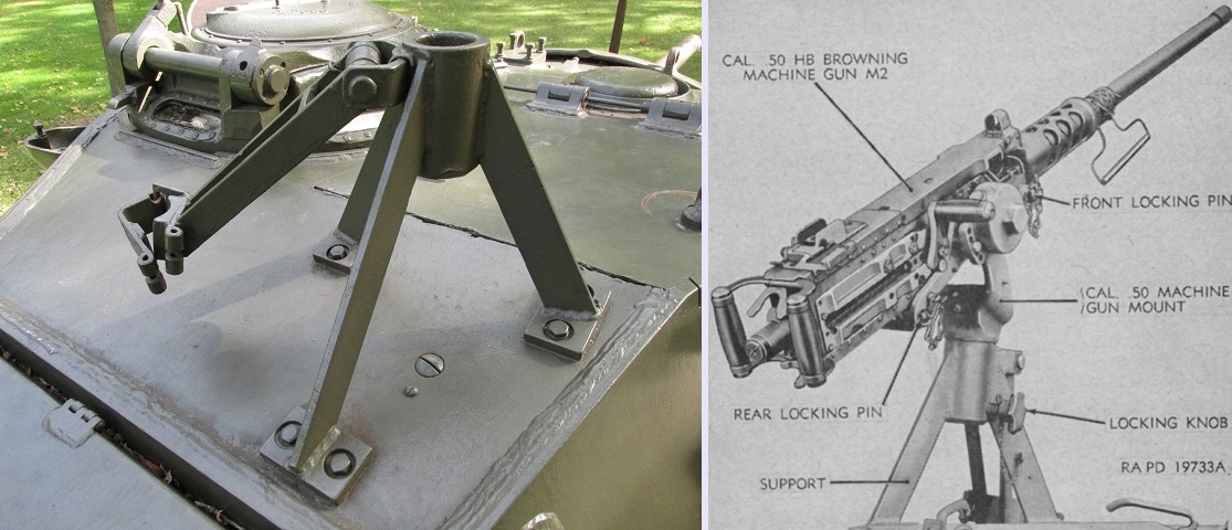
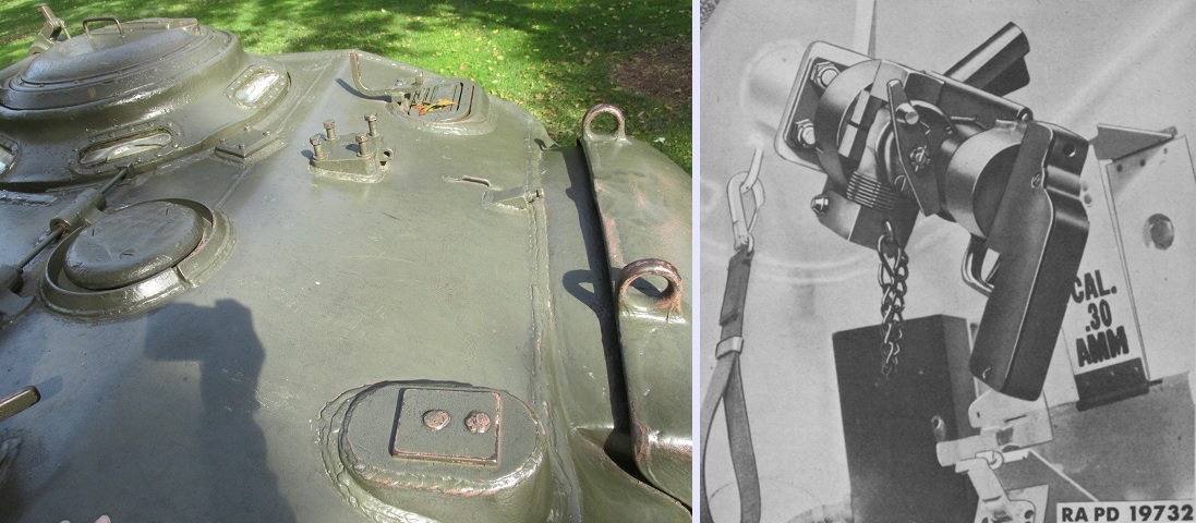
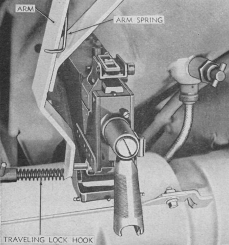
As seen on the left, the .50cal machine gun mount was a tripod affair bolted to the rear turret roof. The arm folded down to the left is the travel lock for the machine gun. On the right, the machine gun is mounted. (Right picture from TM 9-729 Light Tank M24.)
When not in use, the .50cal machine gun with its cradle and pintle were secured with a strap in a socket with on the turret side. The barrel was removed and held against the turret by clips. (Picture from Weapon Mounts for Secondary Armament.)
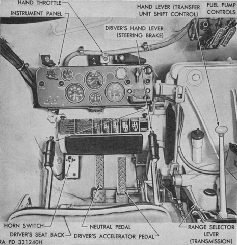
The driver's controls are detailed here. The driver and assistant driver each had a set of pedals and levers (although the assistant driver lacked knobs on the steering lever ends to activate the parking brakes). The transmission range selector lever allowed the driver to select neutral, drive, or low range. This lever did not shift gears, but positioned the valves in the transmission control mechanism for the appropriate range. Low range allowed shifting through first and second speeds to take advantage of engine braking. The transfer unit shift control lever had positions for neutral, high and low ranges, and reverse. The accelerator pedal controlled both engines, and the neutral pedal allowed the driver to temporarily throw the tank into neutral without moving the transmission range selector. Releasing the pedal returned the transmissions to the selected lever position. Even though the transmissions were automatic, switching the transfer unit shift control between ranges required them to be in neutral, and the neutral pedal allowed the driver to do this without shifting the transmission range selector into neutral. (Picture from TM 9-729 Light Tank M24.)
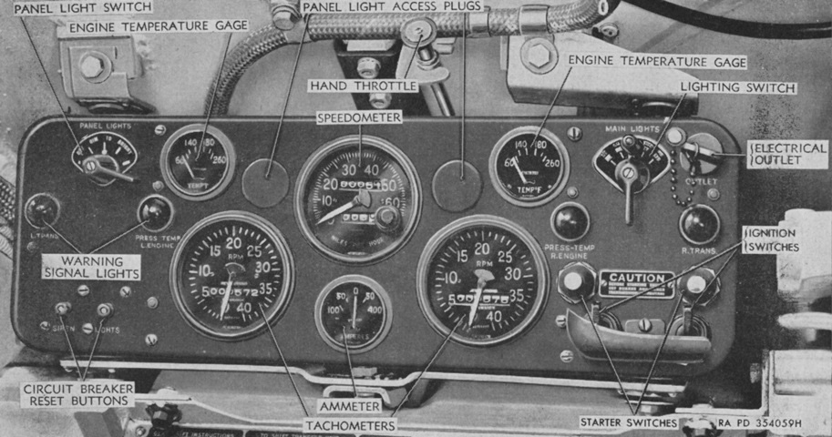
The driver's instrument panel is labeled here. (Picture from TM 9-729 Light Tank M24.)
The assistant driver's machine gun is illustrated in this picture. It had no sighting device; aiming was accomplished via tracers and impacts. The locking handle for the right headlight assembly can be seen to the right. (Picture from TM 9-729 Light Tank M24.)
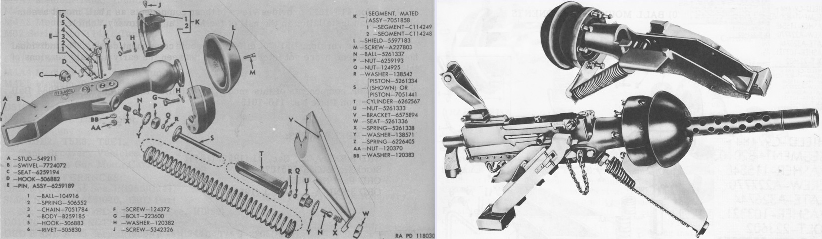
Exploded and assembled views of the caliber .30 ball mount 6576459 are shown on the left and right, respectively. Initially designated D76459, the mount featured an equilibrator spring, and an expended link chute and expended case collection bag were fastened to the mount. The gun was secured to the cradle by its front mounting holes, and its rear mounting holes were used for the quick-disconnect travel lock. Ammunition was stowed to the assistant driver's left, and fed to the gun via a flexible chute. (Picture from Weapon Mounts for Secondary Armament.)
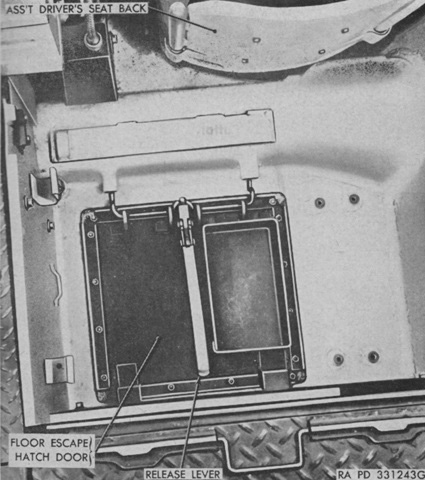
A floor escape door was positioned behind the assistant driver. The subfloor over the escape door needed to be removed in order to provide access, then the release lever could be raised, allowing both the door and the 75mm gun spare parts box on top of it to fall to the ground. (Picture from TM 9-729 Light Tank M24.)
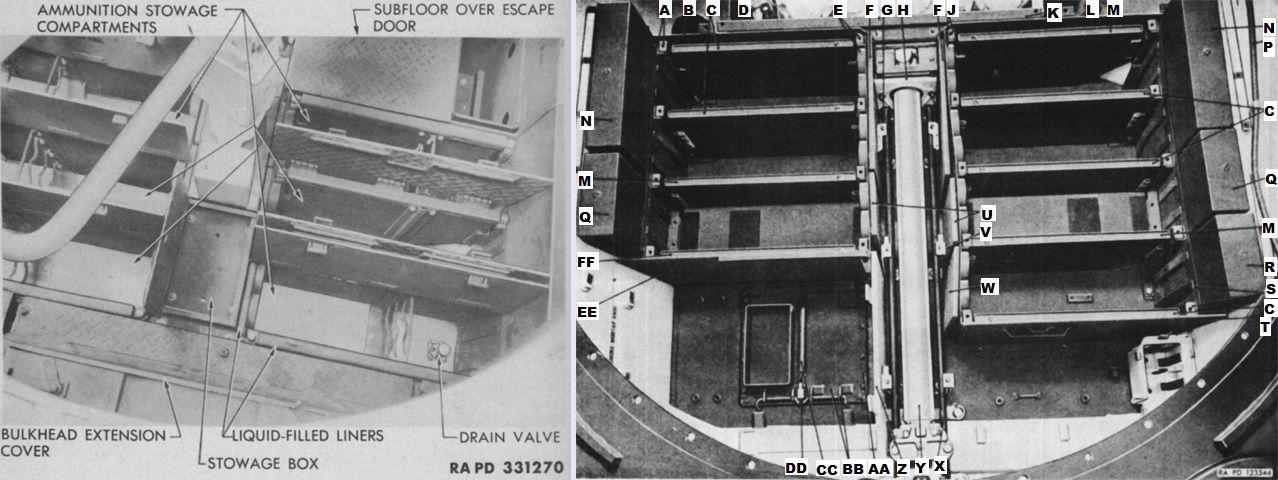
All main gun ammunition stowage was in underfloor boxes. The tank was originally designed with wet stowage, where the ammunition was protected by twenty-one liquid-filled containers of ten different sizes. The liners could be filled with water, a rust inhibitor, and antifreeze. By the early 1950s, though, this practice had been discontinued, and the fluid in the ammunition boxes was to be removed.
The right image shows the ammunition racks and cans with the floor panels removed. A. Panel, assy. B. Panel, assy. C. Can, assy. D. Valve, assy. E. Panel, assy. F. Can, assy. G. Support. H. Plate. J. Panel, assy. K. Cover, assy. L. Panel, assy. M. Can, assy. N. Can, assy. P. Harness, assy. Q. Can, assy. R. Can, assy. S. Panel, assy. T. Panel, assy. U. Can, assy. V. Support. W. Can, assy. X. Support, assy. Y. Shaft, assy. Z. Cover, assy. AA. Reinforcement. BB. Door, assy. CC. Lever. DD. Link. EE. Panel, assy. FF. Can, assy. (Picture from TM 9-729 Light Tank T24 (M24) and ORD 9 SNL G-200 List of all Service Parts of Tank, Light, M24.)
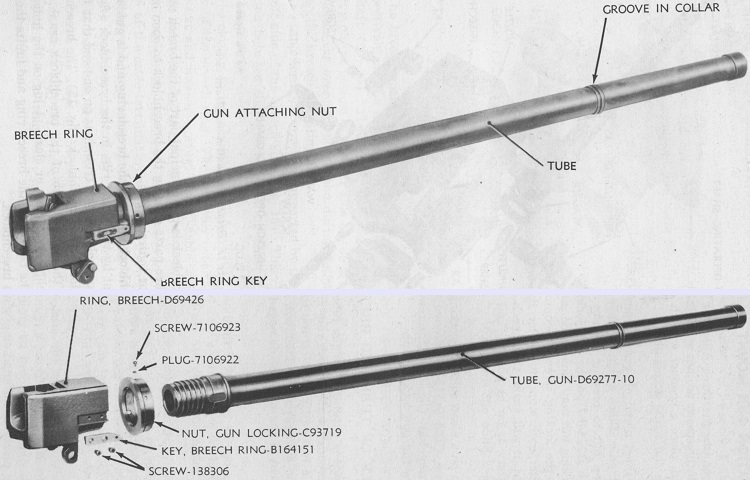
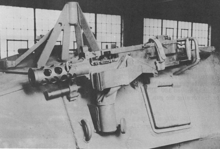
The 75mm gun M6 was a lightweight cannon with a semiautomatic horizontal sliding-wedge breech containing a continuous-pull, self-cocking type fire lock. Compared to the 75mm guns M2 and M3, the M6's tube had a more slender outside diameter, resulting in a weight of only 406lb (184kg). It was 116.375" (295.293cm) long, and its tube had a condemnation life of 1,000 rounds. Note the grooved collar in the gun tube toward the muzzle; this was a vestigial artifact from the gun's use in the B-25H's recoil system and was eliminated on later guns meant for tanks. (Picture from TM 9-313 75-mm Gun M6 and Combination Gun Mount M64 and TM 9-1313 Ordnance Maintenance--75-mm Gun M6 and Combination Gun Mount M64 (Tank).)
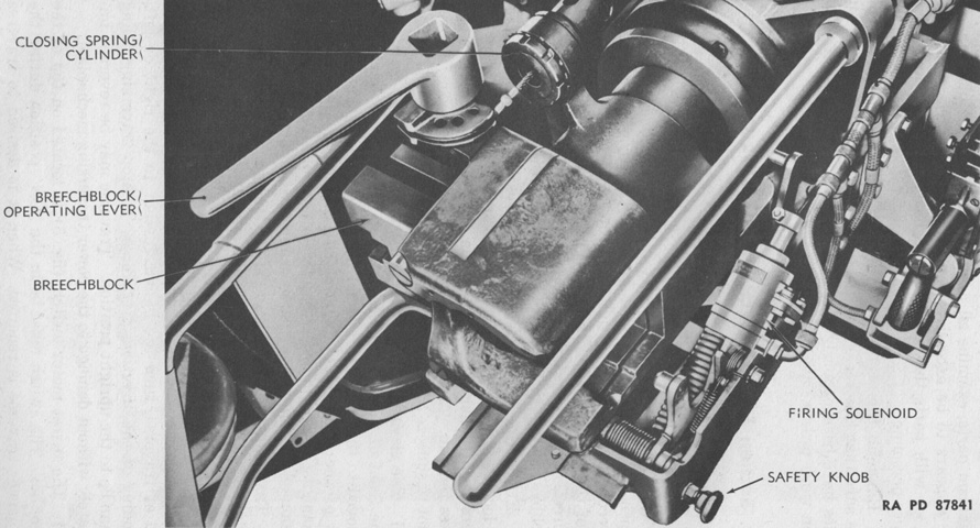
The breechblock is open in this image, being slid to the left. The breechblock operating lever was normally stowed in a bracket on the rear of the recoil guard and was retrieved when the breechblock needed to be opened manually. (Picture from TM 9-313 75-mm Gun M6 and Combination Gun Mount M64.)
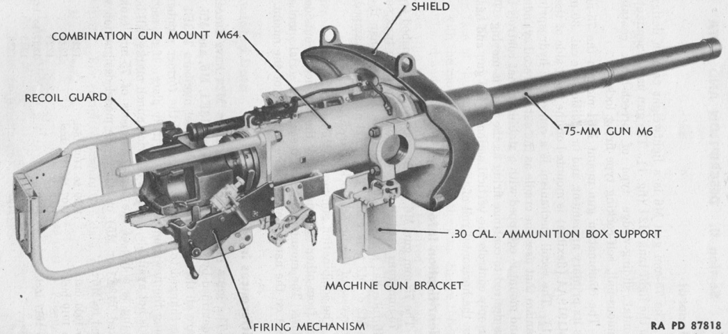
The 75mm gun M6 is shown assembled in the combination gun mount M64, but the coaxial machine gun is not mounted. Note the mount's lack of external recoil cylinders. (Picture from TM 9-313 75-mm Gun M6 and Combination Gun Mount M64.)
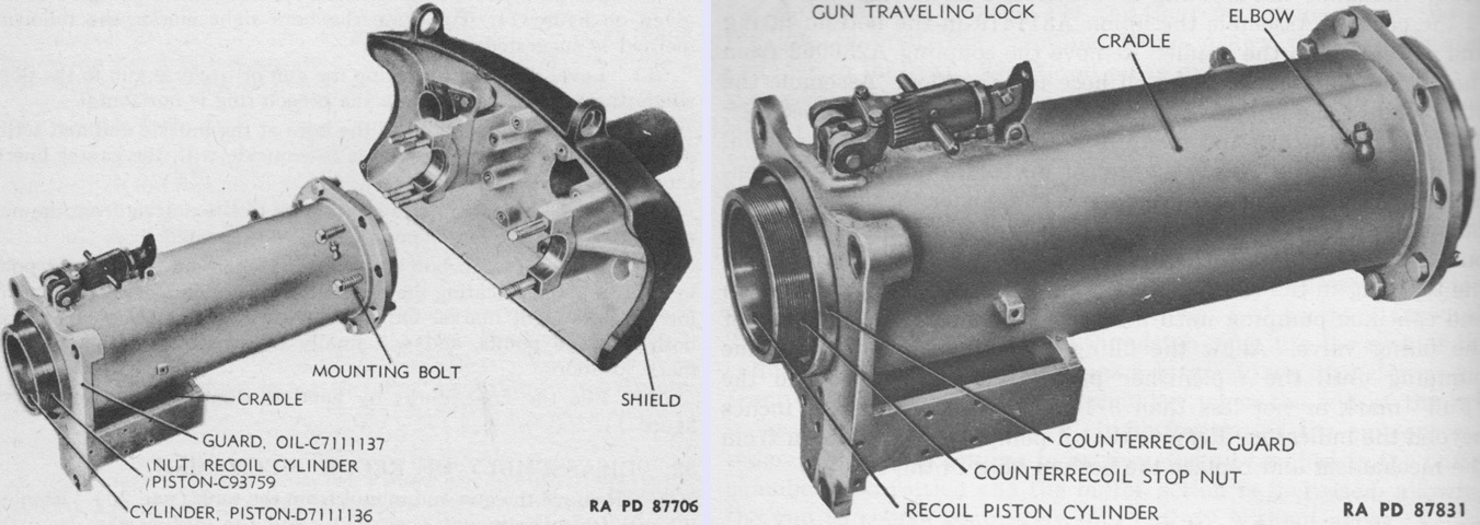
The gun cradle and shield are separated on the left, and the cradle is isolated on the right. The combination gun mount weighed 1,174lb (532.5kg). The right trunnion cap bolted to the gun shield and helped secure it to the turret, while the traversing rack formed the left trunnion cap. The cradle was mounted to the shield using eight bosses formed on the shield's interior. The internal gun travel lock can be seen atop the cradle. (Picture from TM 9-313 75-mm Gun M6 and Combination Gun Mount M64 and TM 9-1313 Ordnance Maintenance--75-mm Gun M6 and Combination Gun Mount M64 (Tank).)
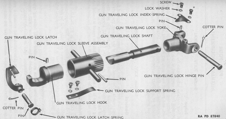
The gun travel lock is exploded in this image. When needed, it was swung up to engage a bracket on the turret ceiling. (Picture from TM 9-313 75-mm Gun M6 and Combination Gun Mount M64.)
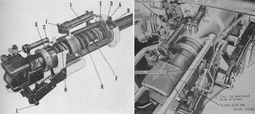
The concentric hydrospring recoil mechanism M22 of the combination gun mount M64 is the subject of the cutaway on the left. The 75mm gun is out of battery in this image. The recoil mechanism was built around the gun tube, and consisted of three cylinders and a spring. The outer cylinder was the gun cradle, and remained stationary. The interior wall of the cradle had six throttling grooves running lengthwise that gradually decreased in depth from front to rear. The inner cylinder was the recoil support cylinder, which provided support for the recoil piston cylinder and acted as a bearing surface for the gun tube recoil movement. The center cylinder was the recoil piston cylinder, and was secured to the gun tube by the gun attaching nut. The space between the cradle and the recoil support cylinder was completely filled with recoil oil. A. Gun cradle. B. Piston support cylinder. C. Recoil piston cylinder. D. Recoil piston ring. E. Counterrecoil spring seat. F. Counterrecoil spring. G. Gun attaching nut. H. Counterrecoil spring ring. I. Replenisher cylinder. J. Replenisher filling valve. K. Gun tube. L. Safety knob.
The combination gun mount M64 is shown installed on the right. The normal recoil stroke was 11.5" (29.2cm), with a maximum of 12.5" (31.8cm). The recoil mechanism held around 9 quarts (8.5L) of oil. (Picture from FM 17-12 Tank Gunnery and TM 9-729 Light Tank M24.)
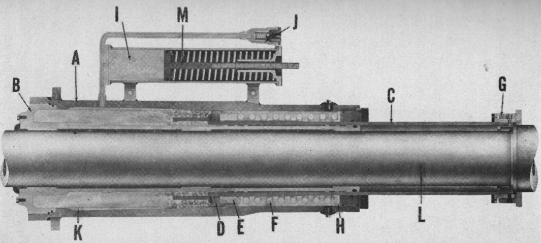
The recoil mechanism is again diagrammed with the gun out of battery. The recoil piston cylinder moved to the rear with the gun tube during recoil, forcing oil around the back side of the piston through the throttling grooves in the gun cradle. Hydraulic resistance gradually increased as the piston moved rearward due to the decreasing depth of the throttling grooves. This resistance, combined with the increasing resistance of the compression of the counterrecoil spring, arrested rearward movement of the gun. The counterrecoil spring then expanded, bringing the gun back into battery. A buffer chamber was formed by the flange on the front of the recoil piston cylinder riding over the shoulder of the piston support cylinder, and oil forced out of this chamber cushioned the last portion of the counterrecoil stroke, guarding against shock as the gun returned to battery. The replenisher acted as an oil reservoir for the system. A. Gun cradle. B. Piston support cylinder. C. Recoil piston cylinder. D. Recoil piston ring. E. Counterrecoil spring seat. F. Counterrecoil spring. G. Gun attaching nut. H. Counterrecoil spring ring. I. Replenisher cylinder. J. Replenisher filling valve. K. Throttling groove. L. Gun tube. M. Replenisher piston. (Picture from FM 17-12 Tank Gunnery.)
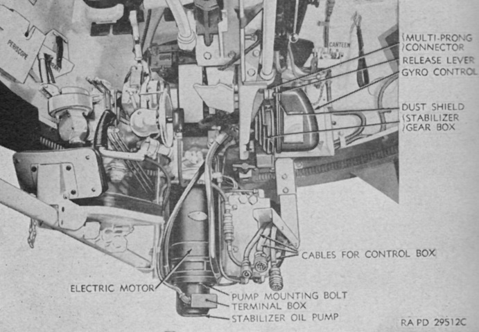
Components of the stabilizer system can be seen on the underside of the 75mm gun. (Picture from TM 9-729 Light Tank M24.)
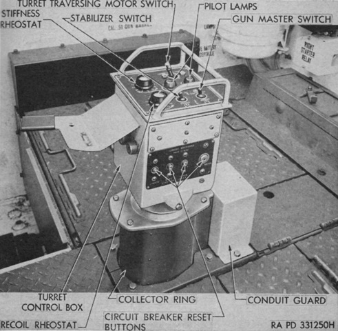
The electrical control switches for the turret are labeled in this image. The gunner was provided with rheostats to adjust the stiffness of the stabilizer's vertical resistance as well as resistance during recoil. Both of these could be adjusted on the fly as conditions dictated. (Picture from TM 9-729 Light Tank M24.)
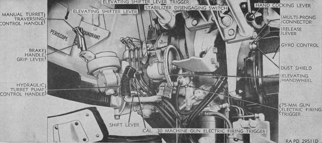
This turret interior view showcases the gunner's controls. To activate the gun's vertical stabilizer, the gunner would move the elevating shifter lever to the right. That lever removed the elevating arc and pinion gear from mesh and activated the disengaged switch contacts. Power or manual traverse was selected, respectively, by moving the shift lever up or down to disengage or engage the manual gearing. When using power traverse, the hydraulic turret pump control handle was rotated clockwise or counterclockwise for right or left turret rotation, respectively. (Picture from TM 9-729 Light Tank M24.)
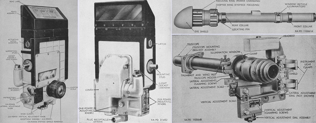
The periscope M16 is shown from the rear on the left, and the front of the periscope M10P is seen in the center image. Both periscopes had a 1x magnification window with a 42°10' horizontal and 8°10' vertical field of view with a reticle pattern for observation as well as a 6x telescope with a 10°20' field of view with a reticle pattern for distant targets. The periscope M4A1 with 1.44x telescope M38A1, M38A2, or M77G could also be installed in the gunner's periscope mount M66 with an adapter.
On the right, the telescope M83F is seen dismounted at the top, and the telescope M71K is installed in the telescope mount M65 at the bottom. The M71K used 5x magnification with a 13° field of view, while the M83F could use 4x or 8x magnification, with a 7°40' field of view at the lower power and a 4°15' field of view at the higher magnification. (Picture from TM 9-729 Light Tank M24.)
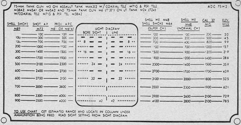
This firing table illustrates the reticle used by the telescope M38A2 in the periscope M4A1 and by the telescope M71G. (Picture from TM 9-729 Light Tank M24.)
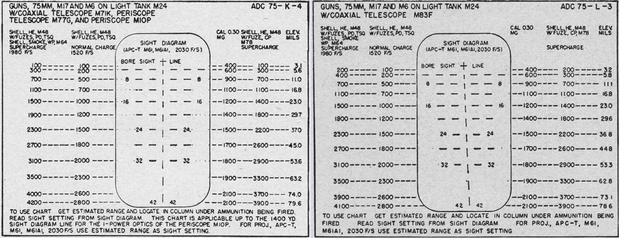
The firing table on the left shows the reticle found in the periscope M10P and telescopes M71K and M77G, while the one on the right details the telescope M83F. (Picture from TM 9-729 Light Tank M24.)
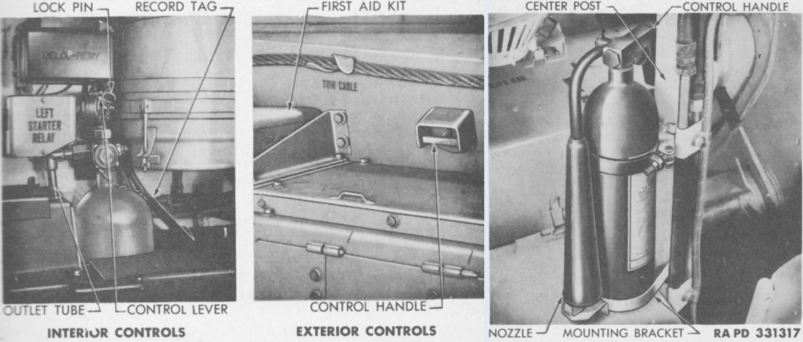
The fixed 10lb (4.5kg) CO2 fire extinguisher shown on the left was mounted on the left side of the bulkhead in the fighting compartment, and was used for fires in the engine compartment. Activation controls were placed in the fighting compartment and on the exterior of the hull just ahead of the engine compartment (center). In addition, a 4lb (2kg) portable CO2 fire extinguisher was carried on the post between the drivers (right). (Picture from TM 9-729 Light Tank T24 (M24).)
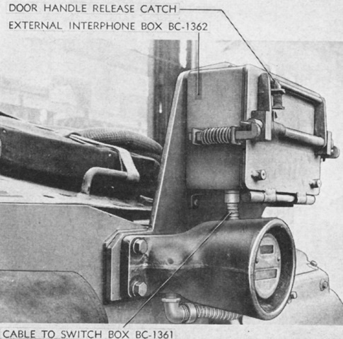
The interphone extension kit RC-298 allowed dismounts to communicate with the tank crew via the external interphone box BC-1362. This connected to the switch box BC-1361 mounted at the rear of the assistant driver's position, and was itself connected to the vehicle interphone by tapping into the terminal box to the assistant driver's left. (Picture from TM 9-729 Light Tank M24.)
