106mm Multiple Self-propelled Rifle M50.
Ontos, Greek for "that which is indeed" but commonly more loosely translated as "thing," is an apt nickname for this little vehicle. A .50cal spotting rifle can be seen on 106mm rifle number 2, but spotting rifles were not mounted on the bottom two 106mm rifles. (Picture from MICO P1550.228 The Ontos.)
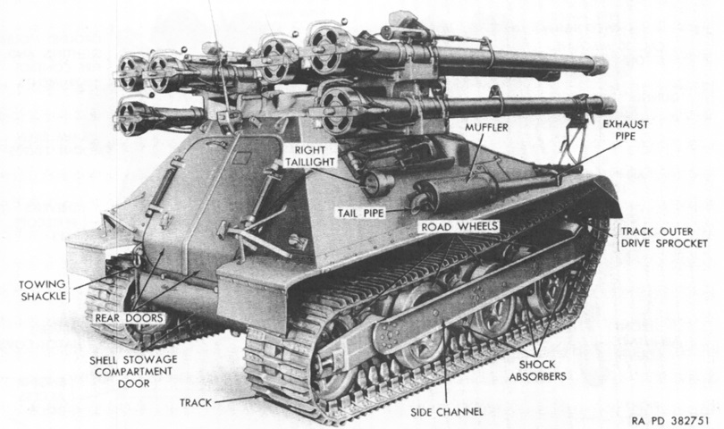
The right rear of the machine is shown here. The rear road wheel also acted as the trailing idler, and did not have a shock absorber attached. (Picture from TM 9-2350-212-12.)
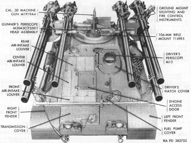
This illustration details the vehicle from above. Note the solid engine access door, which would be replaced by a louvred version on the M50A1. (Picture from TM 9-2350-212-12.)
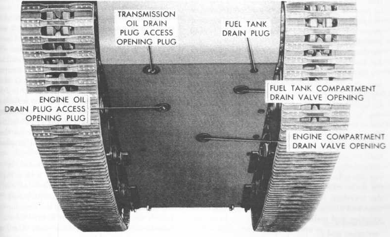
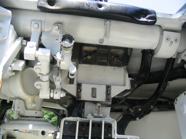
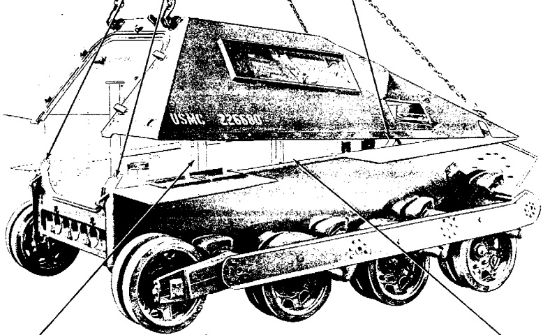
Openings on the hull underside are labeled in this picture. The front of the vehicle is nearest the camera. (Picture from TM 9-2350-212-12.)
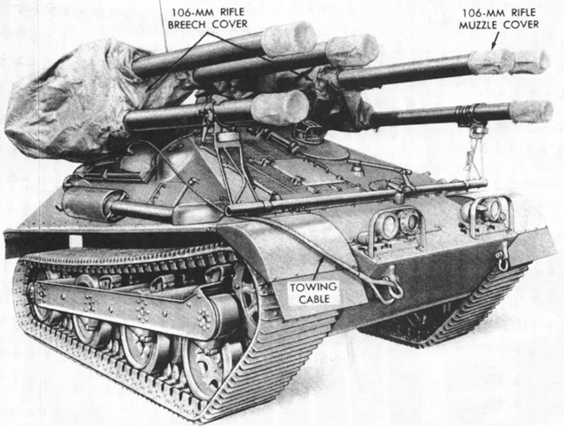
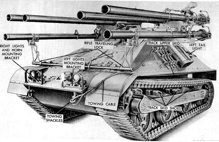
During transit, covers could be installed on the muzzles, and large covers protected the breeches of the rifles on each side. (Picture from TM 9-2350-212-12.)
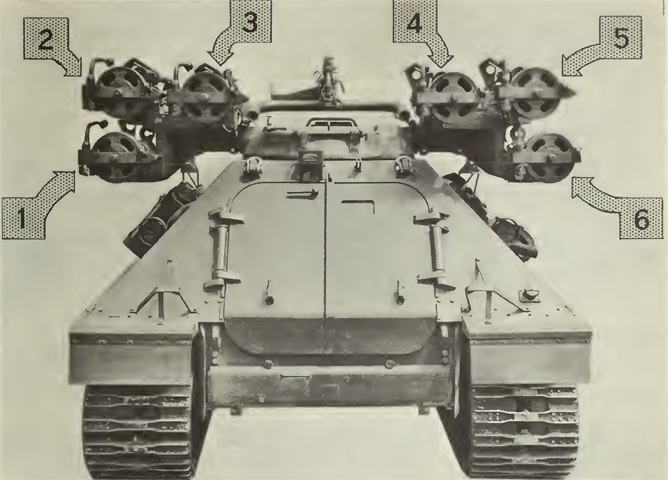
The numbering scheme of the rifles is labeled here. (Picture from FMFM 9-3 Antimechanized Operations.)
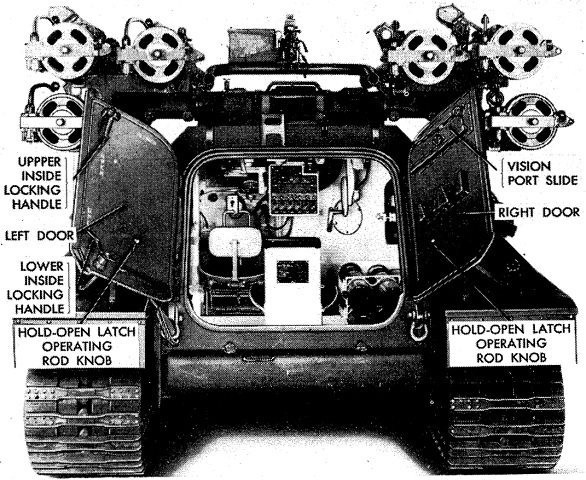
The rear doors are open in this image, allowing a view into the crew compartment. The gunner's backrest is placed centrally, and the driver's seat is forward and to the left. (Picture from MICO P1550.228 The Ontos.)
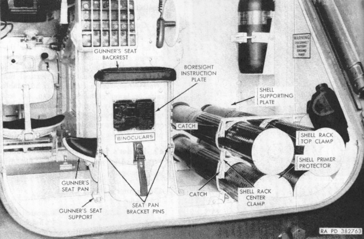
A closer view reveals stowage on the gunner's seatback and details of the four-round stowage rack to the gunner's right. A 5lb (2.3kg) capacity CO2 fire extinguisher was secured in a bracket on the right. (Picture from TM 9-2350-212-12.)
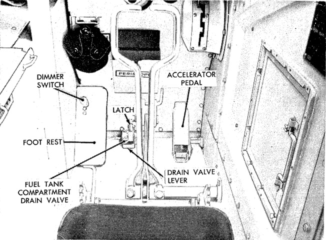
The driver's compartment is shown here. The steering brake control handles are directly in front of his seat. The labeled latch locked the drain valve in the open position; the steering brake control handles also had latches to lock them in position. (Picture from MICO P1550.228 The Ontos.)
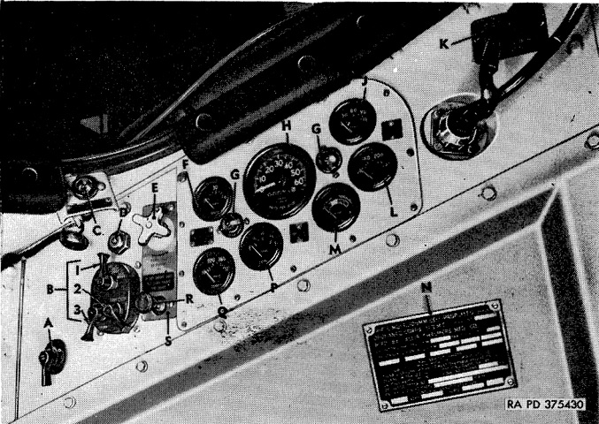
The driver's instrument panel is detailed in this photo. A. Ignition switch. B. Driving light control switch. 1. Main switch lever. 2. Switch locking lever. 3. Auxiliary switch lever. C. Transmission oil temperature and pressure warning light. D. Horn switch button. E. Fording shutoff valves control knob. F. Transmission oil pressure gage. G. Instrument panel light. H. Speedometer. J. Engine oil pressure gage. K. Battery cable caution plate. L. Engine temperature gage. M. Battery-generator indicator voltmeter. N. Vehicle identification plate. P. Fuel gage. Q. Transmission oil temperature gage. R. Choke control knob. S. Choke and fording control instruction plate. (Picture from MICO P1550.228 The Ontos.)
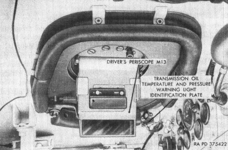
The driver's hatch is closed with his periscope in place. (Picture from TM 9-2350-212-12.)
The gunner's open turret hatch is shown here, with the machine gun mounted to his front. (Picture from MICO P1550.228 The Ontos.)
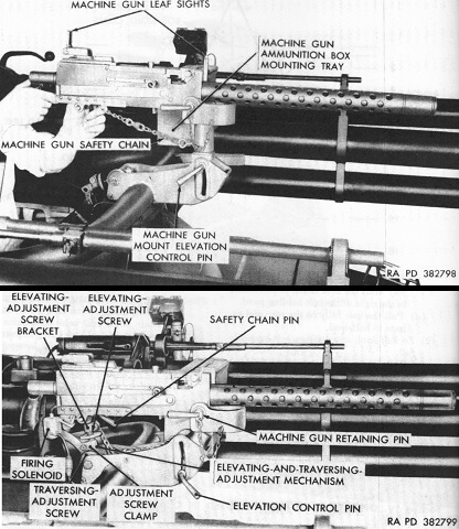
The machine gun could be aimed and fired manually (top) or it could be fixed so that it was traversed and elevated with the 106mm rifles (bottom). When locked down for remote use, the trigger was actuated by a solenoid activated by a foot trigger convenient to the gunner. (Picture from TM 9-2350-212-12.)
The gunner's sighting and fire control instruments are labeled in this image. At the upper left is a pump handle and below this a selector valve handle. The selector valve handle could be placed in either SAFE or CLOSE positions, and the pump handle was then used to open or close the rifle breeches. It took around eleven handle strokes to close the breeches and nine to open them. (Picture from TM 9-2350-212-12.)

The turret's left and right sides are is illustrated on the left and right, respectively. In the left image, the traversing handwheel and rifle breech actuator pump visible. The traversing mechanism was a worm gear type that drove the turret through a bevel pinion and traversing gear segment. The traversing gear bracket was hinged to allow a small amount of flexibility to the gear mesh, and the handwheel handle was hinged as well as to provide the driver with more room to enter or leave his position. The elevating screw assembly shown in the right image was a helical ball and screw arrangement where the ball jack screw was attached to the turret cross shaft by the elevating lever assembly. The elevating handwheel connected to the system via the elevating screw drive extension assembly, which was a roller chain and sprocket drive. The rifles were prevented from moving when the elevating handwheel was released by a Nobak mechanism in the housing, and the handgrip had a firing switch button on the front for the spotting rifles and on the top for the 106mm rifles. (Picture from TM 9-2350-212-12.)
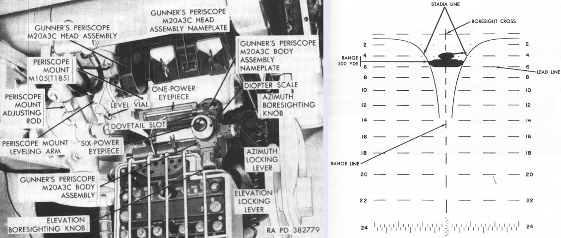
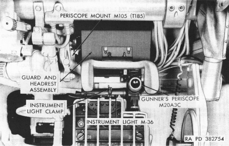
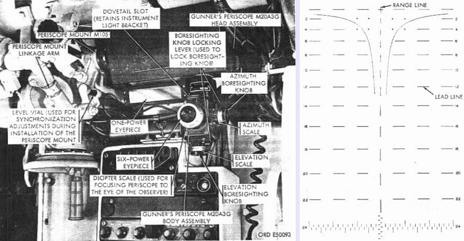
The gunner's periscope and mount are shown here with the guard and headrest assembly removed. The periscope mount M105 was attached to the turret roof and connected to the turret cross-shaft. This allowed the prism in the periscope head to rotate vertically as the cross-shaft elevated or depressed the rifles. The periscope's 6x reticle is sketched on the right, with a target tank being engaged. The boresight cross represented zero deflection and range, and each vertical range line and space represented 100 yards (91m). The horizontal lead lines and spaces were each 5 mils long. The stadia lines could be used for ranging, and were calibrated for targets 10' or 20' (3m or 6m) long. If a tank hull or other target that was ~20' (~6m) was broadside to the gunner, the periscope was adjusted until the front and rear ends of the target touched both stadia lines. If the target was ~10' (~3m) long (e.g., a tank facing directly toward or away), the target was lined up so that one end touched the center range line and the other end touched one of the stadia lines. The 5-10 mil lead lines were not drawn in the 200, 400, and 600 yard (180, 370, and 550m) range lines in order to avoid confusion with the stadia lines and to clean up the view through the reticle. These lead lines were replaced with dots whose centers represented the ends of where the lines would be drawn. The scale at the bottom of the reticle was normally used for indirect fire and was not utilized on this vehicle. (Picture from TM 9-2350-212-12.)
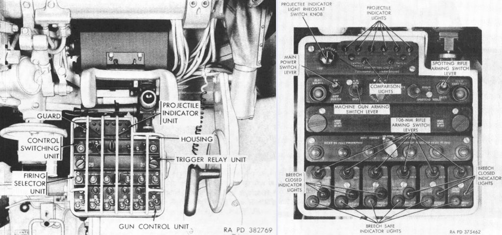
The weapons control panel was mounted below the gunner's periscope. The traverse handle is on the left and the elevation hand is on the right.
The weapons control panel is isolated in the right picture. The projectile indicator lights signaled which rifles were loaded: bright lights indicated an empty rifle while a dim light showed the rifle was loaded. The "E" and "L" comparison lights existed so that the brightness and dimness of the indicator lights could be ascertained. The row below the projectile indicator lights contained, from left to right, the 106mm rifle firing switch button; the main power switch lever; the machine gun arm/safe switch; a dimmer rheostat; spotting rifle selector lever; spotting rifle arming switch lever; and spotting rifle firing switch button. Spare lamps were stowed in the row below this. Under the spare lamps, next to fire indicator lamps showed the next rifle(s) that would discharge. The centrally-placed fire selector switch knob allowed the gunner to choose between manual, autosingle, or autodouble firing modes. Manual allowed the gunner to select the desired loaded and armed rifles to fire. All loaded rifles that were armed would fire with the trigger actuation. Autosingle fired one 106mm rifle, and each subsequent trigger actuation would fire the next in line. If all rifles were loaded and armed, they would fire in the order of 1, 6, 2, 5, 3, and 4. By pressing the desired next to fire indicator light, however, the gunner could choose the first rifle to fire. Autodouble would fire two armed rifles at a time; if all were loaded and armed, the sequence would normally fire rifles 1 and 6, then 2 and 5, and finally 3 and 4. However, as before, the gunner could choose which pair would begin by pressing the next to fire indicator light for the lower-numbered rifle of the pair. The bottom level contained the rifle arming switches and breech closed (red) and safe (green) indicator lights. (Picture from TM 9-2350-212-12.)
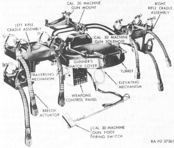
The 106mm rifle mount T149E5 is shown here from the rear. It included the armored turret, traversing and elevating mechanisms, and the weapons mount and control system. (Picture from TM 9-2350-212-12.)
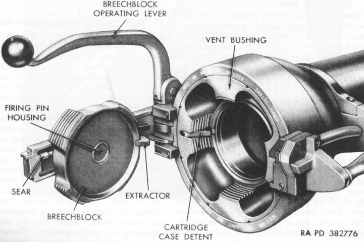
A 106mm rifle breech is open in this image. The operating lever was used to manually open and close the breech, and was forward when fully closed and 56° clockwise from the closed position when safed. (Picture from TM 9-2350-212-12.)
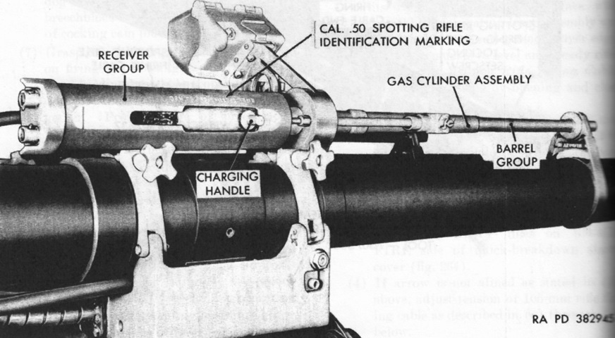
The M8C was a gas-operated, magazine-fed semiautomatic rifle. The guns mounted to 106mm rifles 3 and 4 were used with the vehicle, while those on rifles 2 and 5 were used when the recoilless rifles were set up in their ground mounts. Ammunition fired was closely matched to the trajectory of the 106mm rounds and utilized a tracer and a smoke puff on impact to help the gunner ascertain aim. (Picture from TM 9-2350-212-12.)

The M8C spotting rifles' magazines held twenty .50 caliber rounds. (Picture from TM 9-2350-212-12.)
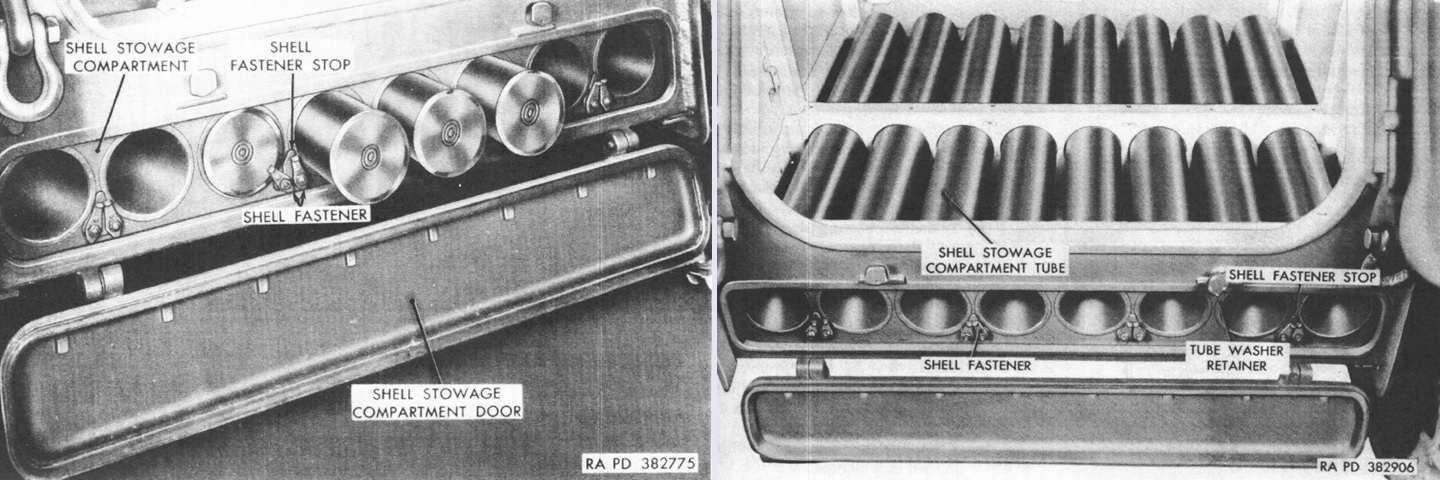
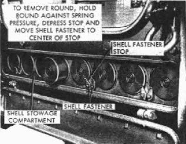
Eight 106mm rounds were stowed under the rear floor of the hull. The door was released via two latch handles under the hull's rear entry doors. The right image shows the rear shell stowage with the fighting compartment floor covers removed. (Picture from TM 9-2350-212-12.)
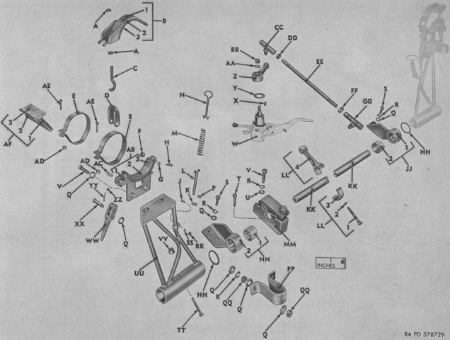
The rifle travel lock was a rather complicated affair. A. Nut. B. Clamp, assy. 1. Clamp. 2. Rivet. 3. Lining. C. Hook. D. Hoop. E. Strap. F. Spacer. G. Washer. H. Screw. J. Screw. K. Washer. L. Hanger. M. Spring. N. Handle. P. Spacer. Q. Washer. R. Washer. S. Screw. T. Screw. U. Washer. V. Screw. W. Ratchet, assy. X. Key. Y. Shim. Z. Arm. AA. Washer. BB. Nut. CC. Ball joint, assy. DD. Nut. EE. Rod. FF. Nut. GG. Ball joint, assy. HH. Spacer. JJ. Bracket, assy. 1. Bracket. 2. Bearing. KK. Shaft. LL. Lever, assy. 1. Screw. 2. Washer. 3. Cap. 4. Yoke. MM. Clamp, assy. NN. Bracket, assy. 1. Bearing. 2. Bracket. PP. Belt. QQ. Nut. RR. Nut. SS. Washer. TT. Screw. UU. Support, left; support, right. VV. Nut. WW. Handle. XX. Pin. YY. Pin. ZZ. Setscrew. AB. Saddle, assy. 1. Saddle. 2. Lining. 3. Rivet. AC. Pin. AD. Nut. AE. Screw. AF. Shoe, assy. 1. Shoe. 2. Rivet. 3. Lining. (Picture from ORD 9 SNL G-288.)
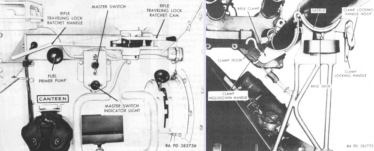
The rifle traveling lock was controlled from the driver's compartment via the ratchet cam and handle, seen in the left image. Once the clamp locking handles were released from outside, the driver could move the ratchet cam from its center neutral detent to its right lowering detent. The ratchet handle was then operated back and forth until the travel lock was fully lowered. To raise the lock from inside, the ratchet cam was placed into its left-hand raising detent, and the ratchet handle was then operated until the travel lock was raised. In combat conditions, the clamps were to be left open so that the travel lock could be released entirely from inside the vehicle; sufficient support was given when the rifles were firmly engaged by the travel lock and shoes with the travel lock locked into the raised position via the ratchet cam. As seen in the right image, the rifle traveling lock secured the lower rifle on each side. When opened, the rifle clamps were held under tension via the sprung clamp holddown handles. The rifles were engaged by the travel lock at the saddles as well as the rifle shoes. (Picture from TM 9-2350-212-12.)
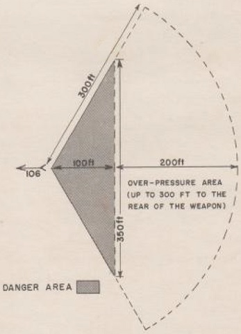
The backblast area of the 106mm rifle is diagrammed here. The danger area could contain flying particles and blast, and the overpressure area was powerful enough to damage windows or light structures. (Picture from LFB-23 Employment of the Antitank Battalion.)
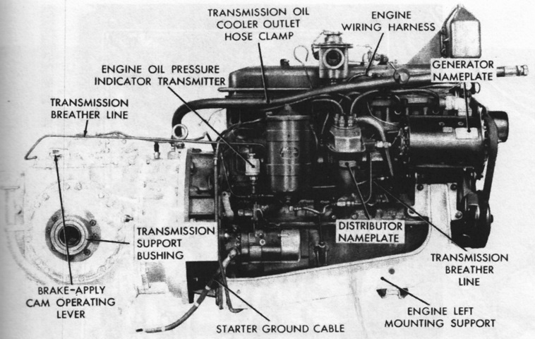
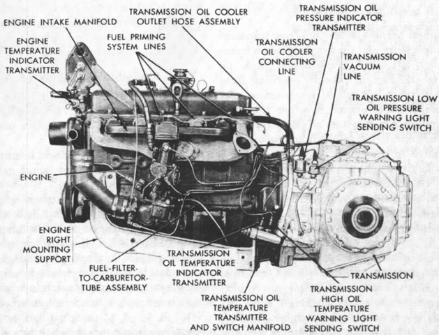
The powerplant's right side is shown in this picture. The fan end was considered the engine's front, and its right and left were determined by standing at the flywheel end (the rear) and looking toward the engine's front. The engine was a water-cooled valve-in-head type with a bore and stroke of 4" (10cm) apiece, for a displacement of 302in³ (4.95L). (Picture from TM 9-2350-212-12.)
The left side of the powerplant is labeled here. The engine was 38 17⁄64" (97.19cm) long overall, 24.75" (62.87cm) wide without the generator, and 32 23⁄32" (60.25cm) tall. (Picture from TM 9-2350-212-12.)
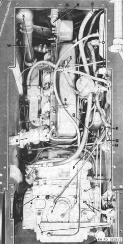
The powerplant is shown installed; the letters refer to disconnect points. The engine weighed 765lb (347kg) and had a compression ratio of 7.2:1. (Picture from TM 9-2350-212-12.)
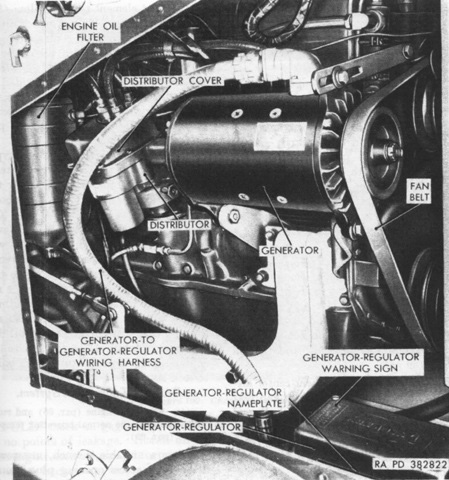
The engine's rear partition in the driver's compartment has been removed, illustrating components accessible from there. (Picture from TM 9-2350-212-12.)
The input end of the transmission, which was mounted pointing toward the rear of the vehicle, was considered the front. Slight pressure on the steering levers would disengage the appropriate drive clutch, while greater pressure would apply the brake on the desired side. Simultaneously pulling both levers all the way back would apply both brakes, but the steering valve would not disengage either drive clutch. (Picture from TM 9-2350-212-12.)
Shown here installed, the transmission was ~25.25 (~64.14cm) long, ~21.875" (~55.563cm) tall, and ~26.25" (~66.68cm) wide, and it weighed ~759lb (~344kg) dry. Gearing output ratios from the turbine to the drive sprocket (not counting the torque converter) were 27.0:1 for low range, 14.4:1 for intermediate, 6.4:1 for high, and 19.3:1 for reverse. The torque converter's maximum torque multiplication at stall was 3.8:1. (Picture from TM 9-2350-212-12.)
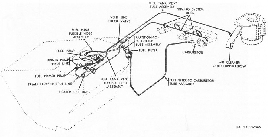
The fuel system is diagrammed here. The fuel tank was housed in a compartment in front of the driver to the left of the engine. (Picture from TM 9-2350-212-12.)
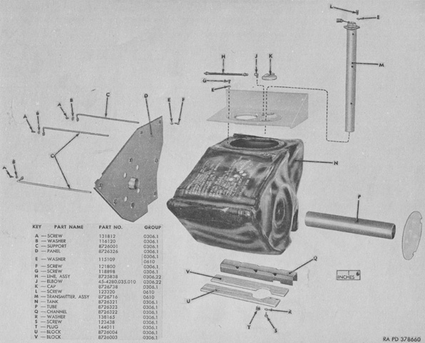
The fuel tank is isolated in this image. Manufactured by the Goodyear Tire and Rubber Company, it was of rubberized construction with three rubberized canvas hanger straps bonded to its top to provide support in the fuel compartment. A metal mounting flange around the top opening was bonded to the tank and featured tapped holes to secure the tank to the hull. The axle for the left final drive extended through the fuel tank to the transmission, and the crosswise opening for the axle is visible. The axle was surrounded by a fuel tank support tube. (Picture from ORD 9 SNL G-288.)
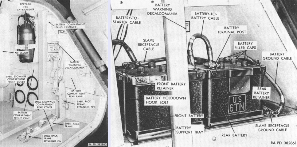
The battery compartment was found in the right rear corner of the hull. The shell supporting plate of the four-round ammunition rack is resting against the wall under the fire extinguisher. The compartment is opened in the right image. Two 12-volt batteries were connected in series to provide a 24-volt current. The batteries were submersible types that featured special vent plugs that prevented water from entering the cells. (Picture from TM 9-2350-212-12.)
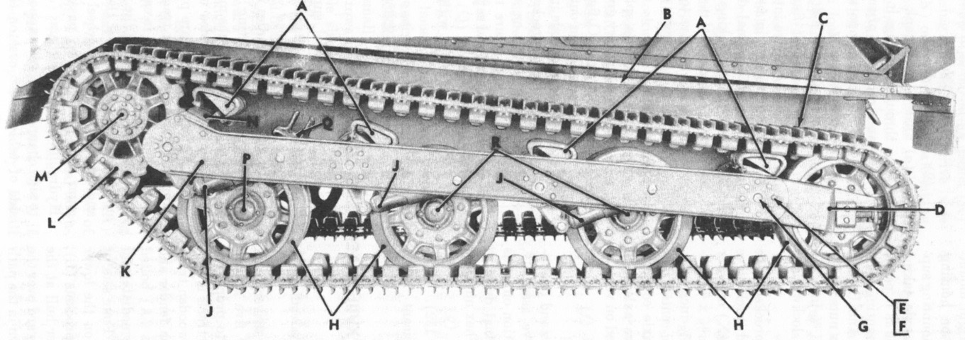
Suspension nomenclature is provided in this diagram. The track upper skids were wooden, and the track skid bumpers were covered in rubber. A. Track skid bumper. B. Track upper skid. C. Track assembly. D. Rear supporting arm. E. ½-inch [1.25cm] lockwasher. F. ½ x 1 [1.27cm x 2.54cm] hex-head capscrew. G. Side channel alinement hole plug. H. Road wheel. J. Shock absorber. K. Side channel. L. Track drive sprocket. M. Final drive. N. Front support. P. Front supporting arm. Q. Bumper spring assembly. R. Intermediate supporting arm. (Picture from TM 9-2350-212-12.)
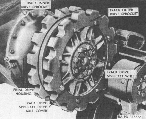
The drive sprocket can be seen with the track removed. (Picture from TM 9-2350-212-12.)
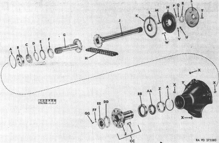
An exploded view of the left final drive assembly is provided here. The final drives each had an inner and outer axle that were connected by a double-width roller chain, providing a flexible drive between the two axles. The inner drive axle was splined to the transmission final drive planetary carrier, and the outer drive axle was splined to the sprocket drive axle. A. Bearing retaining snapring. B. 4.7812-inch [12.144cm] od bearing cup. C. 3.0625-inch [7.7788cm] bore bearing cone and rollers. D. 2.9530-inch [7.5006cm] id thrust washer. E. 2.9730 [7.5514cm] id, 4 3⁄16 [.476cm] od key washer. F. 2.9930-inch [7.5514cm] bearing nut. G. Outer drive axle. H. Roller chain. J. Inner drive axle. K. Pilot mounting gasket. L. 3.5433-inch [9.0000cm] od roller bearing. M. ½ x 1 ¾ [1.27cm x 1.91cm] stud. N. Inner drive axle pilot. P. ½-inch [1.27cm] lockwasher. Q. ½-inch [1.27cm] hex nut. R. 3.3550-inch [8.5217cm] od oil seal. S. Fuel tank support. T. ⅜ x 1 [.953cm x 2.54cm] hex-socket bolt. U. ⅜-inch [.953cm] hex nut. V. ⅜-inch [.953cm] lockwasher. W. ⅜ x 1 9⁄16 [.953cm x 3.969cm] stud. X. ½-inch [1.27cm] square-head pipe plug. Y. Housing. Z. 4.7812-inch [12.144cm] od bearing cup. AA. 3.0625-inch [7.7788cm] bore bearing cone and rollers. BB. 5.0040-inch [12.710cm] od oil seal. CC. Track drive sprocket axle assembly: 1. Pin. 2. Axle. DD. Track drive sprocket drive axle cover gasket. EE. Track drive sprocket axle cover. FF. ⅜-inch [.953cm] lockwasher. GG. ⅜ x ⅝ [.953cm x 1.59cm] hex-head capscrew. (Picture from TM 9-2350-212-12.)
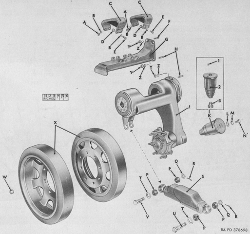
An exploded view of the front wheel installation is provided. Only the front wheels featured volute bumper springs. A. Screw. B. Washer. C. Shoe. D. Spacer. E. Screw. F. Stud. G. Support. H. Stud. J. Arm, left, assy; arm, right, assy. K. Spring, assy. 1. Pin. 2. Spring. 3. Tappet. L. Washer. M. Washer. N. Screw. P. Bushing. Q. Nut. R. Pin. S. Absorber, assy. T. Washer. U. Bolt. V. Bolt. W. Nut. X. Wheel. Y. Nut. Z. Washer. (Picture from ORD 9 SNL G-288.)
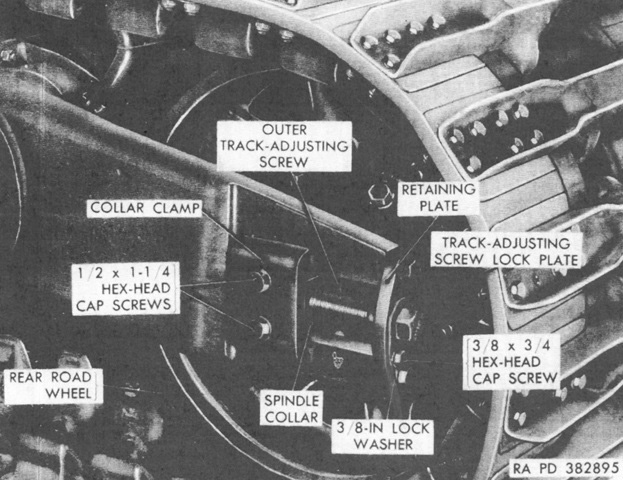
Track tension was adjusted by first loosening the two hex-head capscrews on the collar clamp and spindle plate, then removing hex-head capscrews securing the inner and outer track-adjusting screw lock plates to the retaining plates, which then allowed the lock plates to be removed. The inner and outer track-adjusting screws were then turned in the desired direction, with care taken to turn them the same amount to prevent the rear wheel's toe from becoming out of specification. (Picture from TM 9-2350-212-12.)
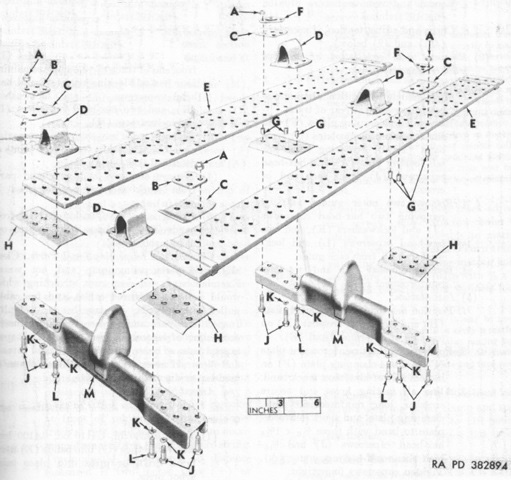
Components making up one of the five track sections are shown in this image. A. 5⁄16-inch [.794cm] hex self-locking nut. B. Track section joint plate. C. Short reinforcement plate. D. Outer guide. E. Band. F. Clamping plate. G. 0.3280 [0.8331cm] id, 0.4110 [1.044cm] od 0.4100 [1.041cm] sleeve bushing. H. Long reinforcement plate. J. 5⁄16 x 1 5⁄16 [.794cm x 3.33cm] hex-head capscrew. K. 5⁄16-inch [.794cm] lockwasher. L. 5⁄16 x 1 3⁄16 [.794cm x 3.02cm] hex-head capscrew. M. Crossbar. (Picture from TM 9-2350-212-12.)
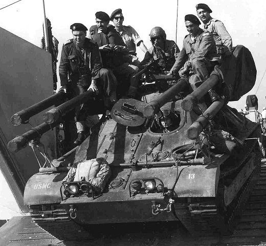
The driver and gunner of this vehicle can be seen at their stations, and the gunner's machine gun is uncovered in contrast to the recoilless rifles. The men riding on the rifles are members of the Lebanese Army. (Picture taken in 1958; available from the Marine Corps University.)
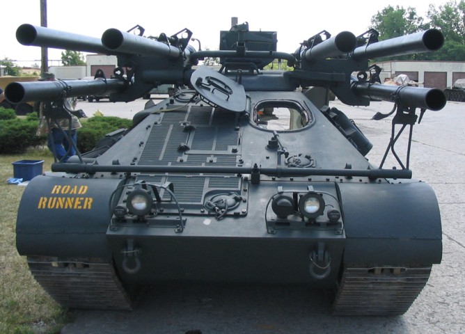
The rifle traveling lock is engaged in this imposing view of this beautifully restored machine. It is the bar running across the front of the hull that is attached to the bottom two rifles. The extra louvres on this vehicle are easily contrasted to the vehicles above. The gunner's periscope guard is visible between the rifles, and a machine gun mount is perched on the arm connecting the two groups of rifles.
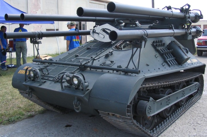
The beam running along the outside of the suspension was known as the side channel. Along with a spotting rifle, ground mount sighting and fire control instruments were stowed on the rear of the upper outer 106mm rifles. Stowage for a machine gun tripod is visible just in front of the spare track crossbars and outer guides.
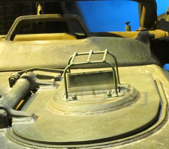
A closeup of the closed driver's hatch is provided here. His periscope is raised, and the gunner's periscope guard can be seen in the background.
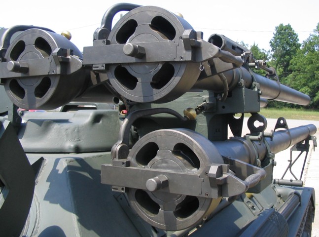
The breeches of the right three M40A1C rifles are visible here. The mount for the .50cal spotting rifle is apparent on the outboard recoilless rifle, and the vehicle's exhaust pipe and muffler can be seen running along the side of the hull.
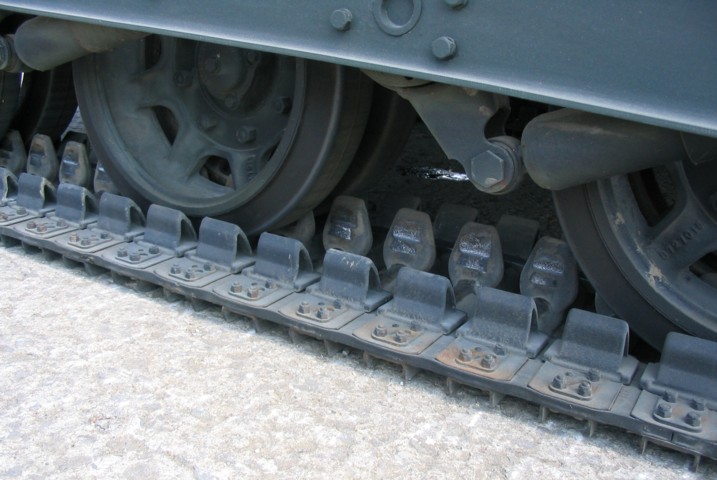
Details of the track and suspension can be seen here. The track has both center and outside guides, and each track is made up of five band-type sections. The rubber torsilastic springs are mounted externally, and have the benefit of being resistant to corrosion. Two of the vehicle's shock absorbers can be seen as well.
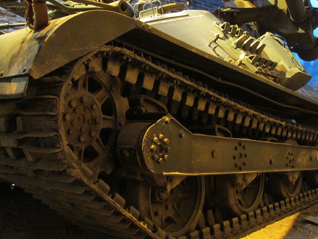
Another view of the drive sprocket and suspension is provided here.
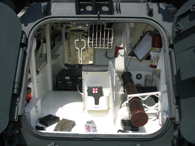
The rear double-door hatch is open on this vehicle. Stowage for four recoilless rifle rounds was provided in the rear of the fighting compartment. The first aid kit is mounted on the gunner's seat backrest, and his seat cushion can just be seen to the front of this. The gunner's control panel can be see to the front of the gunner behind a fence-like guard. The driver's position is at the front left of the hull, and the steering brake control levers are visible to his front since the backrest to his seat is not fitted.
A closer view of the gunner's controls and periscope mount is provided here.
The gunner's instruments and sights are mounted in this picture. The periscope M20A3G had a reticle pattern similar to the M20A3C, except that meters were used instead of yards. (Picture from TM-00545B-10.)
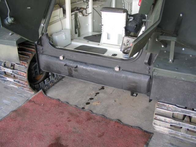
Stowage for eight 106mm rifle rounds was provided beneath the fighting compartment, and access was via this fold-down rear plate.
Another view of the the stowed ammunition is provided here. (Picture from TM-00545B-10.)
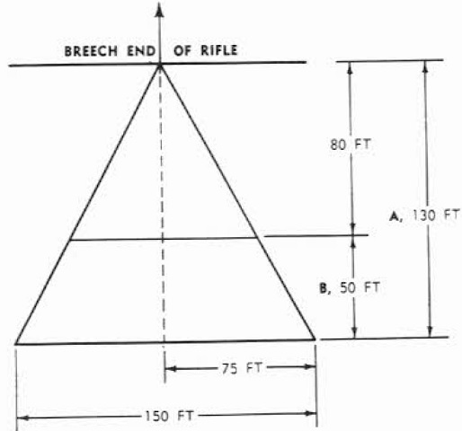
Another danger zone of a single 106mm rifle is detailed in this sketch. "A" represents the danger area due to blast and flying particles, while "B" was considered safe for personnel facing to the rear. The danger area for rifles fired in salvo or simultaneously was unknown. (Picture from TM-00545B-10.)
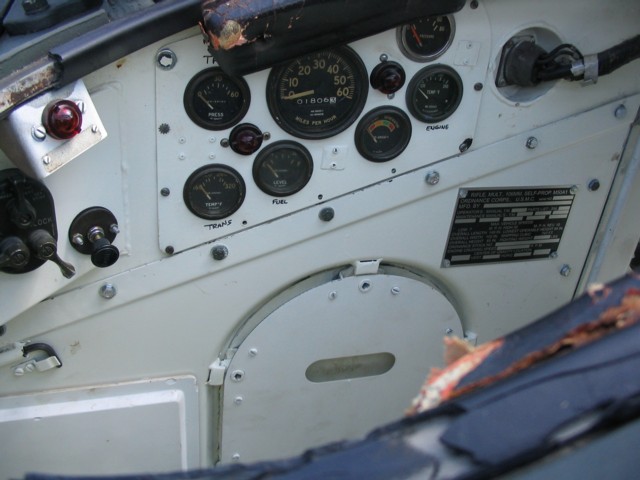
The driver's instruments are shown here. From left to right, the gauges are as follows: Transmission pressure (above), transmission temperature (below), fuel level, speedometer, battery generator, oil pressure (above), engine temperature (below). The three switches to the front of the image are for the vehicle's lights, and the engine choke knob is just behind the light switch group.
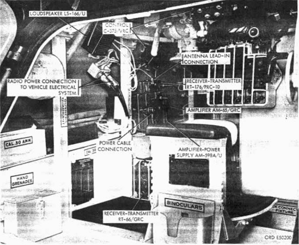
The location of the communication equipment is shown in this image. (Picture from TM-00545B-10.).
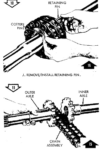
The final drive axles are shown joined by the roller chain and separated after the chain retaining pin has been removed. (Picture from TM-00545B-35/1.).
The vehicle's hull was made up from welded upper and lower hulls that were bolted together. The lower hull provided support for the suspension and final drives, while the upper hull mounted the 106mm rifles. The upper hull was mounted on six support posts that were welded onto the lower hull. (Picture from TM-00545B-35/1.).
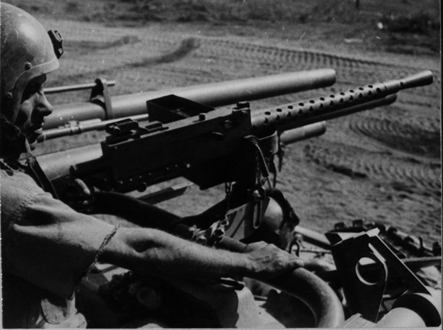
A more detailed view of the commander's machine gun mount is provided here, and the spotting rifles can be seen in the background. Vehicle commander Sgt Franklin Steed was providing cover for Marine Air Group 36 in Vietnam. (Picture taken 24 Jul 1966 by PFC Cowen; available from the National Archives.)
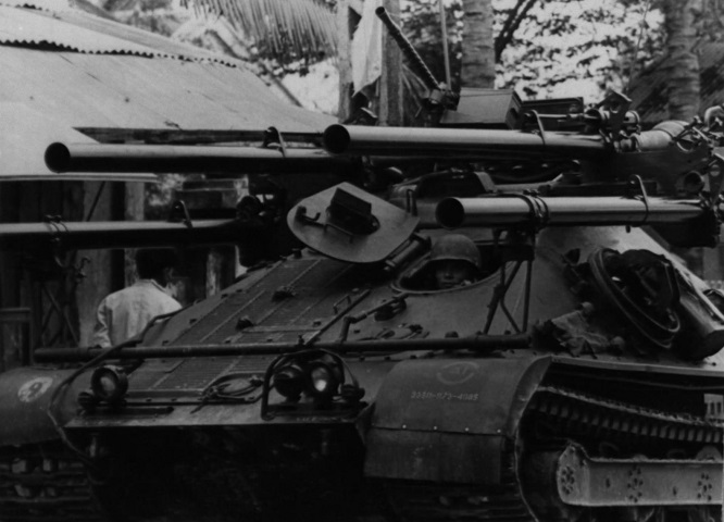
Note that this vehicle only has four recoilless rifles mounted. The rifles are in their travel lock, and the spotting rifles can be seen on the upper 106mm rifles. This crew was part of the III Marine Amphibious Force. (Picture taken 23 Feb 1968; available from the National Archives.)
