Armored Command Post Carrier M577.
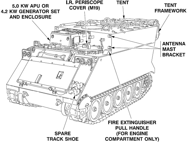
The raised passenger compartment is immediately apparent when the M577 is compared to the M113. The roof hatch can be seen just behind the generator set. Note the numerous antenna guards present on the roof. (Picture from TM 9-2300-224-10.)
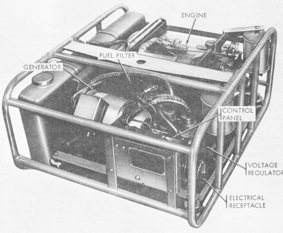
The air-cooled 28-volt, 4.2-kilowatt DC generator was equipped with a 6 gallon (23L) fuel tank. The generator was rated for 150 amperes at 3,600-3,700 governed rpm. The generator engine could be started via the vehicle's batteries or with a pull rope. (Picture from TM 9-2300-224-10.)
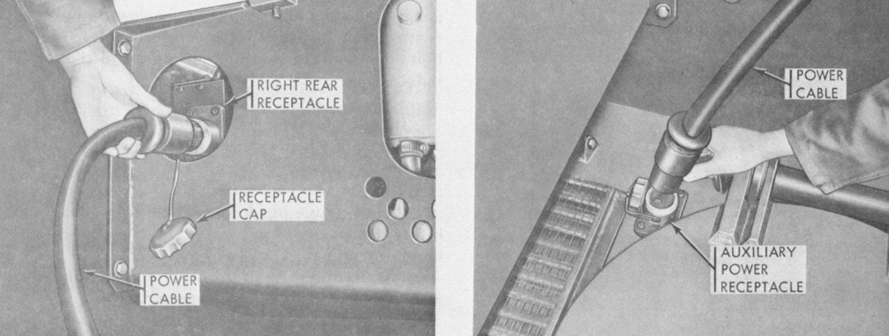
To connect the generator to the vehicle, a receptacle was provided to the right rear of the driver's hatch. (Picture from TM 9-2300-224-10.)
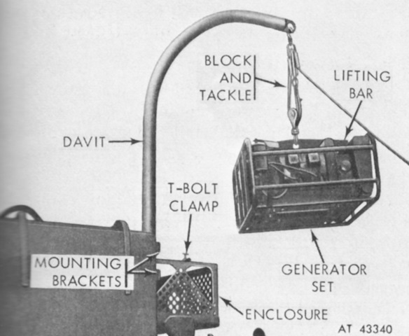
Dismounting the generator from the carrier required the used of the davit normally stowed on the vehicle roof. (Picture from TM 9-2300-224-10.)
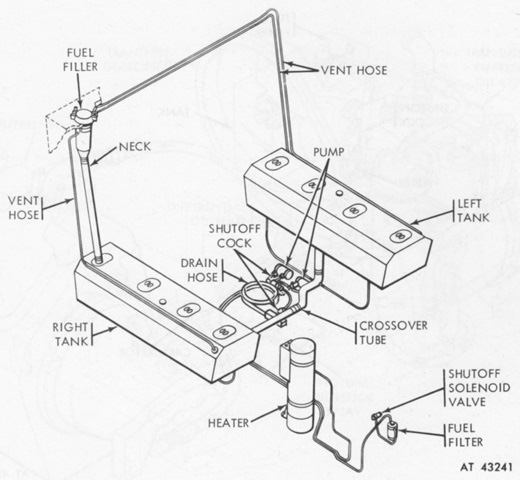
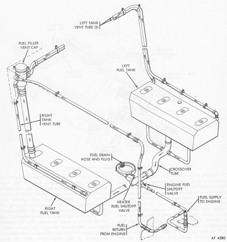
The fuel system differed from the M113 by being composed of two tanks, one placed on each side of the passenger compartment to act as a support for the work tables. (Picture from TM 9-2300-224-10.)
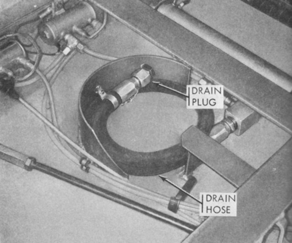
Instead of a simple plug above the left fender for draining fuel like on the M113, the M577 needed to have the rear hull drain plug and floor plate removed so that this hose, normally stowed under the rear floor plate in the personnel compartment, could be fed through the hull drain hole into an appropriate receptacle. The plug on the end of the hose was then unscrewed to drain the tanks. (Picture from TM 9-2300-224-10.)
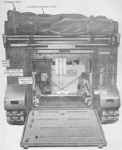
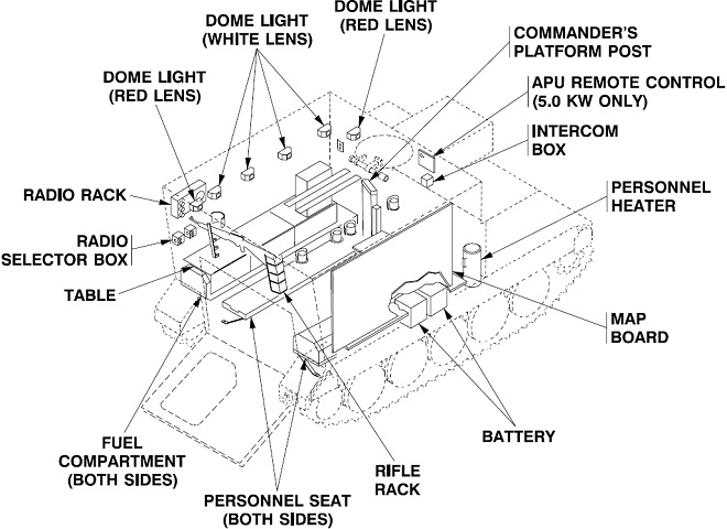
The passenger compartment can be seen here with the tables and personnel seat stowed. Instead of a seat, the commander was provided with a folding platform on which to stand through the roof hatch. The FADAC cable plug was to connect to the field artillery digital automatic computer. When pressed, the admittance switch would sound a buzzer inside the passenger compartment so that the occupants could switch from dome lights to blackout lights before the door was opened. Similarly, the driver's compartment was provided with a blackout curtain that could be secured by snaps and therefore hide light emitted by the dome lights in the rear. (Picture from TM 9-2300-224-10.)
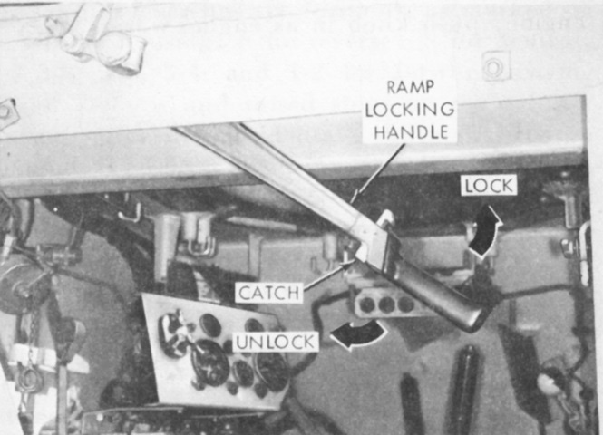
Compared to the M113, the ramp locking handle was moved from behind the driver's right shoulder to the upper beam behind the driver's seat. (Picture from TM 9-2300-224-10.)
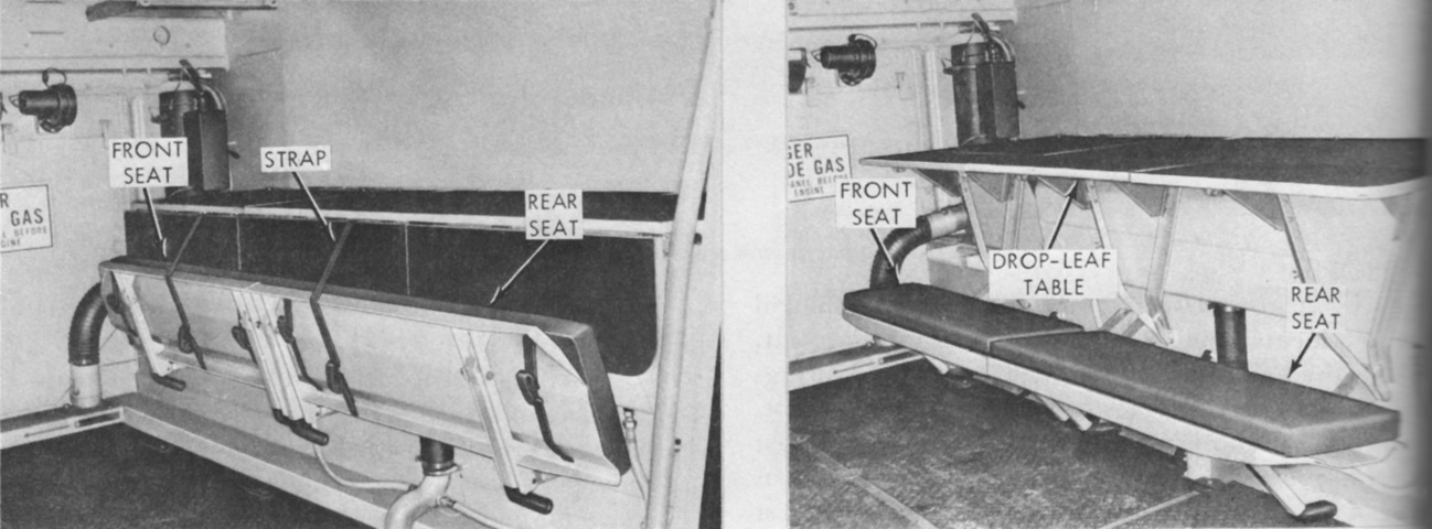
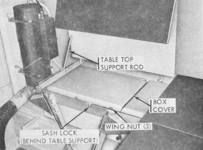
The passenger seats and table are shown here stowed and extended. The table drop leaf could be used as a backrest when the seats were in use. A map board could be mounted on the wall above the table or removed for installation in the covered extension when erected. The personnel heater can be seen in front of the table. (Picture from TM 9-2300-224-10.)
The battery box was located under the forward right table. The personnel heater is in front of the table, and its flexible tubing leading to the floor ducts can be seen. (Picture from TM 9-2300-224-10.)
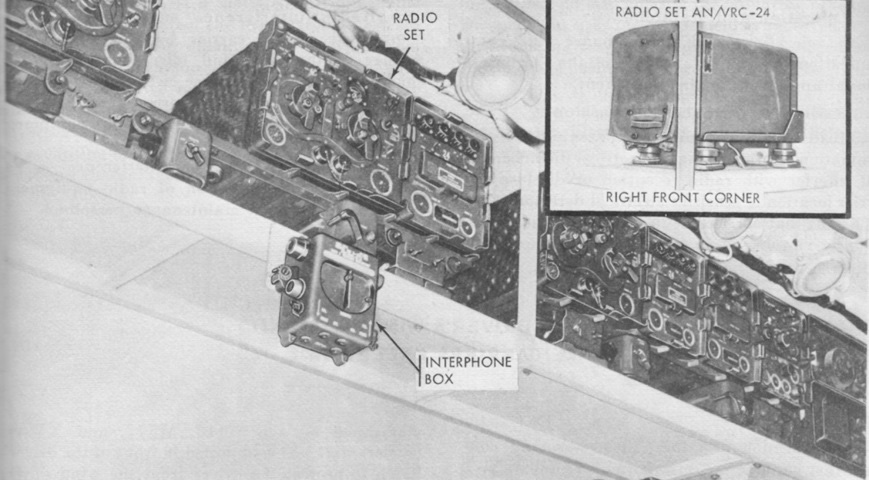
Various radio suites could be installed, but a typical setup is shown here, on racks near the left-side ceiling. (Picture from TM 9-2300-224-10.)
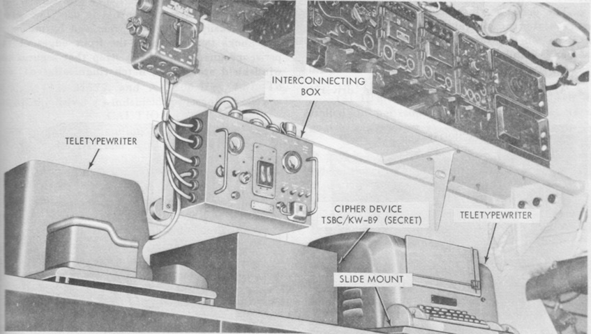
Teletypewriters were also commonly carried. Radio sets can be seen on the rack above. (Picture from TM 9-2300-224-10.)
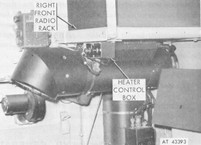
An electronic equipment heater was provided in addition to the personnel heater in order to try to keep the personnel compartment above 40°F (4°C) when extremely cold temperatures were encountered. The equipment heater was identical to the personnel heater except for the air circulating system, which was a single air outlet elbow that could direct the heated air downward. The personnel heater used a flexible tube to direct the air into a floor-mounted duct that expelled the air into the driver's and personnel compartments. (Picture from TM 9-2300-224-10.)
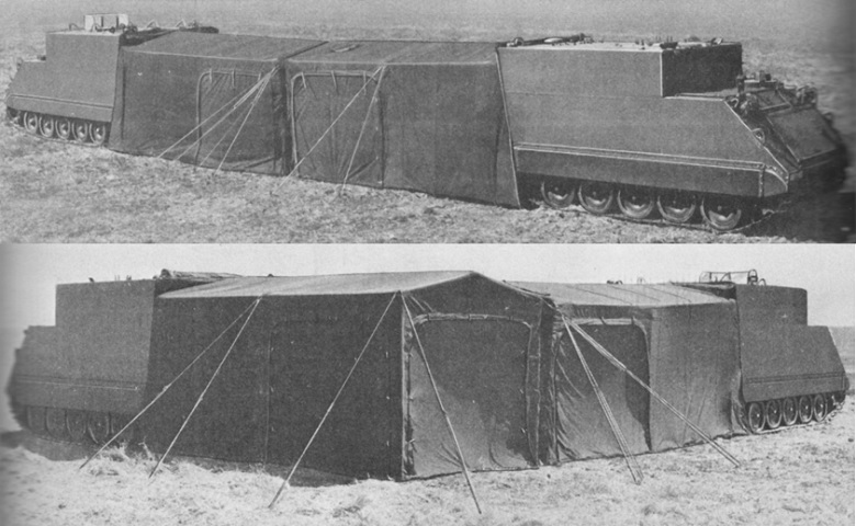
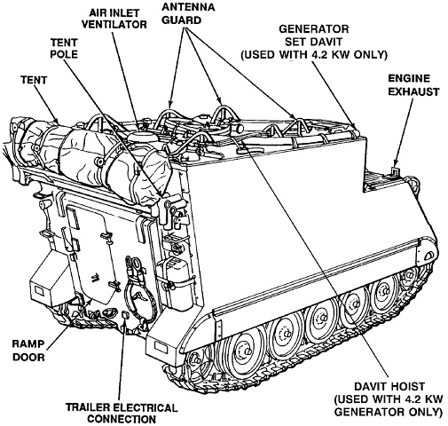
The covered extensions are shown here erected. The extensions could connect different vehicles from the side or from the end. (Picture from TM 9-2300-224-10.)
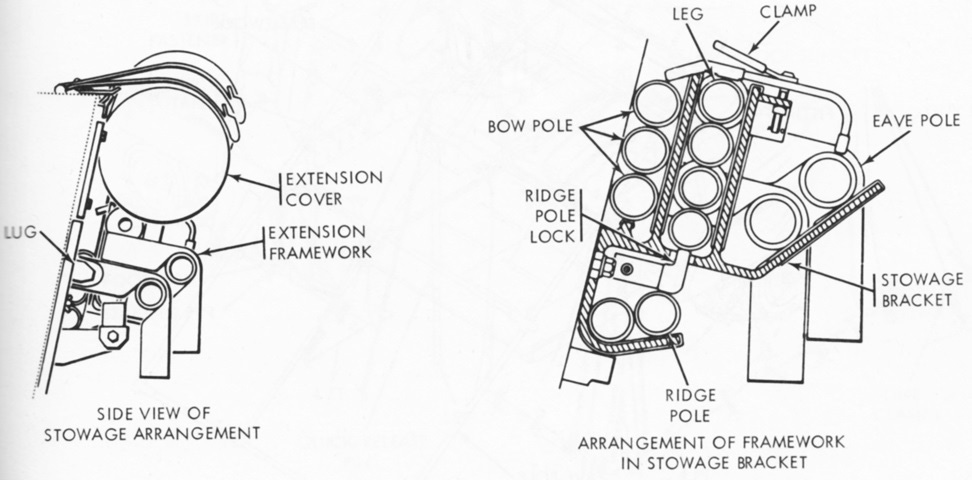
The extension framework and cover were to be stowed on the rear of the carrier in the above manner. (Picture from TM 9-2300-224-10.)
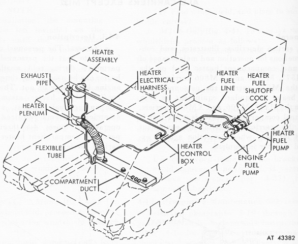
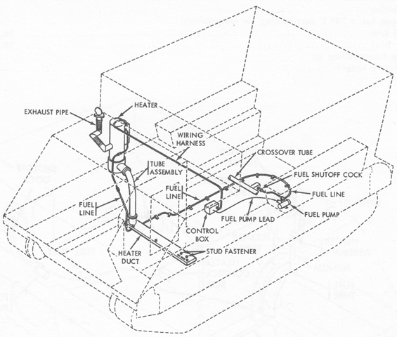
The personnel heater and its fuel system is diagrammed here. (Picture from TM 9-2300-224-10.)

This interesting image shows the size of the M577A1 compared to both its progenitor on the right and an M48A5 tank on the left. Its M113 parentage is obvious; the passenger compartment has been raised to better accommodate command staff functions. The auxiliary generator housing is to the driver's right, and antenna guards are visible on the roof of the vehicle. Under the guard to the driver's hatch's left rear is the external handle for activation of the vehicle's fire suppression system, and above this are two antenna mounting brackets. (Photo by Richard S. Eshleman.)
The fuel system for the diesel engine is diagrammed in this picture. (Picture from TM 9-2300-257-10.)
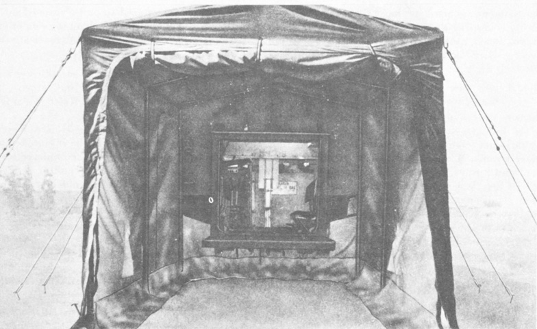
A look into an erected covered extension is provided here. (Picture from TM 9-2300-257-10.)
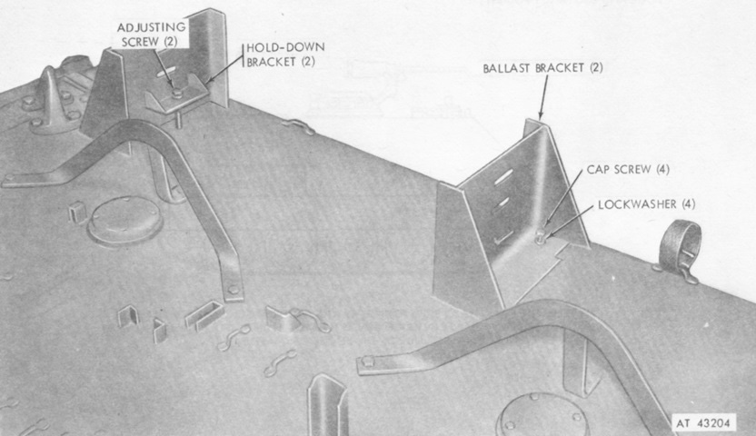
To prepare the M577A1 for water operations, a data plate was provided above the rear engine access door that specified the correct amount of ballast to install. The ballast was held in place by two brackets that were secured to the top left roof as shown. (Picture from TM 9-2300-257-10.)
A schematic of the personnel heater and its fuel system is drawn here. (Picture from TM 9-2300-257-10.)
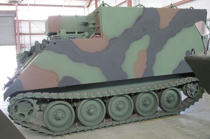
The high passenger compartment is easily seen in this profile view. The raised idler wheel indicates that this vehicle has the improved suspension of the M113A2.
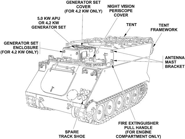
Details of the front of the vehicle are sketched here. (Picture from TM 9-2350-261-10.)
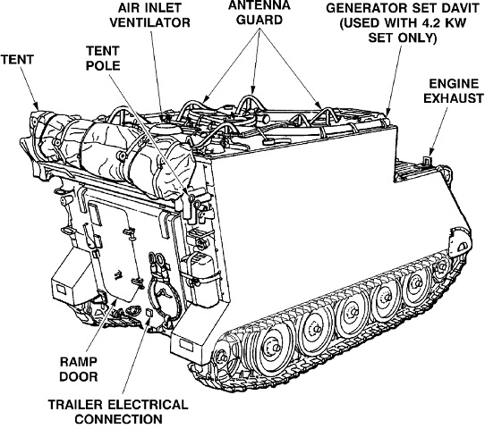
Rear stowage and details are shown in this image. (Picture from TM 9-2350-261-10.)
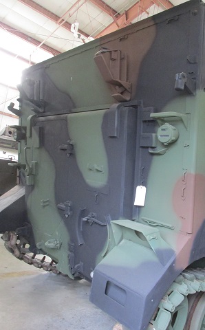
The rear of the vehicle is shown here without stowage, allowing the racks and brackets to be more easily seen.
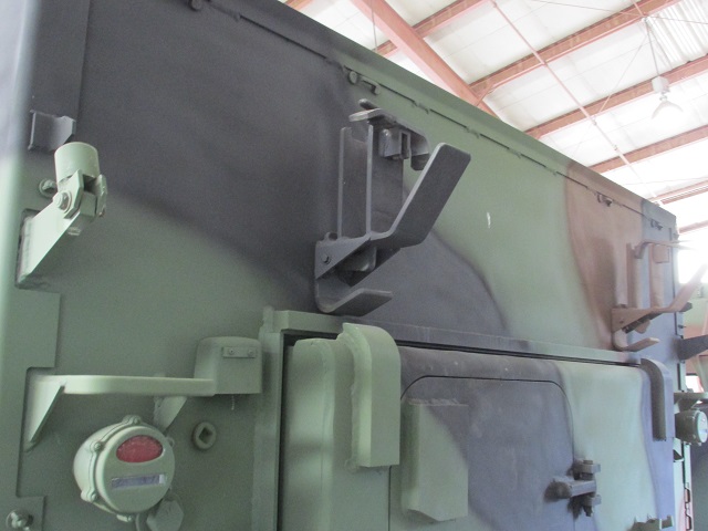
A closer view of the tent stowage rack is provided in this image. Above and outboard of the taillights are fittings in which the tent frame was inserted.
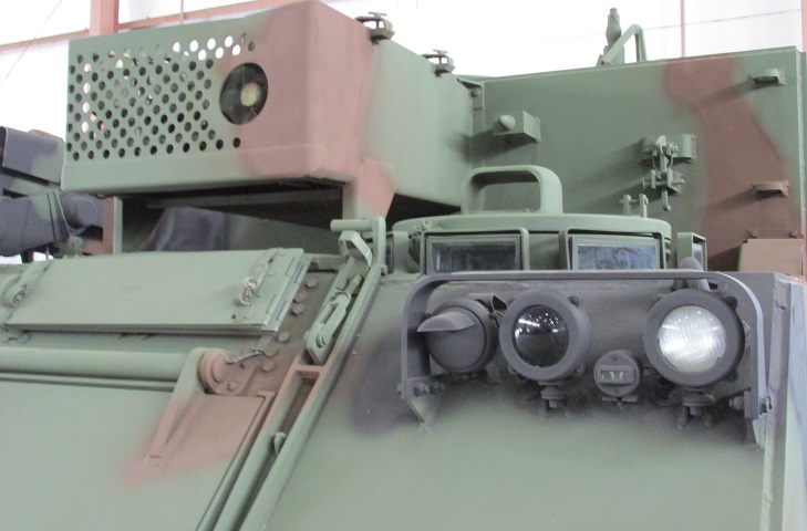
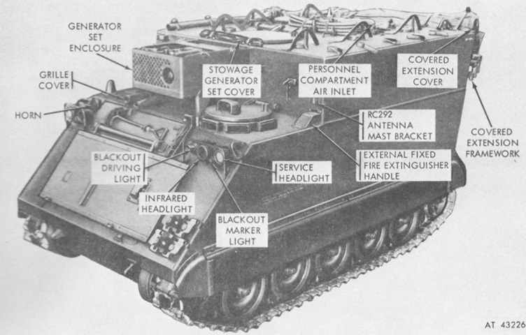
The enclosure for the 4.2 kilowatt generator set was above and behind the driver's right. The trim vane control handle can be seen on the front slope in front of the driver, although the trim vane itself is not mounted on this vehicle. Inboard of the trim vane control handle is the engine access hatch.
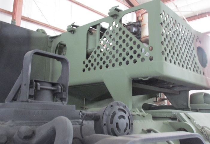
This picture shows the opposite side of the generator set enclosure. The round horn is visible in the foreground, and behind is the engine exhaust inside its guard.
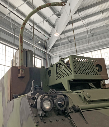
The davit used to dismount the generator is seen installed.

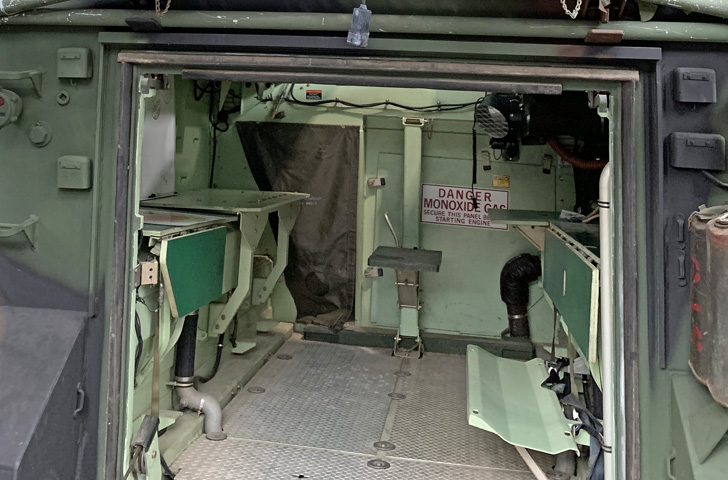
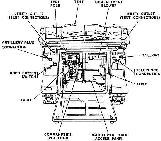
A view into the open passenger compartment is provided here. (Picture from TM 9-2350-261-10.)

The internal arrangement of the rear compartment is illustrated in this ghosted image. (Picture from TM 9-2350-261-10.)
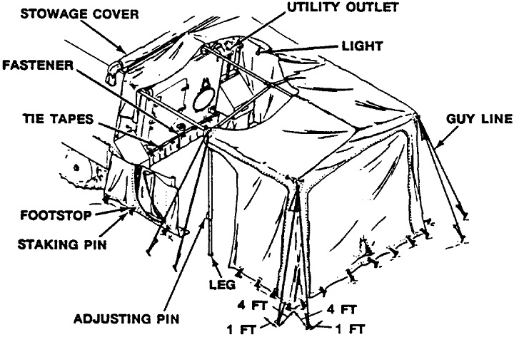
The rear tent has been erected, and details of the structure are shown. (Picture from TM 9-2350-261-10.)
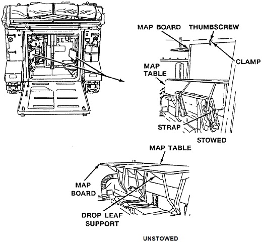
The map board and table are shown stowed and unstowed. (Picture from TM 9-2350-261-10.)
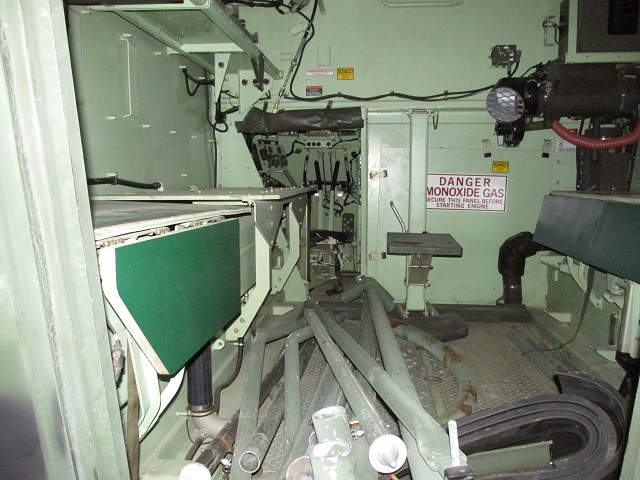
The open rear door on this carrier allows a view of its interior, where the tent frame has been laid. The personnel heater is mounted in the front right corner, the commander's platform is at the front center, and the driver's position can be seen to the front left. The radio rack is at the upper left above the stowed tables.
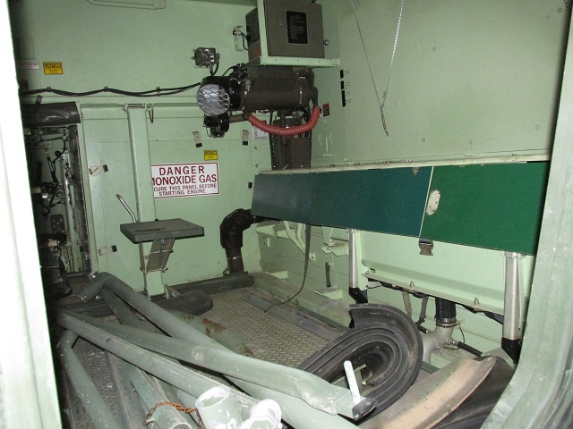
The opposite side of the carrier shows ample space where a map board could be mounted.
The tent posts have been removed from the interior, and on the right a personnel seat has been lowered, although it is missing its cushion. The driver's blackout curtain is unrolled.

A look up at the ceiling shows the numerous dome lights and the darker commander's hatch to the front.
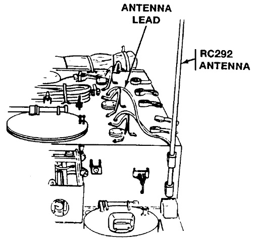
An RC 292 ground whip antenna could be mounted via two brackets to the driver's left. (Picture from TM 9-2350-261-10.)
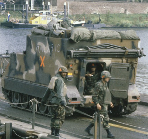
The soldier in this vehicle is looking through the door in the rear hatch. The erectable tent is rolled up on the rear roof of the vehicle, and its supporting posts are stowed above the rear entry hatch. There are two small boxes just to the left of the rear hatch; the top one covers a utility outlet, and the bottom is a door buzzer switch. Just below and inboard of the left taillight group is a plug for the Field Artillery Digital Automatic Computer. This vehicle belongs to 1st Cavalry Division and is taking part in Exercise REFORGER '83. (Picture taken 20 Sep 1983 by SSG. Ronald Lewis; available from the National Archives.)
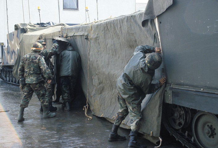
The tents on the backs of two vehicles being used as the tactical operations center for the 32d Separate Infantry Brigade (Mechanized) of the Wisconsin National Guard are in the process of being connected. This was during REFORGER '86. (Picture taken 22 Feb 1986 by SFC Nathaniel H. Mcbride; available from the National Archives.)
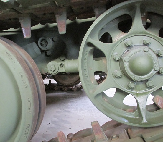
The rear road wheel and idler are highlighted here. A shock absorber can be seen angling down behind the rear road wheel, and the track tension adjuster reaches horizontally back to the idler wheel. To increase track tension, grease was added to the adjuster via the small inset nipple near the mounting screw. To decrease track tension, grease was let out of the bleed valve on the underside of the adjuster. The adjuster could account for 17" (43cm) of range before adding or removing track shoes became necessary.
The RISE changes that differentiate the M577A3 are mostly internal. (Picture from TM 9-2350-277-10.)
The rear of the carrier is drawn here. (Picture from TM 9-2350-277-10.)
A glimpse into the passenger compartment is provided here. (Picture from TM 9-2350-277-10.)
The interior layout was very similar to earlier versions. (Picture from TM 9-2350-277-10.)
