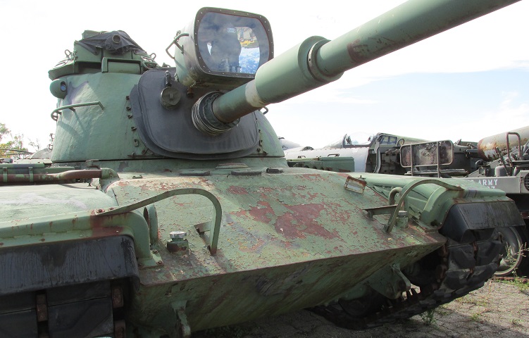
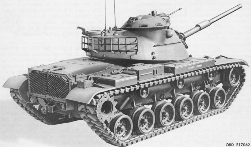
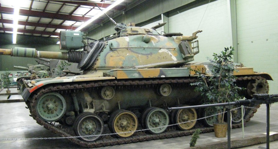
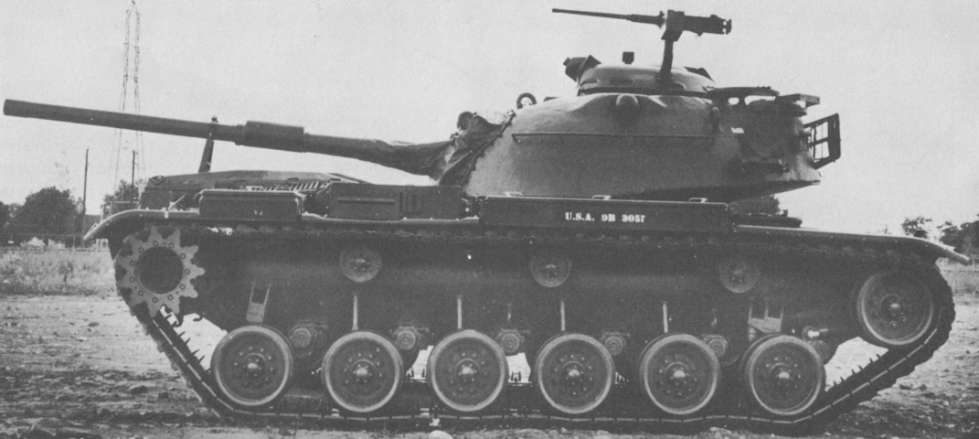
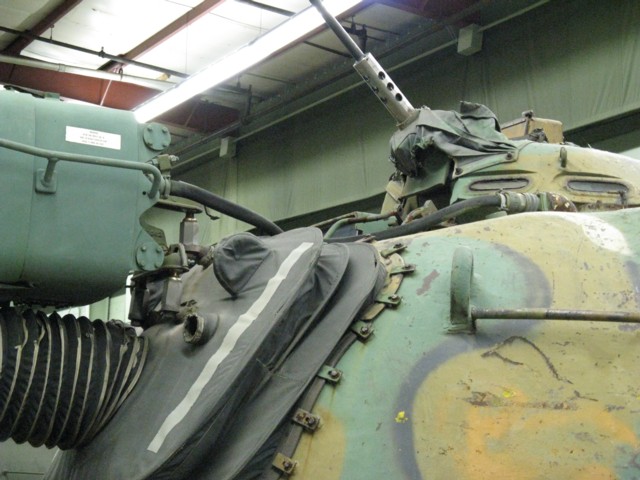
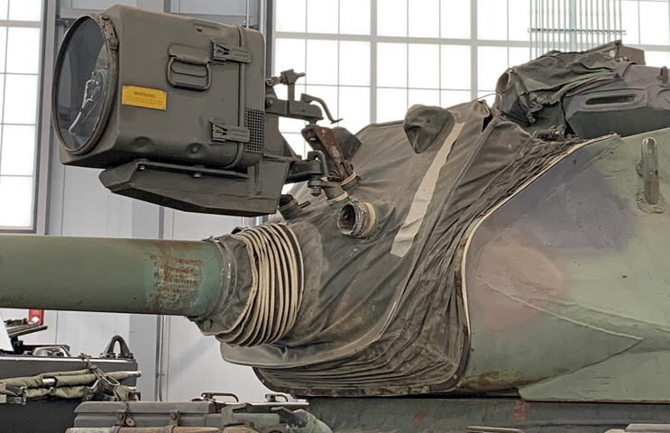
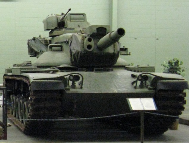
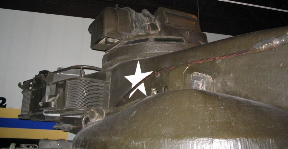
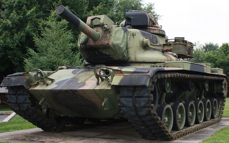
The turret and armament on this vehicle appears similar to that of the M48A5 tank, but the hull is noticeably different. The front hull is wedge-shaped and straight as opposed to M48's rounded bow, and the exhaust pipe for the personnel heater can be seen exiting to the hull's right side, in front of the fender stowage box. The lens for the rangefinder can be seen in the armored blister on the turret side, and the gunner's telescope was provided with a cover in the canvas dust shield. Although obscured from view, this early-production machine has one lifting eye forward on the turret roof and two to the rear. Later turrets had this arrangement reversed.
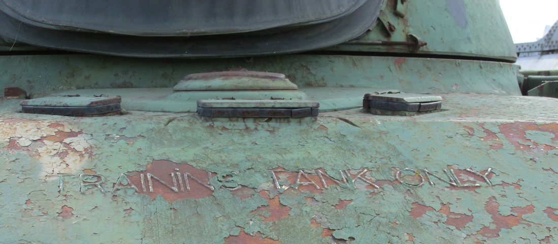
This tank is such early production that it was one of the fifteen afflicted by insufficient hull armor, and was consigned to training.
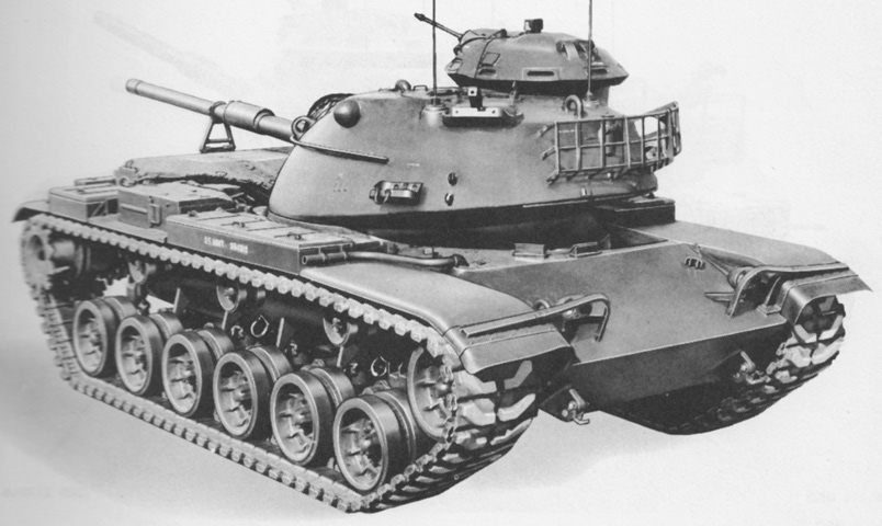
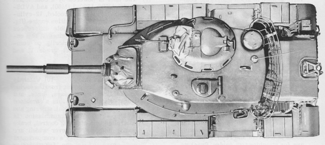
The turret is reversed on this machine, and the gun is secured in its travel lock on the rear deck. (Picture from TM 9-2350-215-10.)
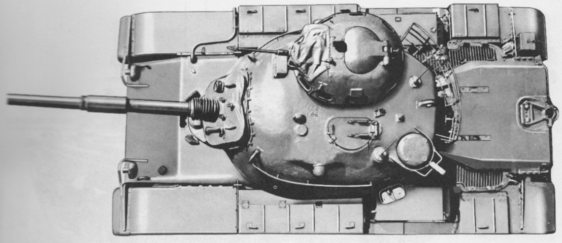
The large size of the cupola is easily seen in this overhead view. The contour of the turret casting around the rangefinder blisters is also easier to discern. The air cleaners for the engine reside on the fenders between the stowage boxes. (Picture from TM 9-2350-215-10.)
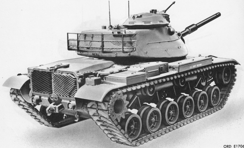
The tank can be seen from the right rear; note the bulge in the turret casting under the commander's cupola. A cutout can be seen in the right-hand exhaust grille for the mounting of a deep-wading exhaust stack. (Picture from TM 9-2350-215-10.)
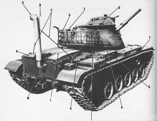
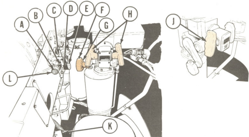
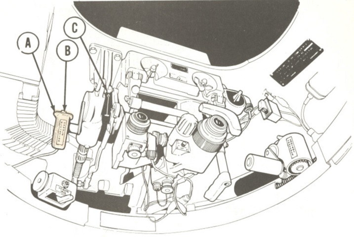
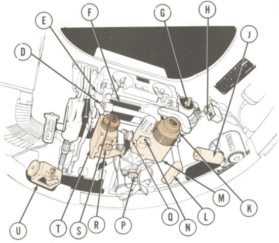
The exhaust stack assembly (A) is mounted on this tank. Other fixtures installed to prepare for wading include: B. Fuel filler vent tube. C. Stack assembly support (left and right). D. Release assembly (left and right). L. Fuel filler vent hose. M. Release cord. The remaining letters are reminders to install or remove specific drain plugs and seals. (Picture from TM 9-2350-215-10.)
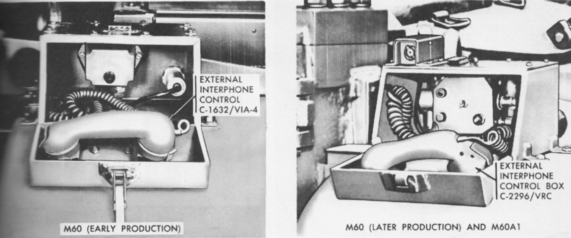
The external interphone was mounted on the right rear fender, and is visible in the previous image. A signal light on top of the interphone's protective box could be flashed by the driver to gain the attention of accompanying infantry, and likewise the infantry could flash a signal light on the driver's control box C-2297/VRC by pressing the handset switch. A 20-foot (6m) self-recoiling cord attached the handset. (Picture from TM 9-2350-215-10.)
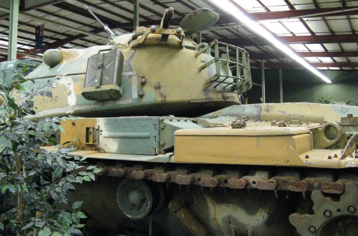
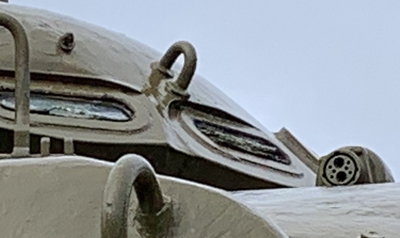
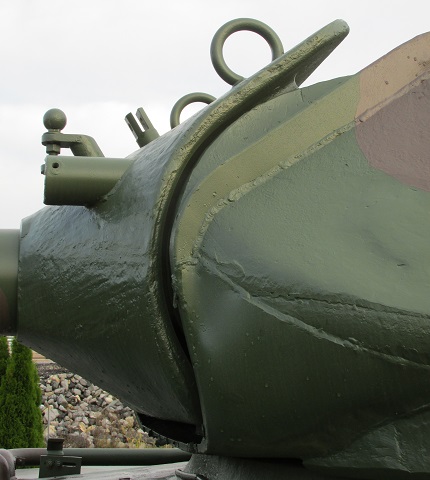
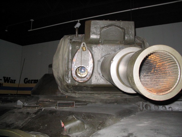
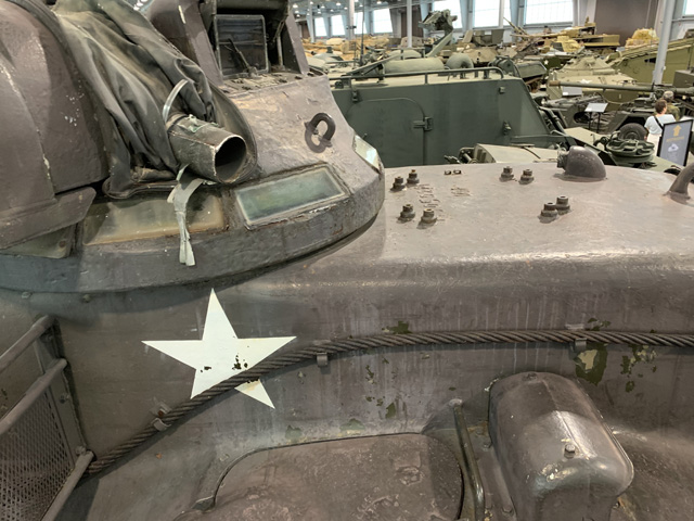
A shallower view of the turret again shows the contour of the side casting as it meets the cupola. The rangefinder blisters and gunner's telescope on this tank have been covered over.
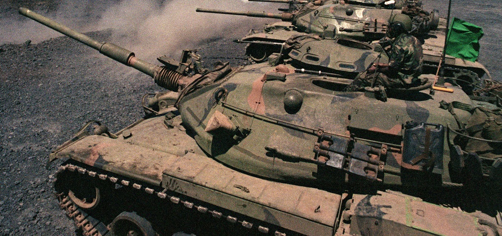
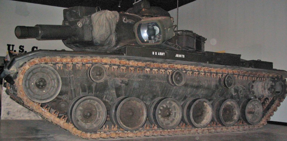
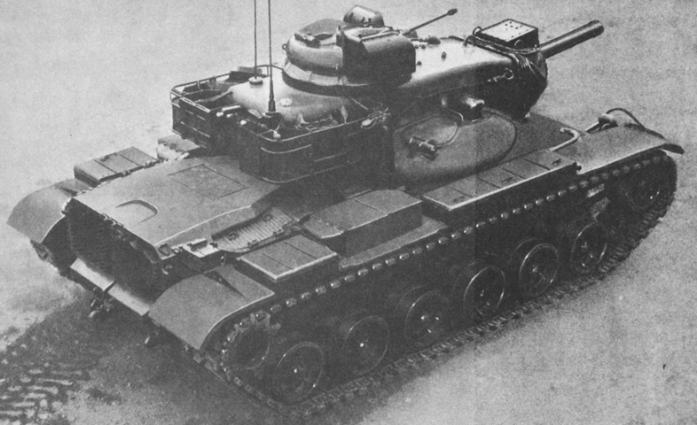
The road wheels on the M60 are forged aluminum, and there are reinforcing struts running around the circumference of each wheel. This vehicle has also been fitted with friction snubbers on the first and last road wheels stations. Both the commander's and loader's hatches are open on this vehicle. On this later-production turret, there are two lifting eyes forward and a single one to the rear.
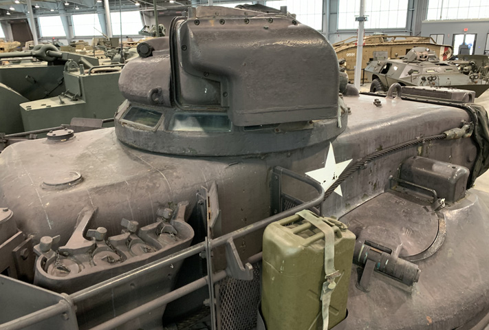
The stowage mount for the xenon searchlight can be seen on the left rear corner of the turret roof; the supports are attached around the turret ventilator blower cover. Side-loading air cleaner boxes are visible on the tank's fender just ahead of the rear stowage box.
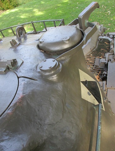
The turret ventilator and searchlight stowage mount are shown here from above. An antenna mount is in front of the ventilator.
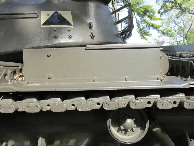
This tank features top-loading air cleaners, as opposed to the machine above.
A top-down view of the top-loading air cleaner is provided here.
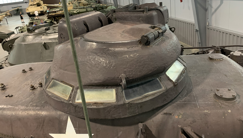
M60 retained the idea of a very large cupola from the M48, and like in the older tank, the .50cal machine gun could be aimed, fired, and reloaded from under armor. Folded forward beside the gunner's periscope is an interrupter bar to prevent the TC from machine gunning the searchlight.
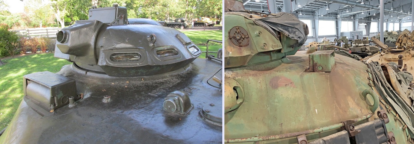
On the left, a closer shot of the M19 cupola shows the contour of the machine gun mount without its canvas dust cover. The gunner's flat-topped periscope housing is in front of the cupola, and mounting posts for the interrupter bar are welded to the roof beside the periscope housing. The power receptacle for the searchlight can be seen in the middle of the turret roof. On the right, the cupola front and gunner's periscope housing are shown from the opposite angle.
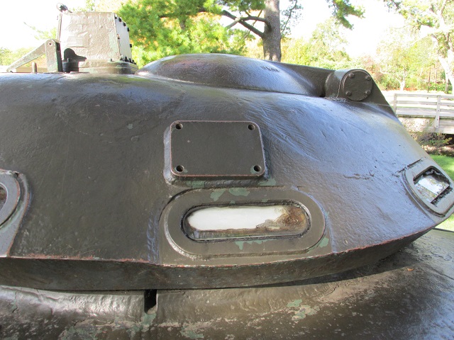
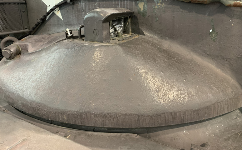
The commander was provided with a door behind his periscope housing. The pad welded to the side of the cupola was a leftover from early production when mounts for the M2HB machine gun were attached to the cupola while the M85 was experiencing production issues.
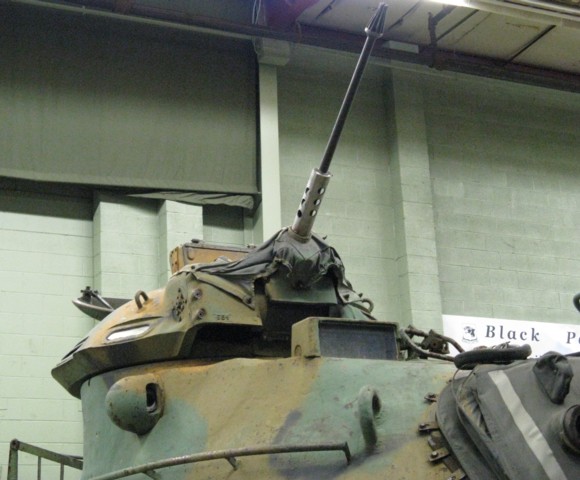
This tank has the external M2HB machine gun mounted on its pedestal. The machine gun mount in the cupola is elevated, but the M85 is not present. Note the absence of shock absorbers for the road wheels. (Picture from Tactical Vehicles.)
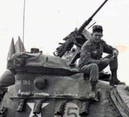
This cupola is traversed to the right to orient the external machine gun toward the turret front. Tank commander Joe Wood is sitting on the gunner's periscope guard. (Picture courtesy Evelyn Wood.)
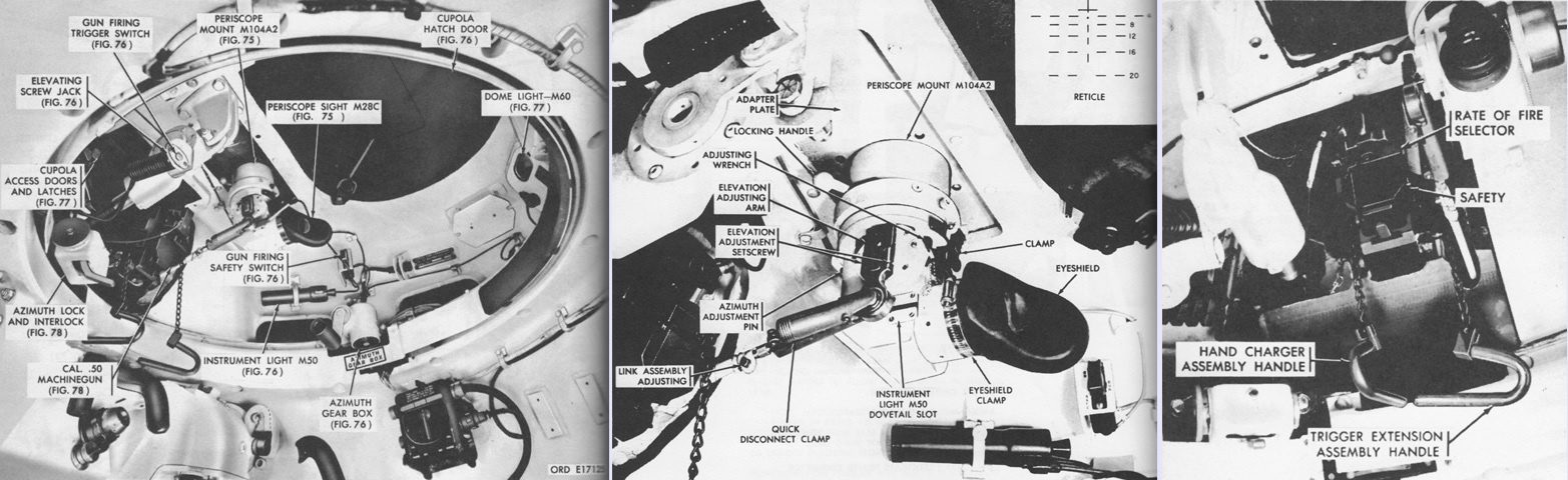
An overall view of the cupola interior is shown on the left. In the center is the periscope M28C and its firing reticle in the upper right corner. The M28C was a 1.5x device with a 48° field of view. At the right are various controls for the M85 machine gun. It had high and low rates of fire of 1,000-1,100 and 350-450 rounds per minute, respectively, and the commander could choose between these with the selector indicated. The hand charger assembly handle and trigger extension assembly handle permitted manual charging and manual firing of the weapon. Note the eyeshield has been removed from the periscope in the right image. (Picture from TM 9-2350-215-10.)
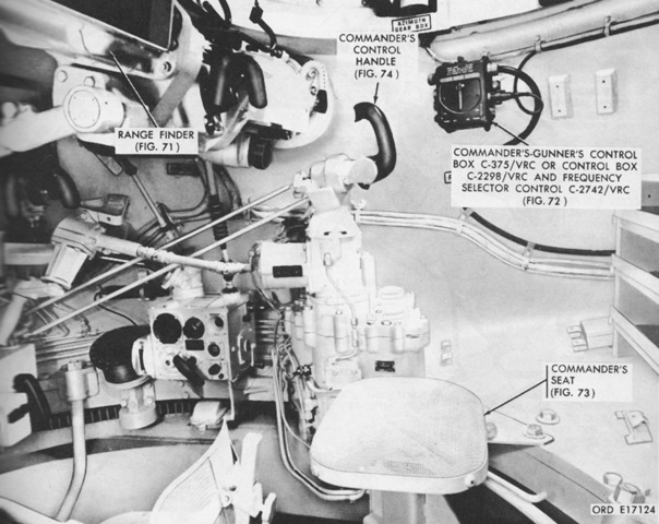
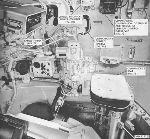
The commander's position in the turret is shown here. He could override the gunner's inputs via his control handle, and use it to traverse the turret, and elevate and fire the gun. On the opposite side of the handle was a magnetic brake actuator that, when squeezed as the commander gripped the handle, allowed the commander to assume control from the gunner. (Picture from TM 9-2350-215-10.)
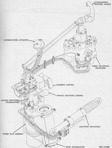
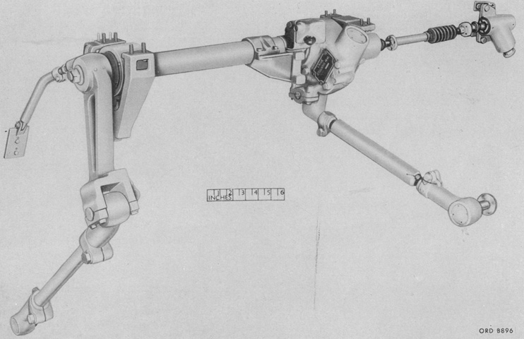
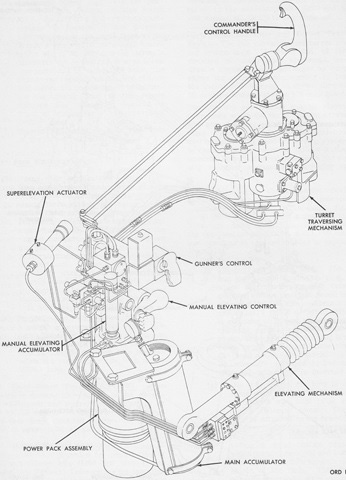
A schematic of the turret traverse and elevation system is sketched in this image. The relationship of the commander's override handle to the gunner's controls and traverse mechanism can be seen. (Picture from TM 9-2350-215-10.)
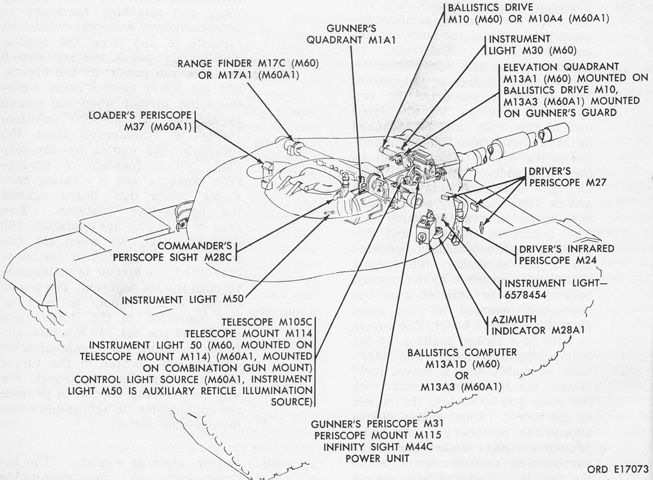
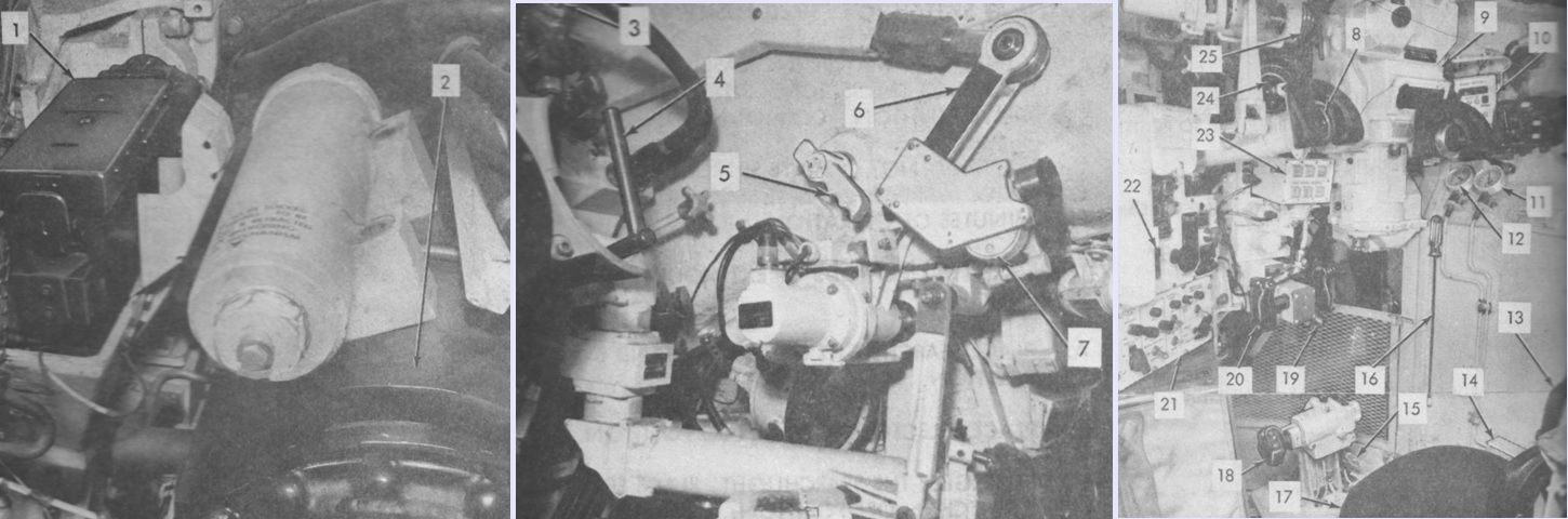
The location of components of the fire control system is the subject of this drawing. (Picture from TM 9-2350-215-10.)
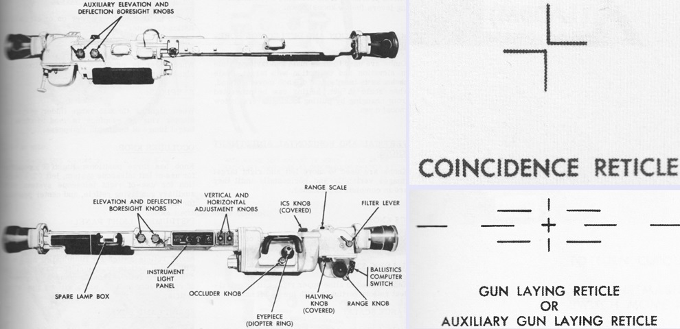
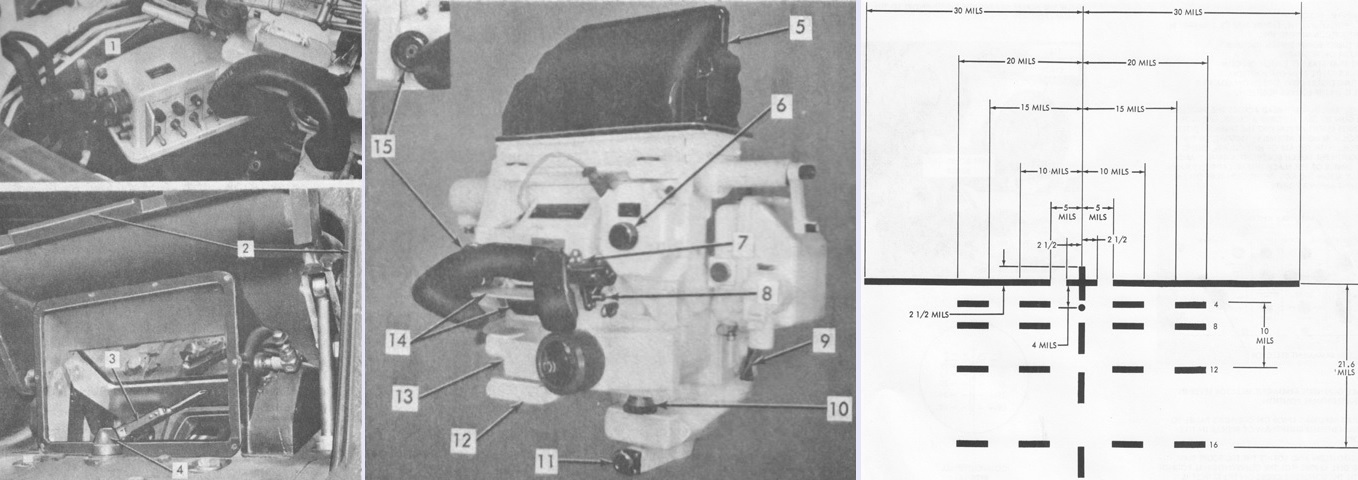
The commander's rangefinder was a coincidence model that did not require the visual acuity of older stereoscopic rangefinders. The commander used the vertical and horizontal adjustment knobs and finally the range knob to align the target images from the left and right lenses until they were in coincidence. Once this occurred the range could be read through the range scale window. The M17C was 84" (213cm) long including the end housing assemblies, 14" (36cm) wide, 12" (30cm) tall, and weighed 149lb (67.6kg) including the end housing assemblies. Its base length was 79" (200cm), magnification was 10x, and its real field of view was 4°. It could provide ranges from 500 to 4,400m. At the right are sketches of its coincidence reticle at the top and the gun laying reticle below. The coincidence reticle was used as a guide to tell if the rangefinder was properly aligned, and would form a cross when this was so. (Picture from TM 9-2350-215-10.)
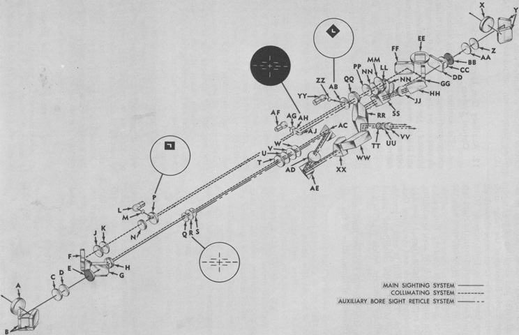
The optical system of the rangefinder M17C is diagrammed here. The system functioned by using the angle variation of light from the target that entered the left and right housing windows. When the images of the target from the separate windows were brought into coincidence to form a single clear image by rotating the range knob, the rangefinder was trigonometrically calibrated to use the resulting angle to display the range to the target. The main gun laying reticle was located in the left-side optical system, and the auxiliary gun laying reticle for emergency use was found in the right-side system. The auxiliary reticle was identical to the main reticle, and could be used if the left-side system was damaged or if an illuminated reticle was needed.
Left main housing assembly optical components: A. End housing window. B. End housing penta reflector. C. End housing wedge. D. Range finder end window. E. Filter. F. Porro reflector. G. Porro reflector. H. Objective lens. J. Correction wedge. K. Correction wedge. L. Right reticle lamp. M. Reticle window. N. Collimator lens. P. Right coincidence reticle. Q. Collective lens. R. Main boresight reticle. S. Collective lens. T. First erector lens. U. Correction wedge. V. Correction wedge. W. Correction wedge.
Right main housing assembly optical components: X. End housing window. Y. End housing penta reflector. Z. End housing wedge. AA. Range finder end window. BB. Filter. CC. Compensator lens. DD. Compensator lens. EE. Prism. FF. Porro reflector. GG. Porro reflector. HH. Prism. JJ. Objective lens. KK. Porro prism. LL. Reticle lens. MM. Reticle lens. NN. ICS wedge. PP. Correction wedge. QQ. Collimator lens. RR. Right ocular prism. SS. Beam splitter prism. TT. Diaphragm. UU. Field lens. VV. Eye lens. WW. Combining prism. XX. Left ocular prism. YY. Left reticle lamp. ZZ. Left coincidence reticle window. AB. Left coincidence reticle. AC. 90 degree prism. AD. Erector lens. AE. 90 degree prism. AF. Reticle lamp. AG. Diffusion disk. AH. Auxiliary boresight reticle assembly. AJ. Reticle mirror. (Picture from TM 9-1240-258-34.)
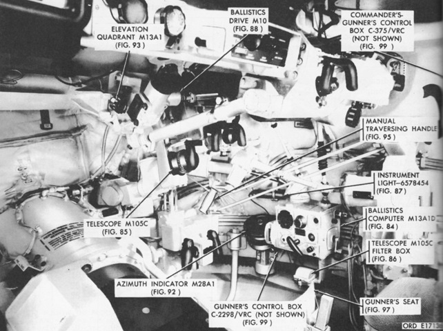
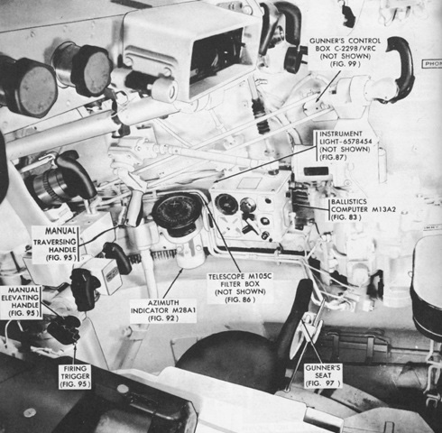
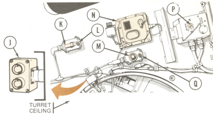
The right side of the gunner's position is labeled in this picture. (Picture from TM 9-2350-215-10.)
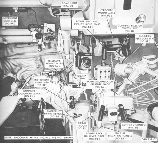
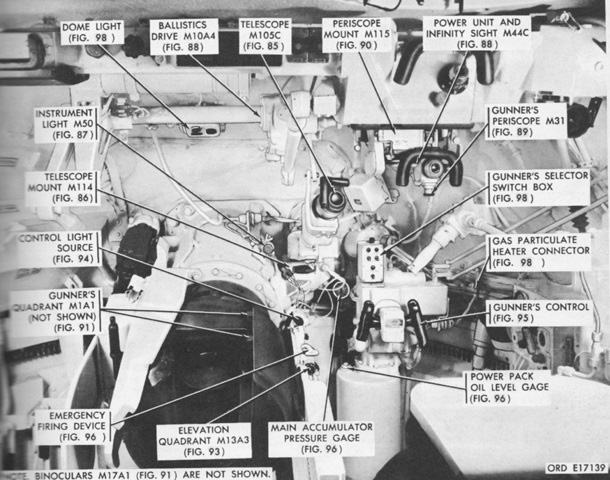
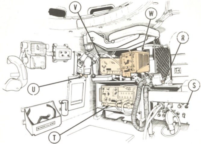
The front of the gunner's position is shown here. The 105mm gun breech is to the lower left of the image. (Picture from TM 9-2350-215-10.)
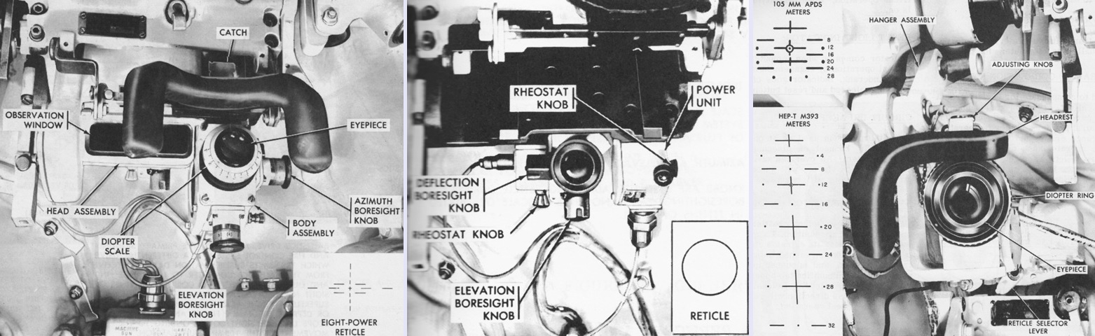
The gunner's periscope M31 is seen on the left. It contained an 8x optical system with an 8° field of view and a unity observation window with a 32°32' horizontal and 5°48' vertical field of view. The center image shows the infinity sight M44C used with the coaxial machine gun. It projected an illuminated 20-mil diameter ring onto the unity power optical system of the periscope M31. The periscope has been removed for clarity in this picture. On the right is the gunner's telescope M105C, which provided 8x magnification and a 7°30' field of view. The gunner could switch between reticles for APDS and HEP-T. The horizontal lines represented leads of 5 mils, and range was numbered in hundreds of meters. (Picture from TM 9-2350-215-10.)
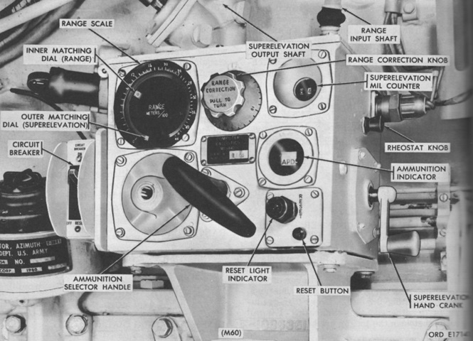
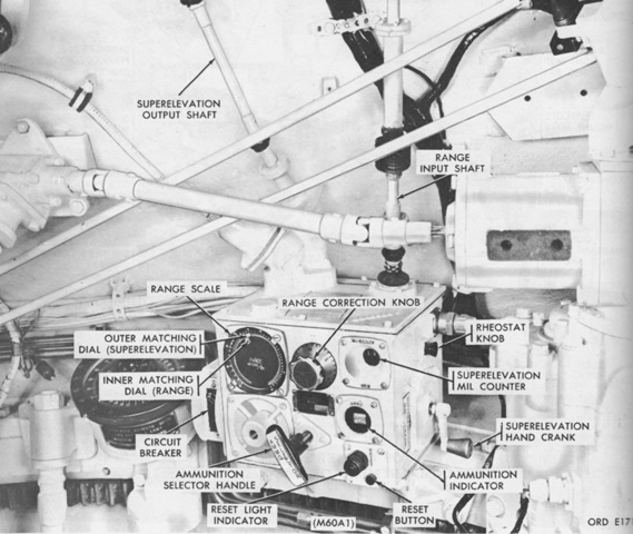
A closeup of the ballistic computer M13A1D is provided in this picture. The range input shaft transmitted range information from the commander's rangefinder, and the superelevation output shaft likewise transmitted superelevation information from the computer to the ballistic drive. The superelevation handcrank allowed manual input of superelevation data into the computer. The range scale was graduated from 0 to 4,400m in 100-m increments. The range correction knob was used to compensate for variable conditions that could affect the gun's performance, such as ambient air temperature and density, gun tube wear, range error, and ammunition variation. It was graduated in intervals of 1% of the range for a total of ±15%. Tube wear was measured by the number of armor-piercing discarding sabot tracer (APDS-T) rounds fired: one round of APDS-T was the equivalent of 40 high-explosive plastic tracer or 1.5 high-explosive antitank tracer rounds. If the tube was new, a correction of -1% was entered. If 10 rounds of APDS-T equivalent had been fired, the correction was 0%, 20 rounds was +1%, 30 rounds was +2%, 40 rounds was +3%, 50 rounds was +4%, 80 rounds was +5%, 90 rounds was +6%, 110 rounds was +7%, 130 rounds was +8%, 150 rounds was +9%, 170 rounds was +10%, and 190 rounds and above was +11%. The inner matching dial indicated the same range as the rangefinder when the correction was 0%, and indicated different ranges depending on the correction factor. The outer matching dial could be manually operated by the superelevation handcrank or electrically operated by the computer, and rotated between the static range scale and the inner matching dial. The M13A1D differed from the M13A1C found in the 90mm gun tank M48A2C by only using three superelevation cams versus the M13A1C's six, and consequently no spare cams box was provided. Also, the M13A1D was mounted directly to the turret, while the M13A1C was provided with a mounting bracket. (Picture from TM 9-2350-215-10.)
The ballistic drive M10 is isolated here. It served as a differential drive that transmitted superelevation data from the ballistic computer to the rangefinder and gunner's periscope to correct the lines of sight for a given ammunition and range. Without superelevation data, the M10 acted as a solid linkage to elevate or depress the rangefinder's and gunner's periscope's lines of sight to correspond with movement of the 105mm gun. (Picture from TM 9-1220-220-35P.)
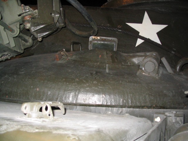
The loader had a D-shaped hatch to the left of the M19 cupola, and another interrupter bar protected the searchlight when it was stowed on the left rear of the turret.
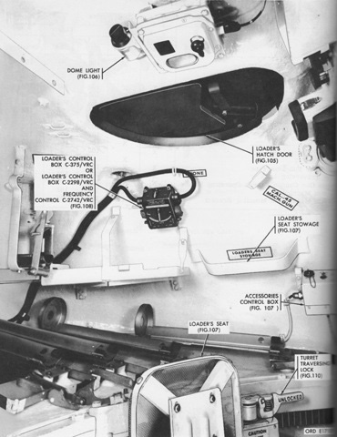
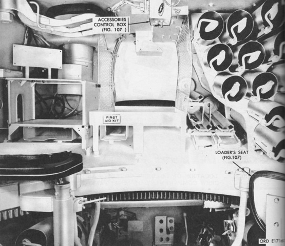
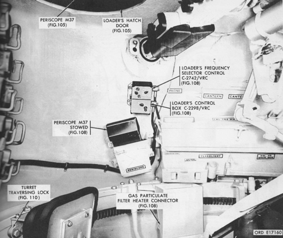
The left rear of the turret under the loader's hatch is illustrated here. (Picture from TM 9-2350-215-10.)
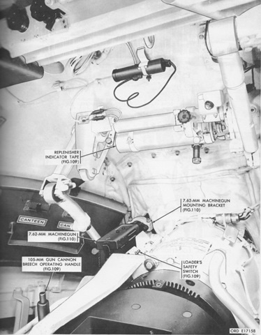
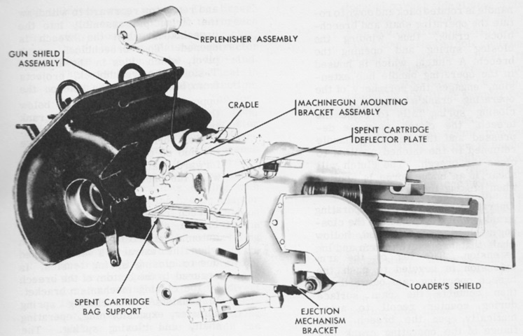
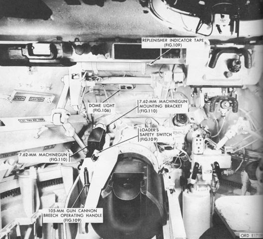
The forward portion of the loader's position is the subject of this picture, and the 105mm gun breech dominates the lower part of the image. The replenisher indicator tape was used to judge the amount of hydraulic oil in the replenisher; if one side of the tape had a rough edge while the other was smooth, the amount of oil was sufficient. If both edges of the tape were rough, the replenisher needed additional oil. If both edges were smooth or there were long notches on each side, the replenisher needed bled or drained. (Picture from TM 9-2350-215-10.)

A stowage socket for the .50cal M2HB machine gun was welded to the turret rear. Another antenna mount is visible on the turret roof to the right of the lifting eye.
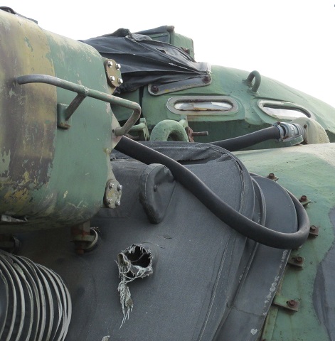
Details of the xenon searchlight mount and power cable can be seen in this image. The visible opening in the canvas dust cover was for the coaxial machine gun.
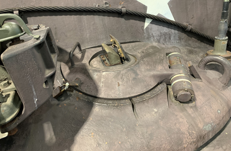
The searchlight receptacle is uncapped on this tank, and the interrupter bar is erected.
Another example of the plugged-in searchlight is provided here. The forward turret lifting eye can be seen behind the searchlight.
The driver's hatch was surrounded by a semicircle of three M27 periscopes, and an M24 infrared periscope could be fitted in his hatch door. When driving with the hatch open, it was first necessary to remove and stow the center periscope M27 so that it did not obstruct forward vision.
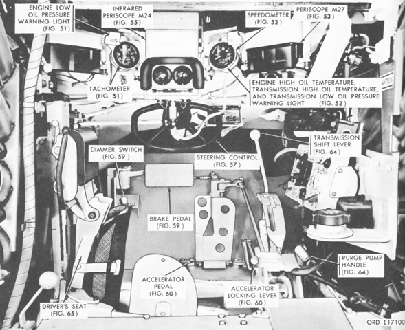
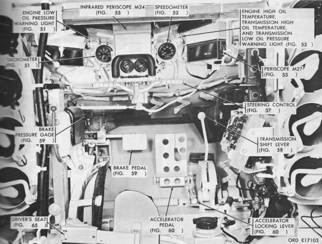
The front of the driver's compartment is labeled in this picture. For clarity, his seat is shown in the dumped position. The purge pump handle was used to purge the fuel lines and pumps of air after the vehicle had been sitting for a period of time. (Picture from TM 9-2350-215-10.)
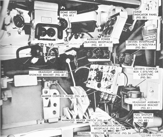
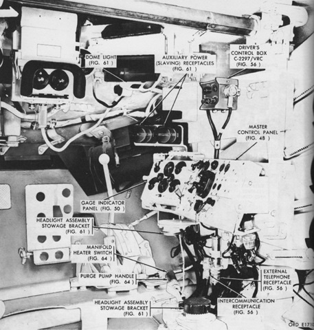
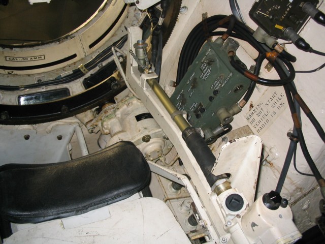
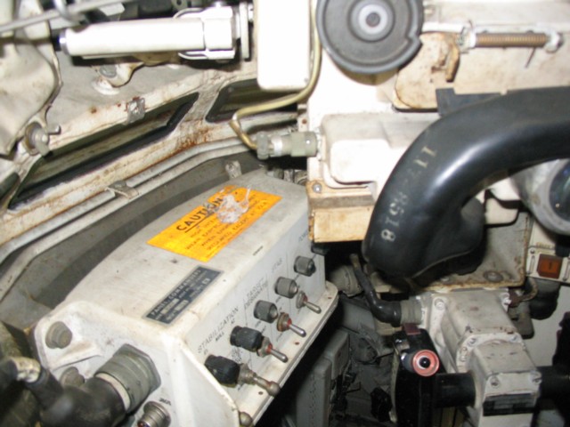
The right side of the driver's position is shown here. The control box C-2297/VRC to the right had the signal light that infantry using the external interphone could flash. (Picture from TM 9-2350-215-10.)
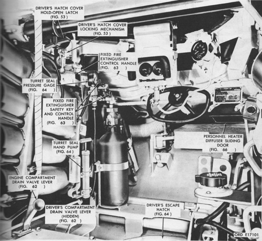
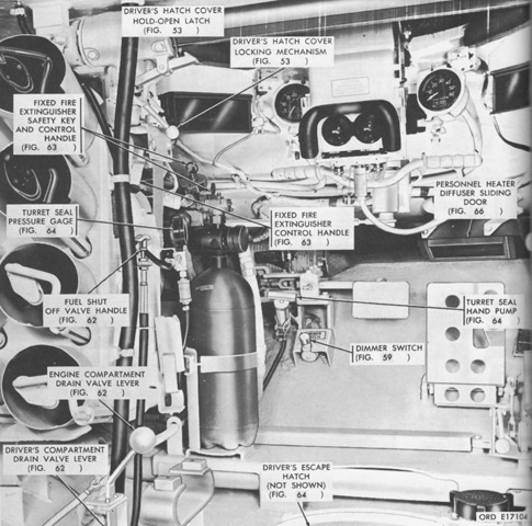
Ammunition stowage tubes can be seen in this view of the left side of the driver's compartment. The turret seal hand pump and pressure gage were used when preparing the tank for deep-water fording or during chemical attack. Normal pressure in the seal was 0psi, but under the above two conditions it was to be inflated to 25psi (1.8kg/cm²). During a combat situation while fording the pressure could be decreased to 5-7psi (.4-.5kg/cm²) to permit the turret to traverse. (Picture from TM 9-2350-215-10.)
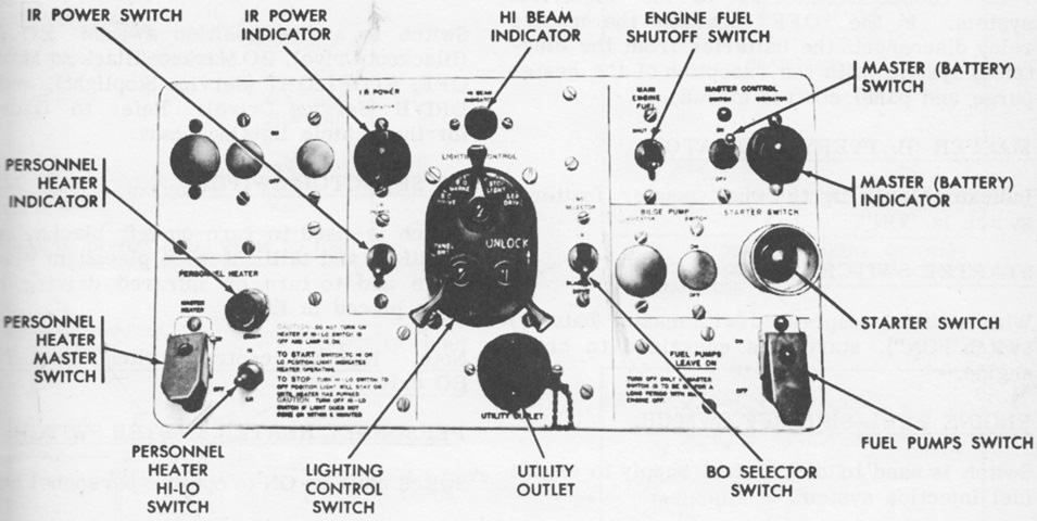
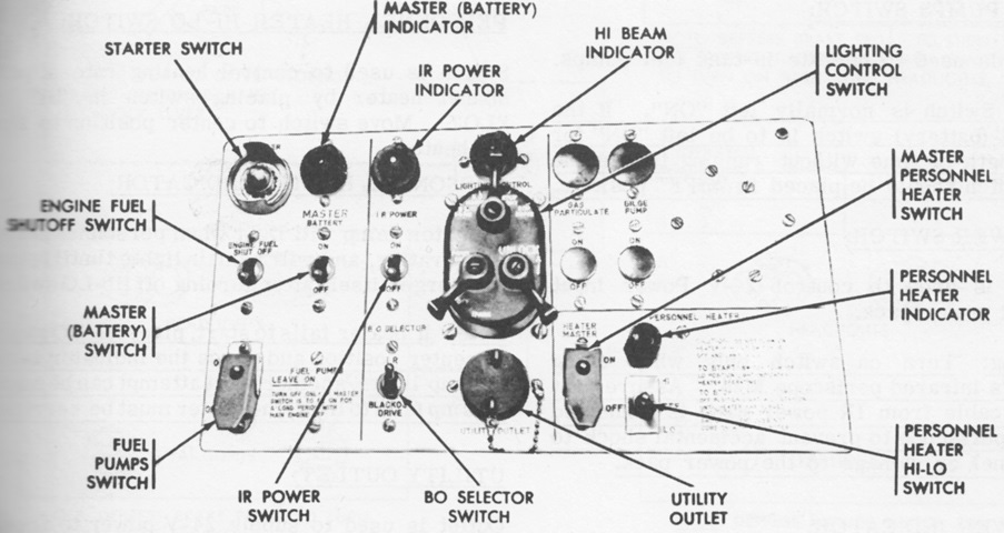
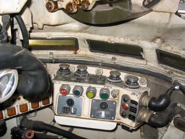
The driver's master control panel is detailed in this image. (Picture from TM 9-2350-215-10.)
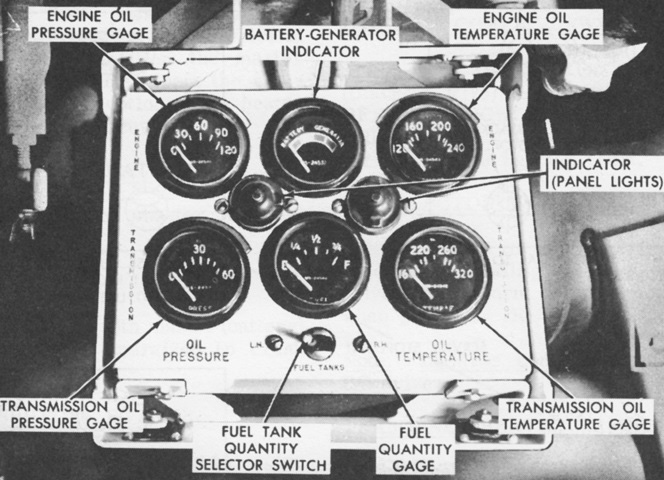
The gage indicator panel was mounted above the master control panel. (Picture from TM 9-2350-215-10.)
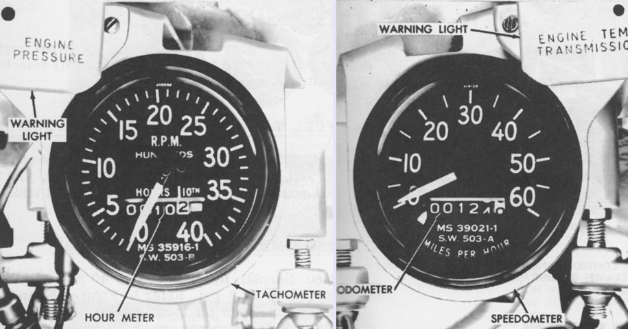
The tachometer/hourmeter and speedometer/odometer were to the driver's front. The hourmeter timed engine operation based on 2,025rpm per hour: that is, one hour rolled over if the engine ran at 2,025rpm for one hour. Thus, if the engine was run for one hour at 1,350rpm, the hourmeter would advance by ⅔ of an hour. The warning light by the tachometer indicated when the engine's oil pressure was low, and the warning light by the speedometer advised of high engine and transmission oil temperature and low transmission oil pressure. (Picture from TM 9-2350-215-10.)
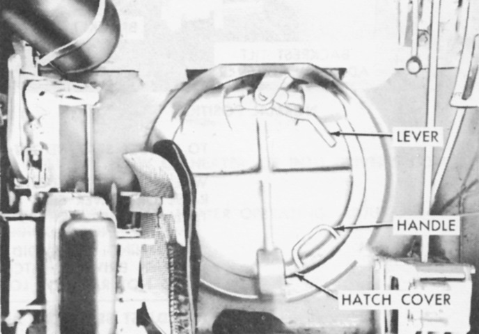
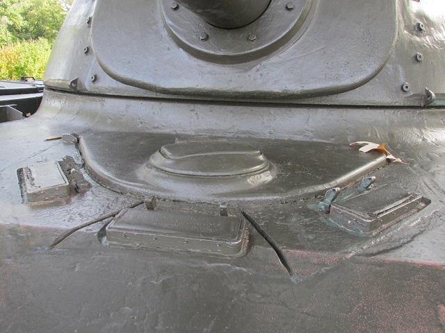
The driver had an escape hatch in the hull floor under his seat. The seat is in the dumped position in this image. To release the hatch, the lever was pulled towards the hatch cover's center, allowing the hatch to fall away. (Picture from TM 9-2350-215-10.)
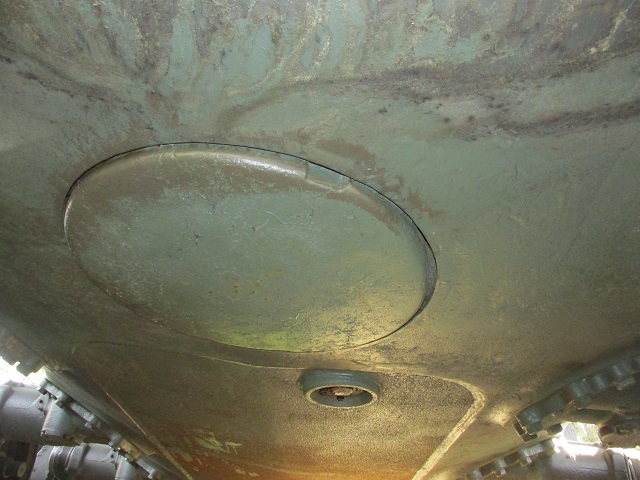
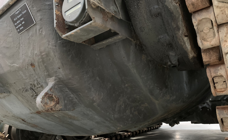
The position of the escape hatch is seen here on the hull underside.
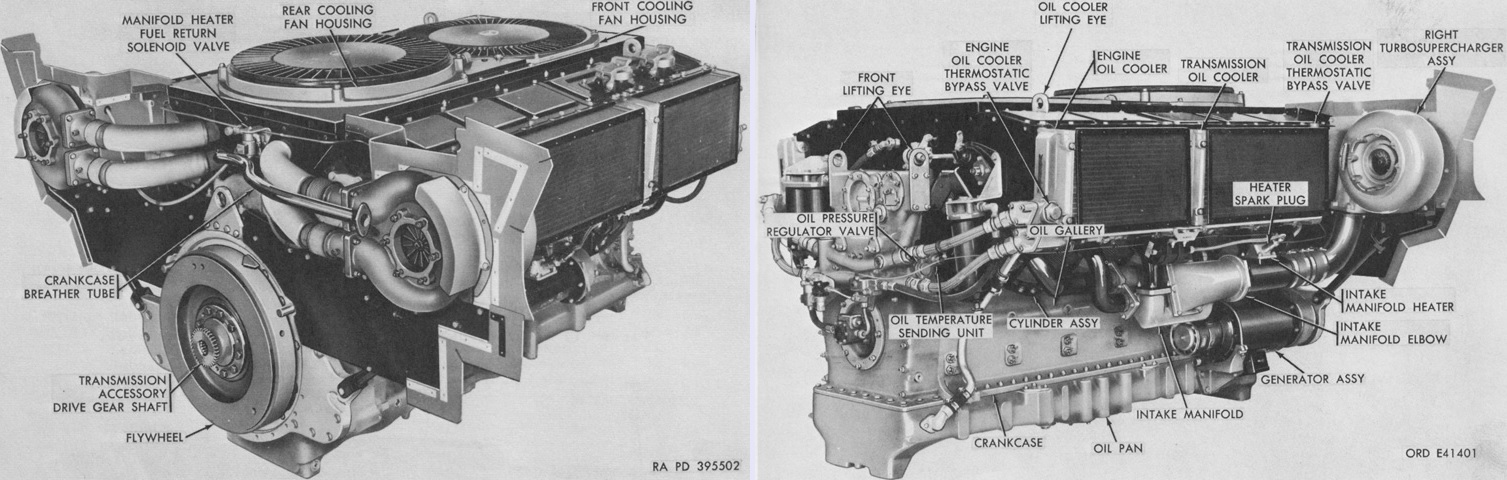
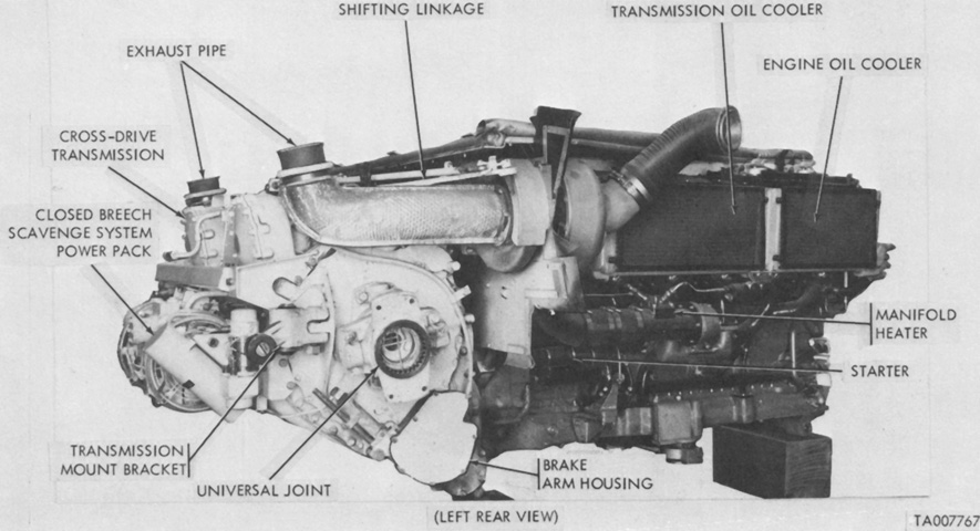
The AVDS-1790-2 engine is displayed from the left rear and from the right front on the left and right, respectively. The damper end of the engine was denoted as the front, with the flywheel being at the rear. Right and left were determined by looking at the engine from the front toward the rear. The cylinders were numbered 1-6 on each side from front to rear, and firing order was 1R, 2L, 5R, 4L, 3R, 1L, 6R, 5L, 2R, 3L, 4R, and 6L. (Picture from TM 9-2815-200-34.)
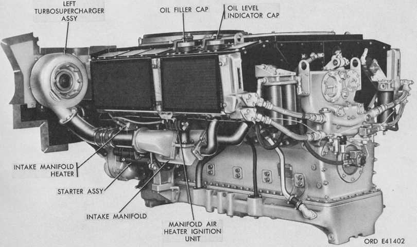
The engine's left front side is labeled here. Including the shroud, it was 70.60" (179.3cm) long to the transmission adapter, 88.37" (224.5cm) wide, 45.97" (116.8cm) high, and weighed 4,527lb (2,053kg) dry with accessories. Its compression ratio was 16:1, and it held 18 gallons (68L) of oil. (Picture from TM 9-2815-200-34.)
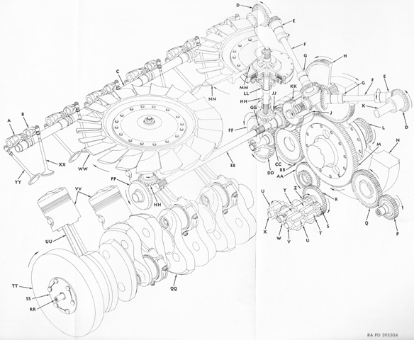
The major working parts are sketched in this diagram. A. Intake valve rocker arm assembly. B. Exhaust valve rocker arm assembly. C. Left camshaft assembly. D. Camshaft driven gear. E. Camshaft drive gearshaft. F. Camshaft drive shaft. G. Camshaft drive bevel gearshaft. H. Accessory drive gearshaft assembly. J. Fuel injector pump advance assembly. K. Right camshaft assembly. L. Transmission drive gearshaft. M. Accessory drive gear. N. Flywheel. P. Generator drive gearshaft. Q. Generator idler gear. R. Oil pump driven gear. S. Piston cooling oil pump driven impeller. T. Pressure oil pump driven impeller. U. Scavenge oil pump driven impeller. V. Oil pump driven shaft. W. Scavenge oil pump drive impeller. X. Scavenge oil pump driven impeller shaft. Y. Pressure oil pump drive impeller. Z. Piston cooling oil pump drive impeller. AA. Oil pump drive gear. BB. Starter idler gear. CC. Starter driven gearshaft. DD. Starter drive gear. EE. Front fan drive shaft. FF. Fan drive bevel gearshaft. GG. Rear fan drive shaft. HH. Fan driven gearshaft. JJ. Fuel injector pump drive gear shaft [sic]. KK. Fuel injector pump driven shaft gear. LL. Fan drive clutch assembly. MM. Cooling fan adapter. NN. Rear cooling fan assembly. PP. Fan drive bevel gearshaft. QQ. Crankshaft assembly. RR. Fuel pump drive coupling. SS. Fuel pump drive adapter. TT. Crankshaft torsional vibration damper. UU. Connecting rod assembly. VV. Piston. WW. Front cooling fan assembly. XX. Exhaust valve. YY. Intake valve. (Picture from TM 9-2815-200-34.)
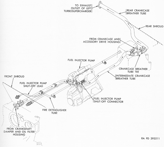
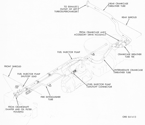
The crankcase breather and fire extinguisher system is sketched here. The crankcase breather system was completely enclosed, allowing the engine to be submerged without the entrance of water and also permitting the crankcase to be vented. This venting was through the left turbosupercharger exhaust outlet. The fire extinguisher tube traveled through the cylinder block "V," and had small holes drilled along its length to expel CO2 from the fixed fire extinguisher system to predetermined directions around the cylinders, fuel injector pump, and intercylinder components. This style of crankcase breather tubing was used on engines with serial numbers 101 through 1185. (Picture from TM 9-2815-200-34.)
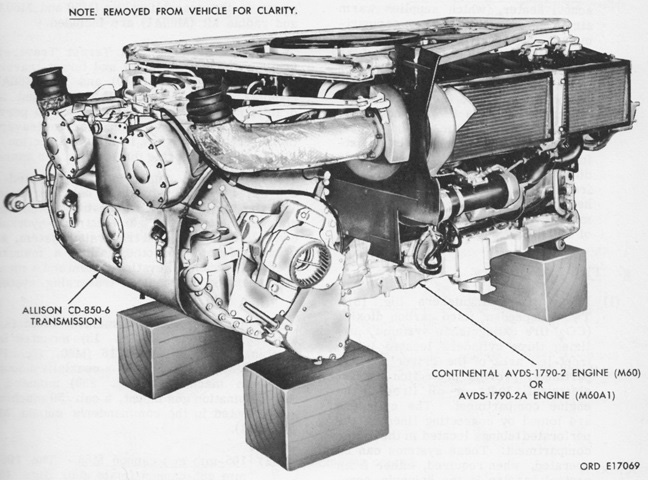
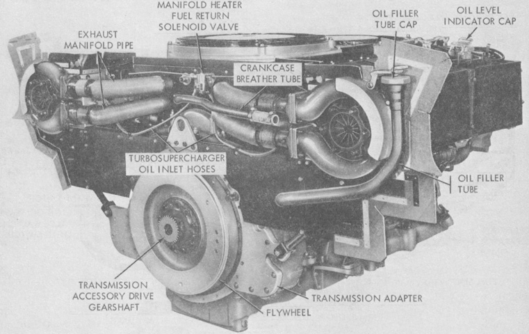
The assembled engine and transmission are shown dismounted from the vehicle. The engine was governed to 2,400rpm. (Picture from TM 9-2350-215-10.)
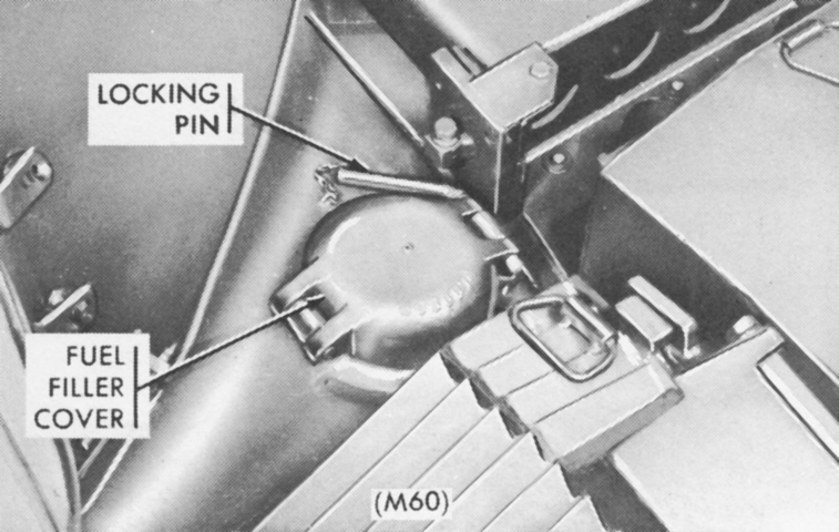
In contrast to the M48A2, which had a fuel filler on each side of the hull for the fuel tanks on their respective sides, the M60 used a single fuel filler at the right front corner of the engine deck. This was used to fill both fuel tanks, or only the right-side tank after the left fuel tank had been isolated. (Picture from TM 9-2350-215-10.)
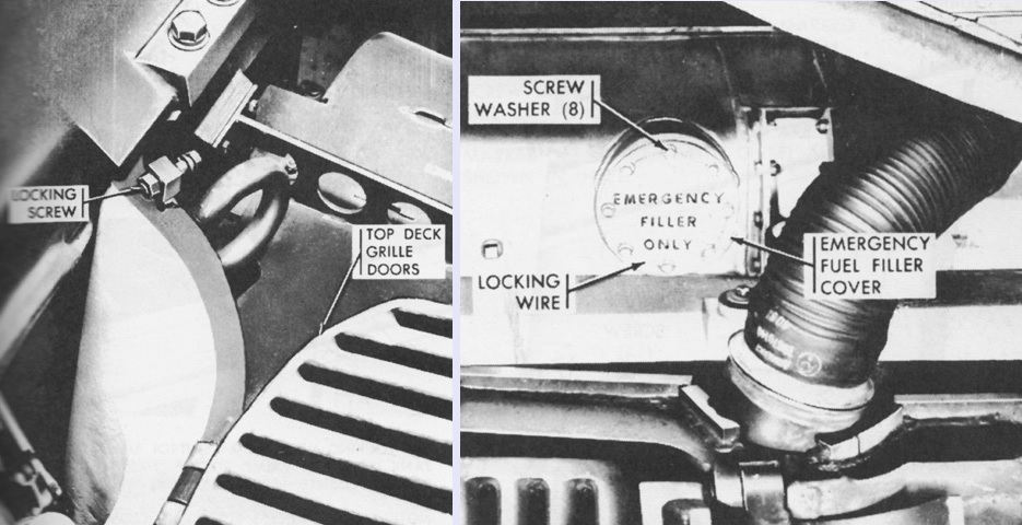
An emergency fuel filler was present on the opposite side of the hull, however. To access this filler, it was necessary to first loosen the locking screw and open the left top grille doors, as shown on the left. The emergency filler was secured by eight screws and washers and locking wire, all of which needed to be removed before the cover could be opened. The emergency filler could fill tanks on both sides, or only the left-side tank after the right tank had been isolated. When finished, the emergency filler cover was again to be secured with the screws, washers, and lock wire. (Picture from TM 9-2350-215-10.)
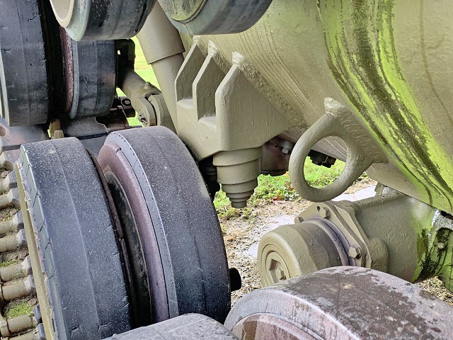
The dual volute spring bump stop for the front road wheel station is highlighted in this image.
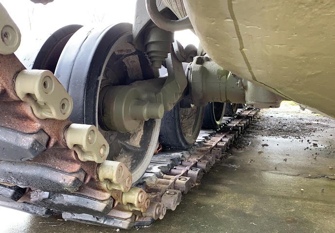
The rear road wheel, its bump stop, and the attachment of the rear shock absorber can be seen here.
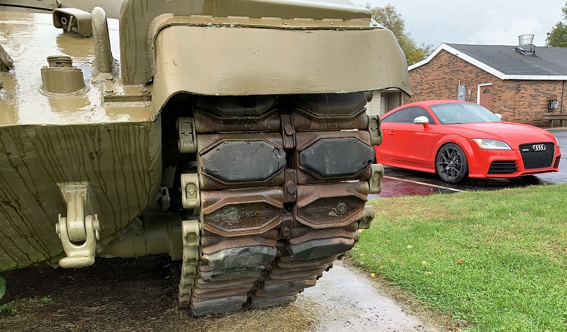
This tank wears the later T142 track with replaceable rubber pads, and some of the pads are missing, allowing a view into their cups. The headlights are also gone on this machine, as is one of the external handles for fire extinguisher activation, located under the guard behind the lifting eye. Details of the fender and mud guard attachment can also be gleaned.
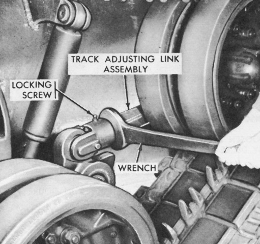
The method of adjusting the track tension is shown here. After the locking screw was loosened, the track adjusting link assembly was turned to move the idler wheel forward or backward to achieve the recommended tension. (Picture from TM 9-2350-215-10.)
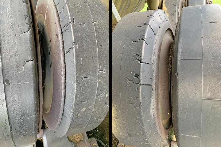
This image shows one difference between the aluminum road wheels (left) and the steel road wheels (right). The track center guides would wear the aluminum wheels at a much faster rate, and these therefore sported a steel ring to be affixed to their inner faces.
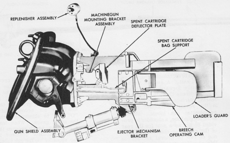
The left side of the combination gun mount M116 is illustrated here. The M116 weighed 5,752lb (2,609kg) and used a concentric hydrospring recoil mechanism with a 5.5 gallon (21L) capacity. The 105mm gun M68 weighed 2,485lb (1,127kg), with the tube comprising 1,660lb (753.0kg) of that. (Picture from TM 9-2350-215-10.)
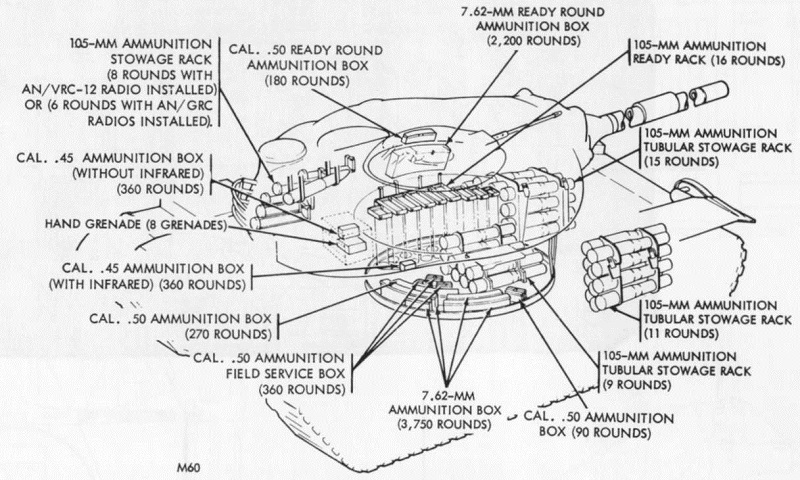
Ammunition stowage in early M60s is drawn here. In later tanks with a smaller AN/VRC series radio in place of the earlier AN/GRC series, eight rounds were stowed in the turret bustle. (Picture from Tank Data, vol. 3.)
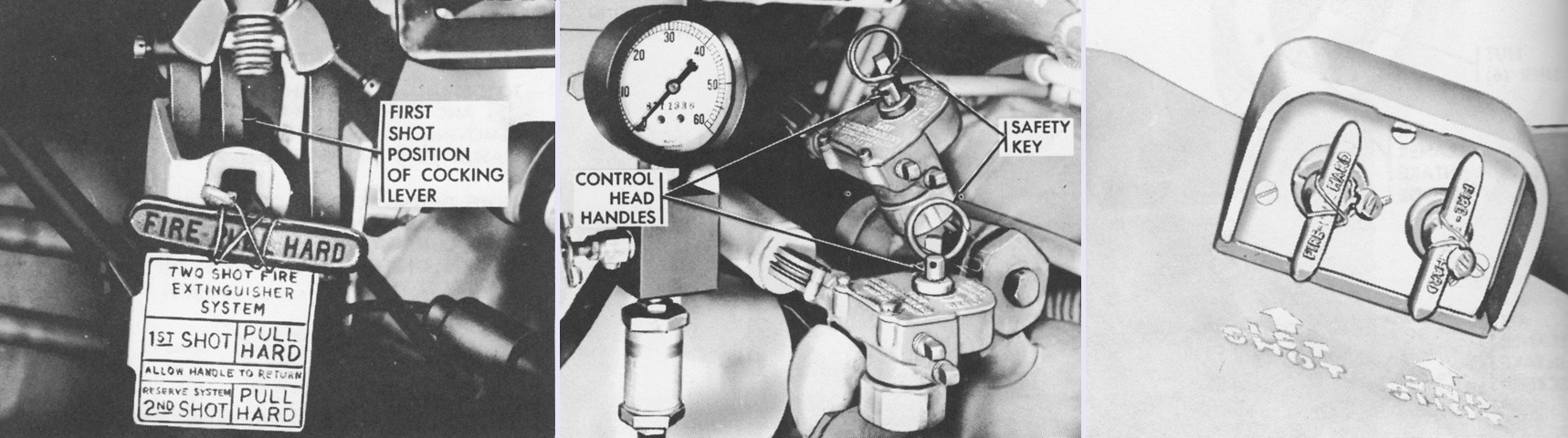
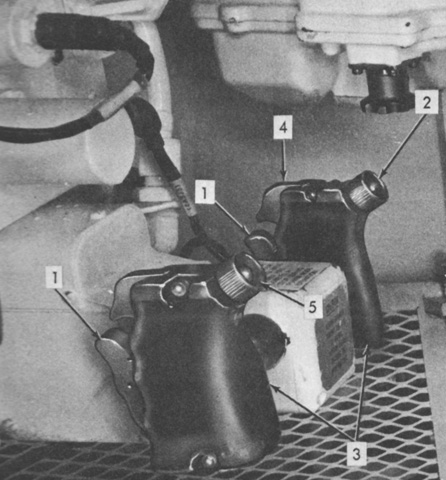
Two independent fixed CO2 fire extinguisher systems provided protection against electrical, fuel, or oil fires in the engine compartment. Three cylinders were mounted to the driver's front left, and could be actuated by handles inside the driver's compartment or outside on the upper hull front. The driver's control handle (left) could be pulled to fire the first shot, then reset and pulled again after about 20 seconds for the second actuation. When the first shot was fired, a switch automatically cut fuel to the engine. If the handle malfunctioned, the safety keys could be removed from the cylinder control heads, and the emergency control head handles (center) could then be pulled all the way to the left to actuate the extinguishers. The external controls (right) featured separate handles for each shot. The emergency handles did not cut fuel to the engine. (Picture from TM 9-2350-215-10.)
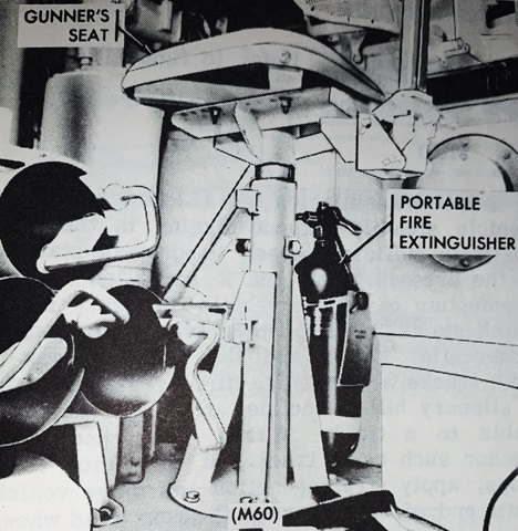
A portable CO2 fire extinguisher was kept under the gunner's seat. (Picture from TM 9-2350-215-10.)
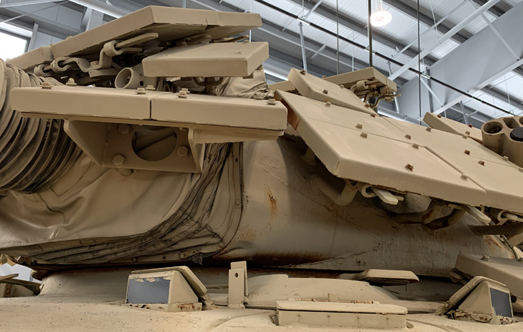
The longer and wider nature of the M60A1's turret is easily seen from above. (Picture from TM 9-2350-215-10.)
The side contour of the turret was also modified, which can especially be seen under the commander's cupola. (Picture from TM 9-2350-215-10.)
Note the enlarged turret stowage basket and the relocation of the searchlight stowage bracket to the right side of the turret rear. (Picture from TM 9-2350-215-10.)
The traverse and elevation system can be contrasted to the initial version above. (Picture from TM 9-2350-215-10.)
The combination gun mount M140 can be seen here removed from the tank. (Picture from TM 9-2350-215-10.)
The commander's position in the new turret is illustrated here. (Picture from TM 9-2350-215-10.)
The gunner's station is seen in this picture from the opposite side of the 105mm gun. (Picture from TM 9-2350-215-10.)
The front of the gunner's position in the new turret is labeled. (Picture from TM 9-2350-215-10.)
The ballistic computer M13A2 is detailed in this picture. (Picture from TM 9-2350-215-10.)
The turret rear is seen here; note that the gun is in the travel lock to the rear, and consequently the driver's position is visible below the turret ring. The turret bustle was occupied by radio racks, the ventilator, and ammunition stowage. On the left of the image across from the loader's seat is the commander's seat, and the commander's observation seat can be seen at the top left in the stowed position. (Picture from TM 9-2350-215-10.)
Fixtures on the left side of the turret are labeled in this image. The rangefinder exits the turret side just forward and below the loader's hatch. (Picture from TM 9-2350-215-10.)
The loader's side of the 105mm gun is seen here. (Picture from TM 9-2350-215-10.)
The driver's steering control was changed from a conventional-type steering wheel to a T-bar. A right turn was accomplished by pulling the right handgrip to the rear, and vice-versa. When driving with the hatch open, it was no longer necessary to remove the center M27 periscope as it could be lowered into a dropped position. (Picture from TM 9-2350-215-10.)
The driver's position's right side is seen here. (Picture from TM 9-2350-215-10.)
This image shows the left side of the driver's compartment. (Picture from TM 9-2350-215-10.)
The revised master control panel is detailed in this image. (Picture from TM 9-2350-215-10.)
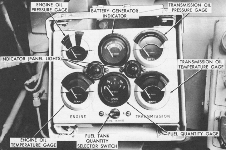
The gage indicator panel was redesigned and mounted ahead of the master control panel instead of above. Most of the numbers on the gage faces were overlaid with green or red arcs indicating normal or abnormal readings. (Picture from TM 9-2350-215-10.)
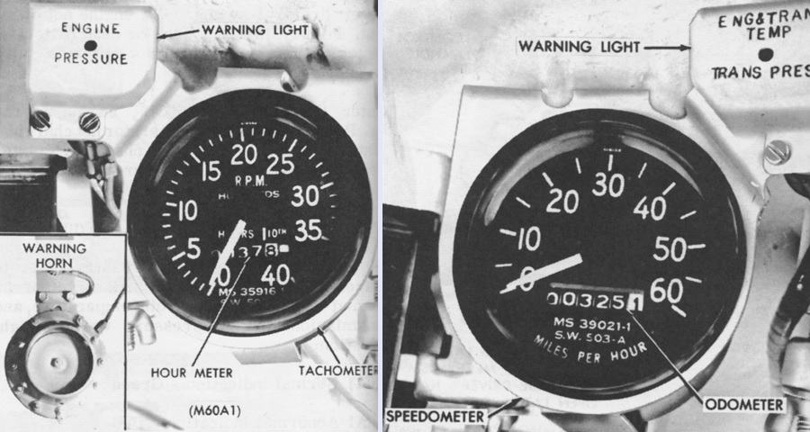
The low engine oil pressure warning light near the tachometer/odometer was reinforced by a warning horn that sounded whenever the light was illuminated. (Picture from TM 9-2350-215-10.)
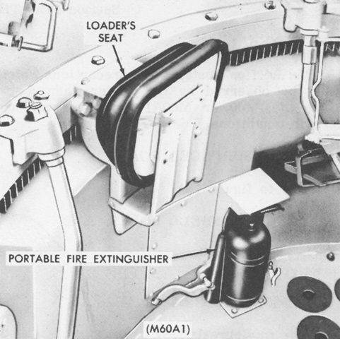
The portable fire extinguisher was moved to the opposite side of the turret, under the loader's seat. (Picture from TM 9-2350-215-10.)
The AVDS-1790-2A was externally similar to the AVDS-1790-2, but incorporated smoke reduction features that resulted in the production of less exhaust smoke. These features included a change to the fuel injection metering pump metering mechanism that reduced fuel flow at engine speeds of under 1,600rpm, and the use of a new pump with additional product improved features; reduction of the fuel injector atomizer nozzle spray holes from 0.300mm to 0.275mm diameter to enhance atomization and provide better combustion; turbosuperchargers with new nozzle rings that provided the proper manifold air flow for combustion with the new injection pump and injector nozzles; and an advance in the fuel injector metering pump timing from 26° BTC to 30° BTC as a result of these changes. The timing mark on the flywheel was duly relocated. The late-model crankcase breather and fire extinguisher system is drawn here, and was found on engines with serial numbers 1186 and above. (Picture from TM 9-2815-200-34.)
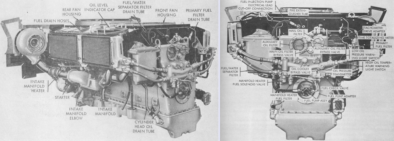
Two views of a later-production AVDS-1790-2A are above. Further changes included the supersession of the conventional dual replacement element secondary fuel filter with a fuel/water separator unit; oil temperature and pressure transmitters and switches were moved to the engine front to ease maintenance; the fuel injection pump drive coupling could be optionally splined or a diaphragm type; the fuel injector nozzle fuel return lines were changed from rigid steel tubes to flexible hoses to improve service life; a double lip oil seal in the cooling fan drive prevented water from entering the engine during deep-water fording; an improved fuel injection pump was used with a filter at the fuel inlet; the cooling fan clutch was simplified by eliminating the hydraulic engagement feature; the oil filler tube was moved to behind the left turbosupercharger, which prevented spillage from clogging the cylinder cooling fins and transmission oil coolers and also eliminated the need for the filler and indicator tube splash pan drain; a high-capacity replaceable element was used for the primary fuel filter instead of the previous screen-type element; cylinder wall thickness was increased; fuel filter drain cocks and hoses were replaced by rigid lines, with the drain valves moved to the top of the engine; additional clamps and supports were added for the fuel injection lines, as well as increased support and relocation of other lines to prevent chafing and vibration failures; preformed packing was added to the starter bearing cage, as well as a flat gasket to the drive adapter to prevent oil leaks; and a time totalizing meter was added to record engine operating hours. (Picture from TM 9-2815-200-35.)
The relocated oil filler tube on late AVDS-1790-2A engines is visible in this rear view. (Picture from TM 9-2815-200-35.)
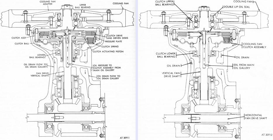
The early hydraulically-actuated fan clutch on the left can be contrasted to the simplified mechanical version on the right. (Picture from TM 9-2815-200-35.)
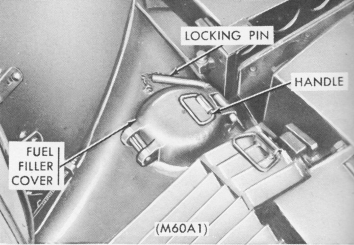
A handle was added to the M60A1's fuel filler cover. (Picture from TM 9-2350-215-10.)
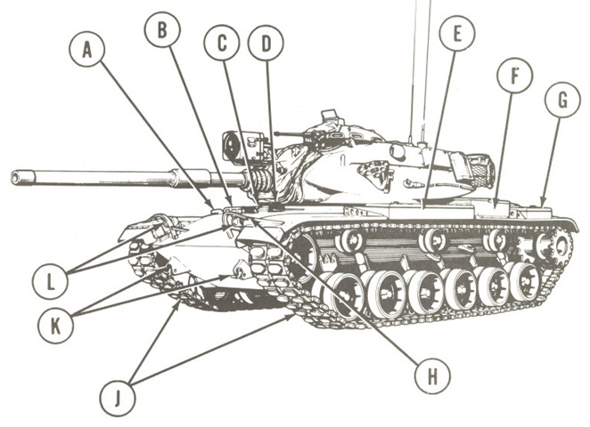
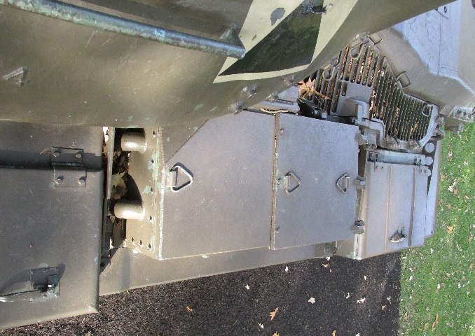
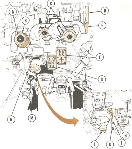
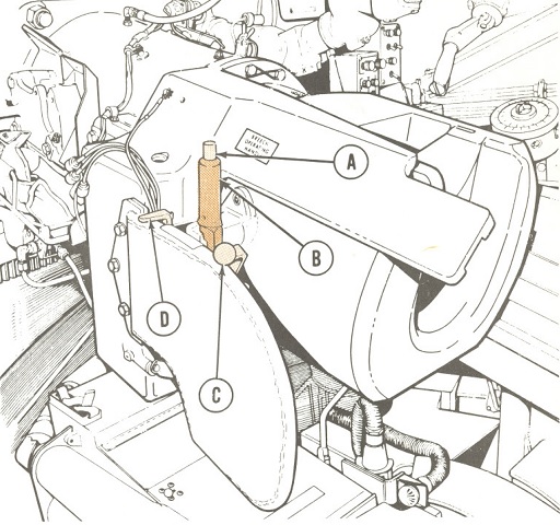
Features found on the RISE tank are labeled here. A. Personnel heater exhaust. B. Driver's vision blocks. C. Driver's hatch. D. Driver's periscope cover. E. Fender stowage box. F. Engine air cleaner. G. Rear fender stowage box. H. Fire extinguisher release handles. J. Track. K. Tow hooks. L. Headlights. (Picture from TM 9-2350-257-10-1.)
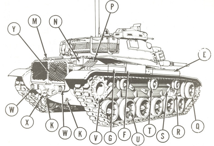
E. Fender stowage box. F. Engine air cleaner. G. Rear fender stowage box. K. Tow hooks. M. Main gun travel lock. N. External interphone box. P. Engine access grille covers. Q. Compensating idler wheel. R. Compensating idler wheel adjusting link. S. Shock absorber. T. Track support roller. U. Roadwheel and hub. V. Drive sprocket. W. Taillights. X. Tow pintle. Y. Transmission access grille doors. (Picture from TM 9-2350-257-10-1.)
A. 105-mm gun tube. B. Bore evacuator. C. Gunner's telescope port. D. Gunshield cover. E. Caliber .50 machine gun barrel. F. Smoke grenade launchers. G. Gunner's periscope. H. Machine gun interrupter. J. Commander's periscope. K. Commander's hatch. L. Smoke grenade stowage boxes. M. M19 commander's cupola. N. Cupola vision blocks. P. Turret ventilating blower cover. Q. Bustle rack, stowage. R. Antenna mounts. S. 5-gallon [20L] can stowage. T. Loader's hatch. U. Loader's periscope cover. V. Rangefinder blister. W. Searchlight power receptacle. X. Searchlight bracket. Y. 7.62-mm machine gun port. Z. Searchlight. (Picture from TM 9-2350-257-10-1.)
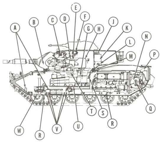
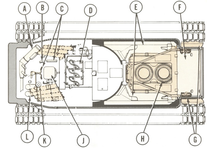
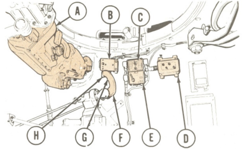
The tank's internal arrangement can be seen in this sketch. A. Headlight stowage brackets. B. 105-mm gun mount. C. Replenisher assembly. D. Breech operating handle. E. Loader's guard. F. Rangefinder. G. Commander's platform. H. Gunner's guard. J. Observation seat (stowed). K. Radio equipment. L. Oddment tray. M. Inflatable hull-to-turret seal. N. Transmission. P. Engine exhaust elbows. Q. Universal joint. R. Hull drain valves. S. Engine air cleaner intakes. T. Gunner's seat. U. Turret platform. V. Torsion bars (total of 12). W. Driver's escape hatch. (Picture from TM 9-2350-257-10-1.)
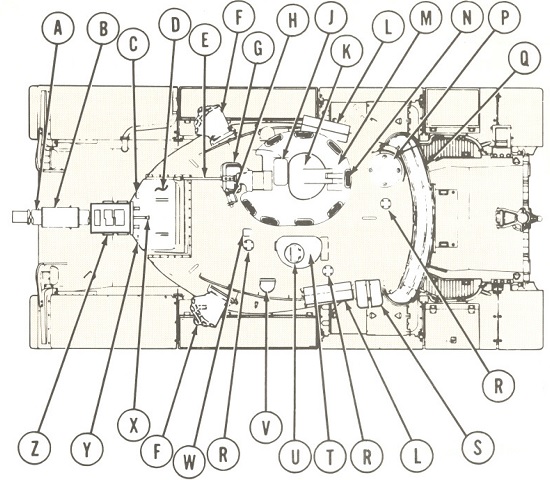
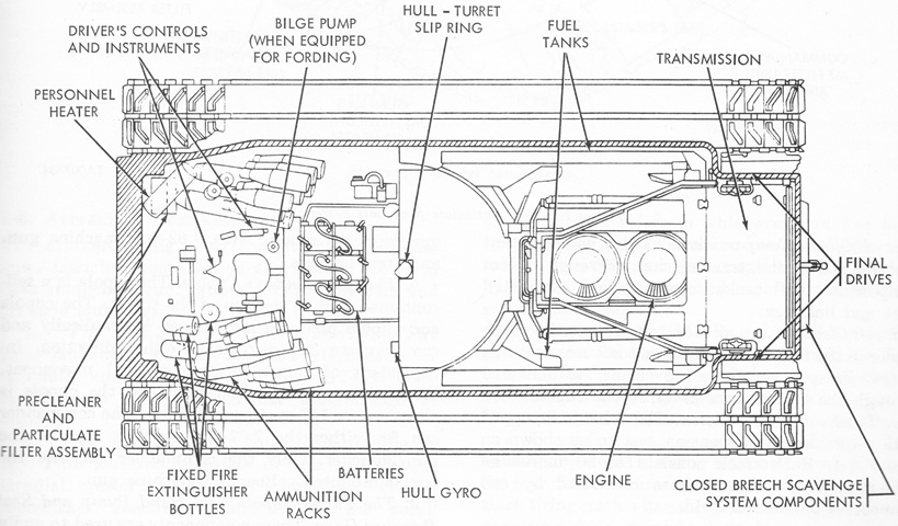
The hull's internal components are drawn from above. A. Personnel heater. B. Driver's instruments. C. Driver's controls. D. Batteries. E. Fuel tanks. F. Transmission shroud. G. Final drives. H. Engine. J. Driver's seat. K. Fire extinguisher release handle. L. Fixed fire extinguishers. (Picture from TM 9-2350-257-10-1.)
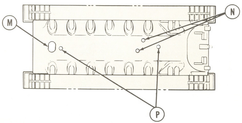
The underside of the hull is represented here. M. Driver's escape hatch. N. Fuel tank drain plug access cover. P. Hull drain valves. (Picture from TM 9-2350-257-10-1.)
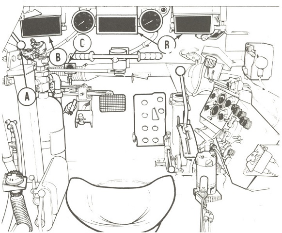
The driver's controls are labeled in the following series of illustrations. A. Driver hatch control. B. M27 periscope. C. Brake pressure gage. (Picture from TM 9-2350-257-10-1.)
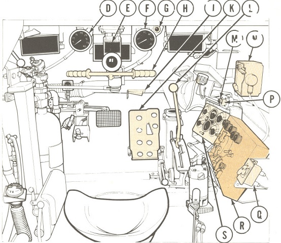
D. Tachometer/Hour meter. E. AN/VVS-2 night vision viewer (RISE PASSIVE tanks) or IR periscope M24 (RISE tanks). F. Speedometer/odometer. G. Powerplant warning lamp [lights if engine oil pressure, engine oil temperature, or transmission oil temperature is in red area]. H. Steering control. J. Heater air outlet door. K. Accelerator pedal. L. Transmission shift control. M. Smoke generator indicator light. N. Intercom control panel. P. Smoke generator switch. Q. Air cleaner blower switch. R. Master control panel. S. Indicator panel. (Picture from TM 9-2350-257-10-1.)

T. Manifold heater switch (on end of purge pump handle) [Turns fuel to manifold heaters on and off. Turns power to manifold heater spark plugs on and off.]. U. Purge pump handle. V. Accelerator lock lever [locks accelerator pedal in preset position]. W. Forward drain valve control lever. X. Rear drain valve control lever. Y. Gas particulate air heater switch and indicator (located at rear of driver's seat). Z. Escape hatch lever. AA. Driver seat control levers (4). AB. Brake pedal. AC. Headlight dimmer switch. AD. Turret seal pump. AE. Manual fuel shutoff handle and latch. (Picture from TM 9-2350-257-10-1.)
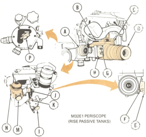
The gunner's position is the subject of the following series. A. Telescope M105D. B. Diopter ring. C. M32 periscope (RISE tanks). D. Ballistic shield operating handle. E. Ballistic shield lock plunger. F. Gunner's switch box. G. Stabilization control selector. H. Deflection knob. J. Deflection lock. K. Elevation lock. L. Elevation knob. M. Light source control. N. Reticle selector. (Picture from TM 9-2350-257-10-1.)
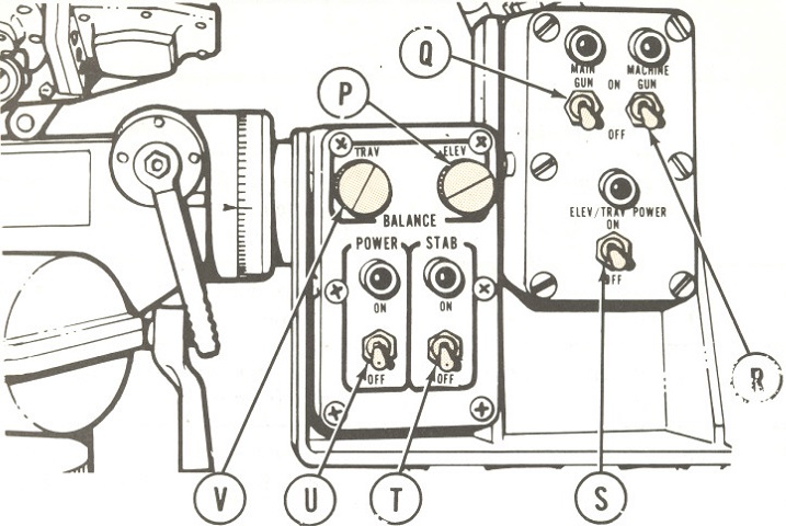
P. Elev Balance knob [eliminates main gun stabilization elevation drift]. Q. Main gun switch. R. Machine gun switch. S. Elev/Trav power switch. T. Stab switch [turns on stabilization system from standby]. U. Power switch [places stabilization system in standby mode when on]. V. Trav balance knob [eliminates turret stabilization traversing drift]. (Picture from TM 9-2350-257-10-1.)
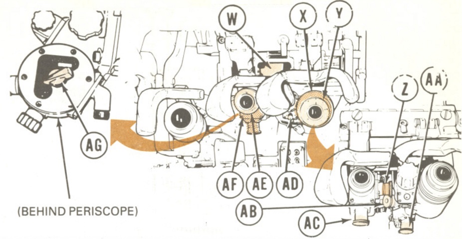
W. Unity power window. X. IR body. Y. M32 IR body diopter ring. Z. Daylight body deflection knob. AA. IR body elevation knob. AB. IR body deflection knob. AC. Daylight body elevation knob. AD. IR switch [selects vehicle power or battery for IR body]. AE. Daylight body diopter ring. AF. Daylight body. AG. Source control knob [adjusts daylight body and infinity sight reticle brightness]. (Picture from TM 9-2350-257-10-1.)
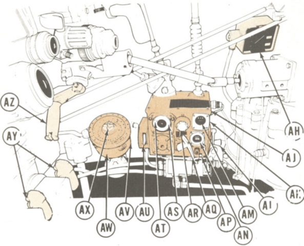
AH. Interphone control box. AJ. M13A2 ballistic computer. AK. Rheostat knob. AL. Superelevation handcrank. AM. Superelev mil counter. AN. Ammo indicator. AP. Reset pushbutton switch. AQ. Ammo selector handle. AR. Range correction knob. AS. Outer (superelevation) pointer. AT. Inner (range) pointer. AU. On/off circuit breaker. AV. Rheostat knob. AW. M28E2 azimuth indicator. AX. Resetter knob. AY. Firing buttons. AZ. Manual traversing handle. (Picture from TM 9-2350-257-10-1.)
A. M13A3 elevation quadrant. B. Elevation scale. C. Rheostat. D. Level vial tube. E. Manual firing handle. F. Firing button. G. Manual elevating handle. H. Gunner's control handles. J. Magnetic brake palm switch. K. Gas particulate air heater switch. L. Micrometer scale. (Picture from TM 9-2350-257-10-1.)
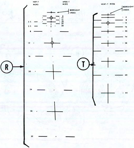
The gunner could switch between two sighting reticles on the telescope M105D. Reticle R featured M393 HEP-T from 350m to 3,200m on the left and M392 APDS-T from 400m to 2,800m on the right, while reticle T was used with M456 HEAT-T from 400m to 4,400m. When using APERS-T ammunition, a data plate was used to convert the range for HEAT-T to the appropriate range for APERS-T. (Picture from TM 9-2350-257-10-1.)
The passive night vision instruments are shown here. A. Daylight body diopter ring. B. Unity power window. C. Passive body (RISE PASSIVE tanks). D. Passive body diopter ring. E. Shutter lever. F. Power switch. G. Reticle control. H. Tube control [controls passive body image intensification]. J. Daylight body deflection knob. K. Passive body deflection knob. L. Passive body elevation knob. M. Daylight body elevation knob. N. Daylight body. P. Light source control. (Picture from TM 9-2350-257-10-1.)
The tank commander's station is detailed in the following images. A. M17A1 rangefinder. B. Cupola electrical power control switch. C. Control box [for remote radio frequency selection]. D. Searchlight remote. E. Interphone control box. F. Commander's control handle. G. Palm switch. H. Firing switch. (Picture from TM 9-2350-257-10-1.)
J. Grenade launcher switch. K. Power switch [for smoke grenade launcher system]. L. Power light. M. Emergency stab shutoff switch. N. Domelight. P. Blower switch [for ventilator blower]. Q. Stabilization power indicator. (Picture from TM 9-2350-257-10-1.)
R. Gas particulate air heater switch. S. Searchlight control. T. Receiver-transmitter RT 246/VRC [only in some vehicles]. U. Battle override switch [restores communications power if circuit breaker opens during battle]. V. Audio frequency amplifier AM 1780/VRC. W. Receiver R-442/VRC [not on all vehicles]. (Picture from TM 9-2350-257-10-1.)
A. Elevation handle [for manual elevation of caliber .50 machine gun]. B. Machine gun trigger switch. C. Caliber .50 machine gun access door. (Picture from TM 9-2350-257-10-1.)
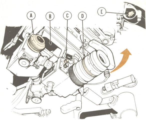
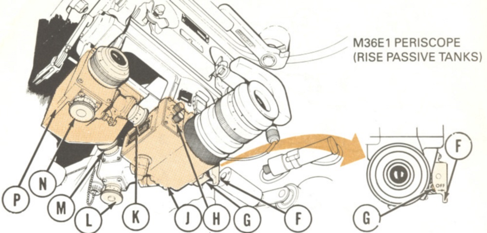
D. Headrest adjust lever. E. M36 periscope (RISE tanks). F. unity power window. G. Light source control. H. Caliber .50 machine gun electrical safety switch. J. Cupola traverse control handle. K. IR body diopter ring. L. Ballistic shield control handle. M. IR body. N. IR switch [to select vehicle or battery power]. P. Elevation knob. Q. IR body and daylight body deflection knobs. R. Daylight body elevation knob. S. Daylight body diopter ring. T. Daylight body. U. Azimuth lock and interlock. (Picture from TM 9-2350-257-10-1.)
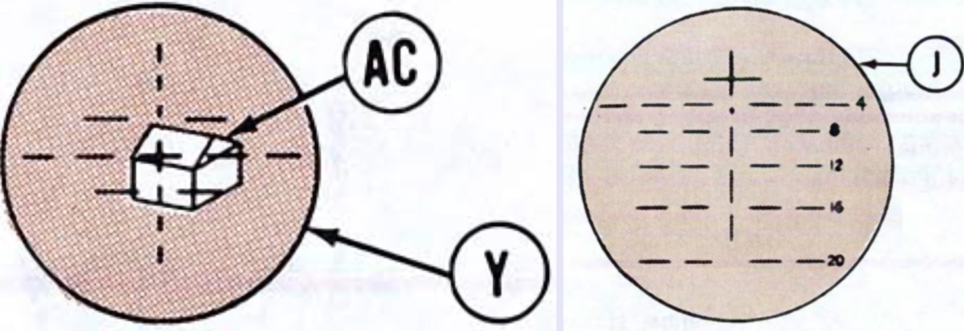
The reticles for the infrared and daylight bodies of the periscope M36 are drawn on the left and right, respectively. Both provided 8x magnification. On the left, (AC) denotes the target and (Y) is the background grain that should appear clear once the diopter was properly adjusted. On the right, (J) is the reticle. (Picture from TM 9-2350-257-10-2.)
A tank with passive night vision is the subject of this and the following images. A. Daylight body diopter. B. Unity power window. C. Passive body reticle control. D. Passive body diopter ring. E. Light source control. (Picture from TM 9-2350-257-10-1.)
F. Shutter lever [opens shutter and depresses power switch when moved down]. G. Passive body power switch. H. Tube control [controls passive body image amplification]. J. Passive body. K. Daylight body deflection knob. L. Passive body elevation knob. M. Passive body deflection knob. N. Daylight body elevation knob. P. Daylight body. (Picture from TM 9-2350-257-10-1.)
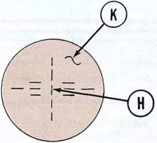
The reticle for the periscope M36E1's passive body is sketched above. (H) is the reticle and (K) is the background grain. The daylight body was the same as the periscope M36. (Picture from TM 9-2350-257-10-2.)
The breech of the 105mm gun is shown in this picture. The gun's normal recoil length was 12" (30cm) with a maximum of 13.5" (34.3cm), and the estimated gun tube life was 400 equivalent full charge rounds. A. Plunger. B. Breech operating handle. C. Main gun safety switch. D. Trip lever [allows safety switch to move from fire to safe]. (Picture from TM 9-2350-257-10-1.)
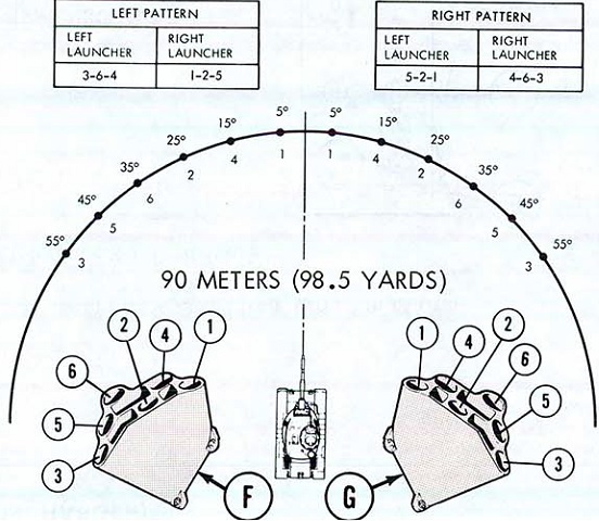
The dispersion of the smoke grenade launchers is sketched here. The left and right patterns had their own firing buttons; to discharge all grenades, both buttons needed to be pressed. The smoke coverage was 50m (160') long and greater than 6m (20') high. It would be established in under 5 seconds and last for 60-90 seconds. (Picture from TM 9-2350-257-10-2.)
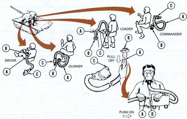
The crew were provided with M25A1 masks that could be attached to hoses that connected to the tank's gas particulate systems. The systems filtered chemical and biological agents, but would not protect from carbon monoxide. Due to the chance of frostbite, the filter heater was to be operating for 15-20 minutes before the masks were connected when the tank was in arctic conditions. A. Hose. B. Connector. C. M3 heater unit. D. M25A1 tank mask cannister [sic]. (Picture from TM 9-2350-257-10-2.)
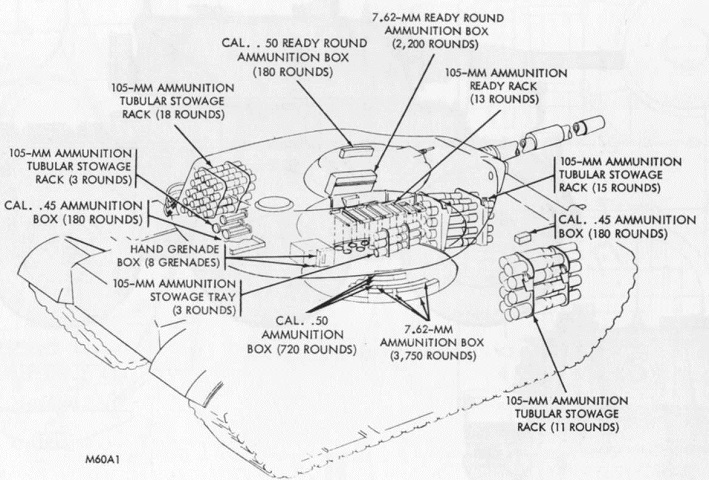
Ammunition stowage in late M60A1s is drawn here. Earlier tanks had a three-round stowage tray instead of the three-round tubular stowage rack. (Picture from Tank Data, vol. 3.)
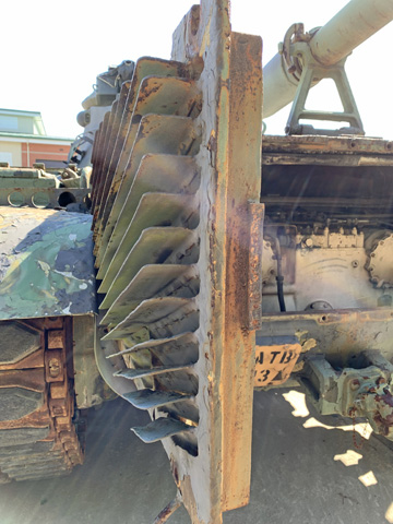
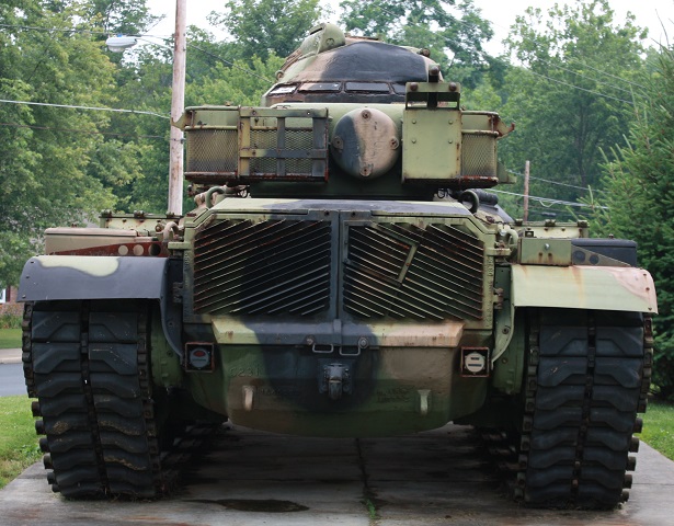
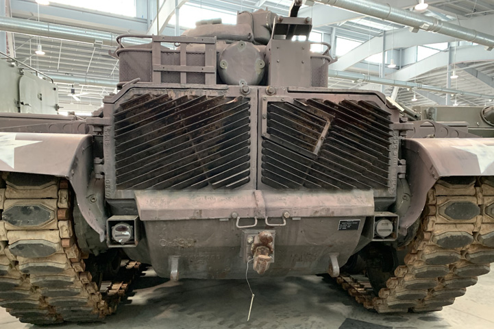
With the rear engine access doors open, the thickness of the louvres can be seen.
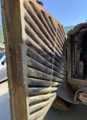
The louvre design allowed for the passage of air and exhaust fumes, but projectiles or fragments would not find a direct path into the engine compartment.
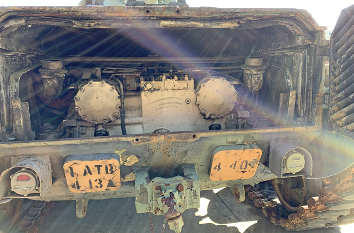
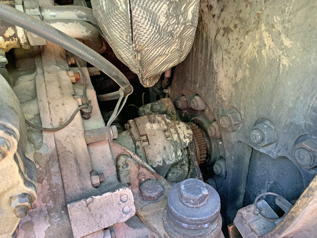
Peering into the engine compartment, the white-painted transmission blocks much of the engine from view. The large circular covers on the transmission were for the reverse range servo piston on the left and the low range servo piston on the right. The engine's two exhaust tubes are outboard of these servo piston covers, although the 90° elbows that typically direct the exhaust to the rear are absent.
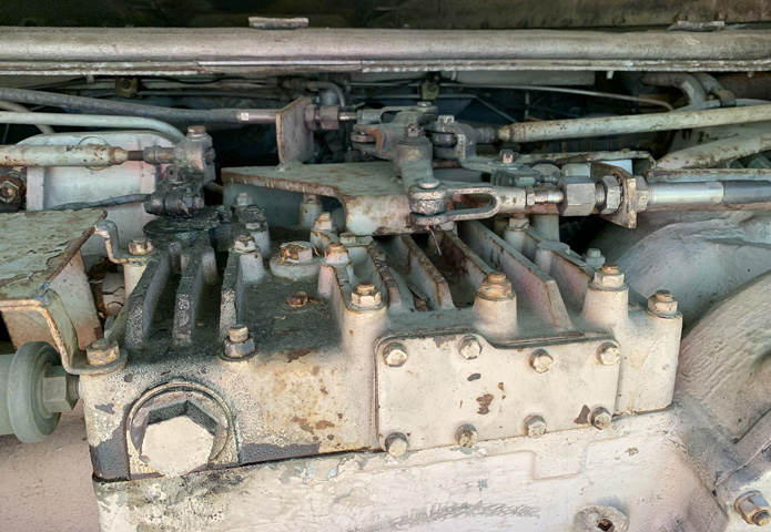
The linkages and rods attaching to the transmission control valve body assembly are highlighted in this image.
The transmission connected to the final drives via universal joints and final drive adapter assemblies.
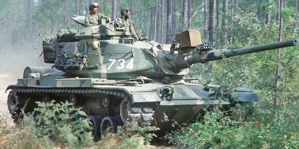
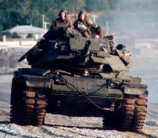
This vehicle is also fitted with the aluminum wheels, but note the horizontal hull tiedown eyes compared with vertical hull tiedown eyes the above vehicle. M60 and M60A1 hulls up to serial number 5025 had three vertical tiedown eyes rated at 20,000lb (9,000kg) each. M60A1s from serial number 5026 and 152mm gun-launcher tanks M60A2 from serial number 4426 had four horizontal tiedown eyes rated at 490,000lb (220,000kg) side load and 413,000lb (187,000kg) oblique load. Late-production hulls were fitted with only two horizontal lifting eyes, as the middle two were deleted. This tank is equipped with the 1kw AN/VSS-3A xenon infrared searchlight, which is plugged into the receptacle on the turret roof. The light had a peak candlepower output of 50 million, and could operate with a compact beam of 1° minimum or a spread beam of from 1° to 7°. In front of this on the gun tube is a pyrotechnic device to simulate the firing of the main gun. The right-hand blister for the coincidence rangefinder is visible near the top of the turret just below the commander's cupola. Armored top-loading air cleaners are also visible on the rear fenders between the stowage boxes. This tank belonged to the 24th Infantry Division, and was taking part in Exercise GALLANT EAGLE '79 at Eglin Air Force Base. (Picture taken 25 Oct 1978 by SSGT Dwight A. Jackson; available from the Defense Visual Information Center.)
A closer view of the AN/VSS-3A and its mount is provided here, although the power cable is not present.
The AN/VVS-2 night vision viewer has been installed in the driver's hatch. The forward periscope M27 was lowered onto a support bracket so as not to block the forward view.
The loader's hatch and commander's cupola are open on this machine, allowing a glance at the roof armor thickness. The empty mount for the AN/VSS-3A searchlight is present above the gun tube. An armored top-loading air cleaner can be seen on the fender. The tanks belonged to A Troop, 3d Squadron, 4th Cavalry, 25th Infantry Division. (Picture taken 10 Sep 1983 by Al Chang; available from the National Archives.)
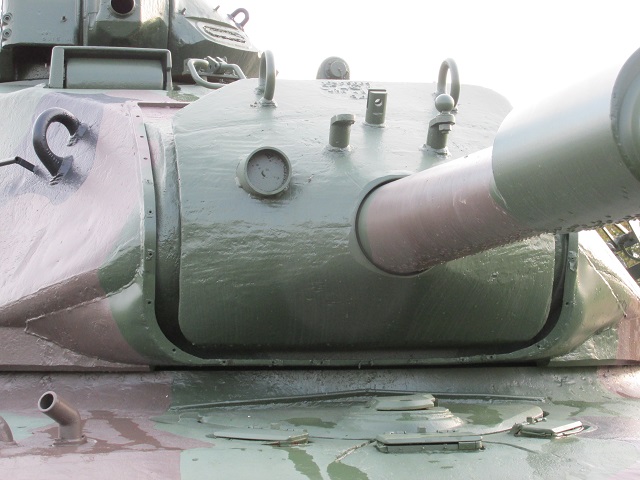
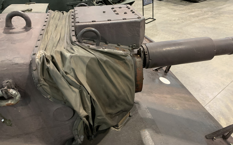
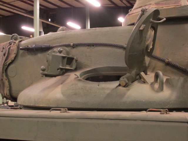
A view of the turret front without the canvas dust cover is provided here. The aperture in the gun shield for the gunner's telescope M105C has been blanked off. The three attachment points for the searchlight can be seen above the gun tube, and its capped power receptacle on the turret roof is visible. The small pipe to the driver's right on the hull roof is the bilge pump outlet.
The gun shield is shown in profile in this image. The coaxial machine gun aperture is on this side of the vehicle.
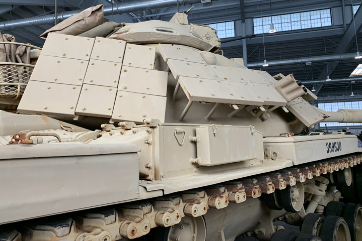
This Marine tank is fitted with explosive reactive armor (ERA). These tiles are composed of explosive sandwiched between two steel plates. When struck by a high-explosive antitank (HEAT) shell or missile, the HEAT penetrator detonates the explosive, sending the plates in opposite directions. This action destabilizes the HEAT penetrator, making it less effective at penetrating the tank's armor. This tank was participating in the US/Thai exercise THALAY THAI '89. (Picture taken 1 Sep 1989; available from the Defense Visual Information Center.)
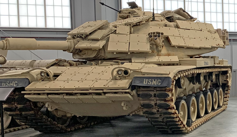
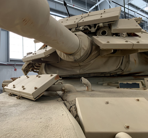
The ERA layout on this machine will be the subject of the next images. Since ERA is more effective if it is angled versus incoming fire, the turret tiles are purposely inclined even where the turret is relatively vertical. Note that clearance was left for vision from the rangefinder.
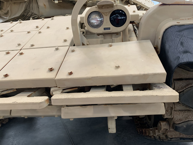
Similarly to the rangefinder on the turret, clearance was left on the hull for the headlight assemblies.
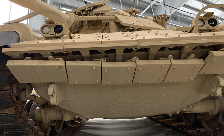
The bottom of the hull front was protected by a single row of tiles.
The turret ring had protection added to the left of the driver's hatch.
On the right side of the hull, however, the ERA tiles were mounted farther out, on the fender outboard of the personnel heater exhaust.
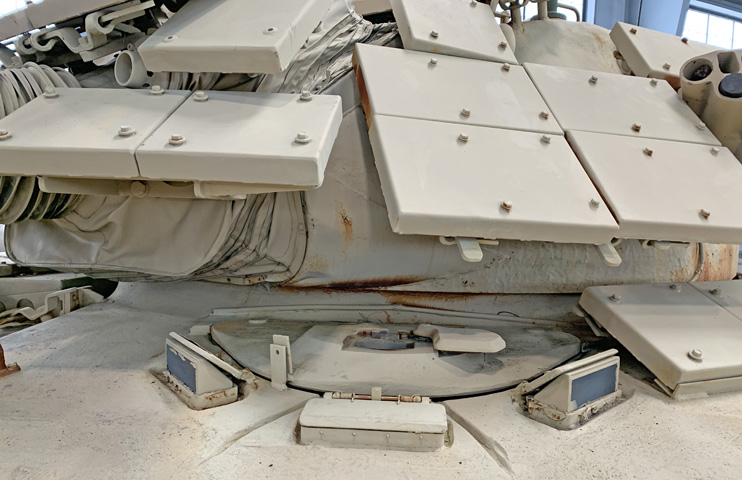
The cover for mounting the driver's AN/VVS-2 passive viewer in the driver's hatch is open on this machine. Pushing the ERA tiles on the right hull roof out to the fender as illustrated above left clearance for the driver's hatch to swing open to the right.
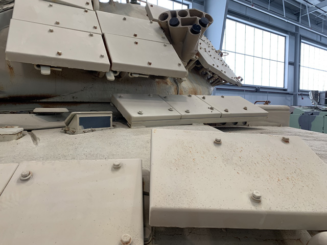
The angling of the ERA tiles can be seen in this image, with the lower supports longer than the upper supports. Clearance for the rangefinder and smoke grenade launcher was accounted for. Note the different sizes of ERA tiles used.
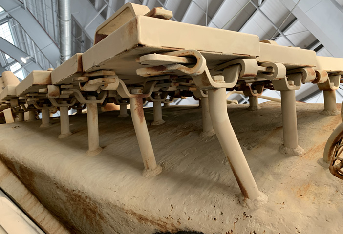
Looking upwards at the ERA on the turret's left rear side, the longer lower supports are obvious. The turret stowage basket can just be seen at the right edge of the image.
The ERA mounted to the gun shield presented a steeper angle; this would presumably retain a decent angle from vertical if, for example, the gun was depressed with the tank in a reverse slope position. The coaxial machine gun aperture can be seen peeking through the three ERA mounts visible at the turret front.
The opposite side of the gun shield presents a similar layout, with the gunner's telescope unobstructed by the ERA mounts.
The turret shape changed again with the M60A2, with a compact turret mounting a 152mm gun-launcher replacing the 105mm gun turret. The gunner and loader had their own hatches on either side of the turret base, and the commander was stationed in a cupola at the turret rear. The turret was 153" (389cm) long, 100" (250cm) wide, 36" (91cm) high, and weighed 32,406lb (14,699kg) combat loaded. The cupola was 55" (140cm) in diameter, 22" (56cm) tall, and weighed 5,180lb (2,350kg) combat loaded. (Picture from TM 9-2350-232-34.)
A cross-section of the turret is sketched here. Contrary to most American tanks, the commander was situated directly behind the ordnance. (Picture from TM 9-2350-232-10 C3).
The narrow cross-section of the turret can be glimpsed here. The upper part of the turret was not much wider than the gun mount, and the turret widens near the base for the gunner's and loader's stations. The service headlights and infrared headlights are obvious; above these in both headlight groups is a blackout driving light, and below them is a blackout marker light. The mounting locations for the driver's three M27 periscopes are visible in the upper hull, and the exhaust for the personnel heater can be seen running from the right side of the hull roof to the tank's right fender. This vehicle is running on the T142 track with replaceable rubber pads, and a bore evacuator is present on the gun-launcher.
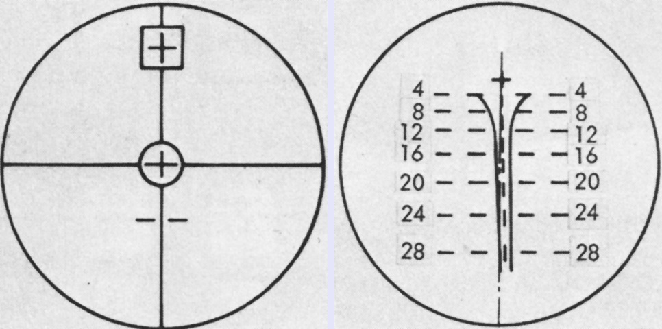
The bore evacuator on the 152mm gun-launcher is apparent, positioned about halfway down the short gun tube. The housing above the gun was for the Shillelagh missile's infrared transmitter. The gunner's M126 telescope is visible, and under the padlocked cover above the telescope is the aperture for the tank's laser rangefinder. The telescope was the sight used for the missile, and the primary sight for canister and coaxial machine gun engagements. It was the secondary sight for HEAT-MP shells after the gunner's M50 periscope. The external triggers for the tank's fire extinguishers are visible under the guard on the hull front slope. The gun-launcher weighed 1,325lb (601.0kg), and its shield assembly 500lb (230kg). The driver's periscopes M27 are visible in the background. These 1x periscopes had a 121° horizontal and 41° vertical field of view. The 1x infrared periscope M24 that could be installed in his hatch had a 509.64 mil field of view and could be pivoted in the hatch 569 mils to the right and left and 266.7 mils in elevation.
Access covers on top of the missile infrared transmitter are visible from above. Lifting rings were present on the front of the turret roof as seen here, and on the sides of the turret behind the gunner's and loader's hatches.
Details of the suspension, such as the aluminum road wheels and friction snubbers on the first two and last road wheels, are visible. A 23" (58cm) 2.2kw 100 million candlepower xenon searchlight is mounted on the turret's left side, in front of the loader's hatch. An infrared filter could be used as well, black on the AN/VSS-1 searchlight and pink on the AN/VSS-2. The light could be used in overdrive mode for 15-20 seconds once every five minutes, which increased its output to 150 million candlepower. The beam width for both the AN/VSS-1 and -2 was either 0.5-0.75° in narrow mode or 7° in wide mode. The beam was 1.2° high in each mode. With white light, the lamp had a planning range of 1,500m (1,640yd); with the pink filter the AN/VSS-2 had an infrared planning range of 1,000m (1,090yd).
M60A2 possessed a new commander's cupola, which is illustrated here. His M51 periscope is mounted at the top of the cupola, and the circular mount for the .50cal machine gun is offset to the right. Both cupola and turret were stabilized in azimuth and elevation. The gunner's M50 periscope is visible on top of his hatch on the turret's low right side. A tow cable is stowed on the side of the turret, and a stowage basket rings the turret rear.
The commander's cupola base was actually wider than the turret roof. The gunner's hatch and periscope guard are visible at the bottom of the image, and the power receptacle for the searchlight faces to the rear on the turret roof.
Antenna mounts are present at the rear of the turret roof, and smoke grenade launchers are welded to the rear sides of the turret, inside the stowage basket.
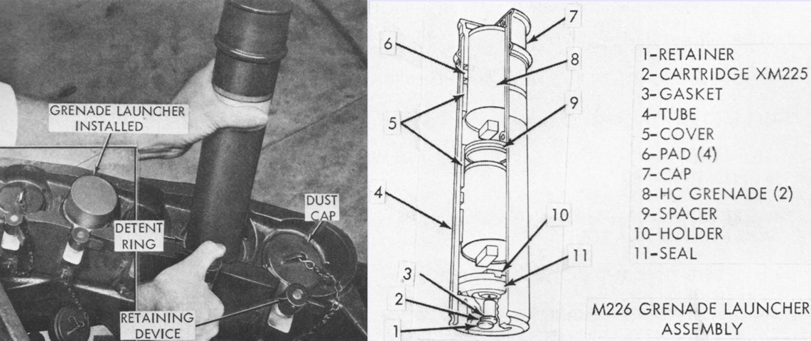
A ballistically-shielded four-tube grenade launcher firing station was found on each side of the turret bustle. An M226 grenade launcher was inserted into each tube, and these could be fired either electrically or by using the blasting machine in the turret. The M226 grenade launcher was a plastic cylinder containing an M225 cartridge and two AN-M8 HC-filled smoke grenades secured by a two-piece sabot (Cover 5 and Holder 10 in the image above). Upon firing, the firing pin would strike the M225 cartridge percussion primer, thereby igniting the propellant in the M225. The grenades in their sabot were then ejected through the end of the cap to a range of 31-46m (100-150'). The M226 was 38.10cm (15.00") long, 9.37cm (3.69") in diameter, and weighed 2.315kg (5.104lb). The AN-M8 HC grenade was 6.35cm (2.5") in diameter, 11.43cm (4.5") tall, weighed 680g (1.5lb), and after a 1.2-2 second delay of its M201A1 fuze, would burn for 105-150 seconds. The grenade launchers were only to be fired when the cupola was aligned with the turret and when hatches were closed. In the left image, a grenade launcher has been inserted into the second tube, and another launcher is being inserted into the next tube. The two end tubes are empty and sealed with dust caps. (Picture from TM 9-2350-232-10 C3.)
The commander was provided with a hatch door atop the cupola.
The gunner's periscope and hatch are shown here in the complex turret casting.
The loader had a hatch on the left side of the turret, and an M37 periscope was installed in it. Ammunition was uploaded through the loader's hatch. A tow cable is again present, and details of the xenon searchlight mount and wiring can be seen here.
The shape and opening angle of the loader's hatch can be better seen from above. His periscope M37 was 1x magnification and featured a 496-mil vertical and 1,280-mil horizontal field of view. It could be rotated 6,400 mils and pivoted vertically 496 mils.
Although the power cable is absent, details of the searchlight and mount are visible in this image.
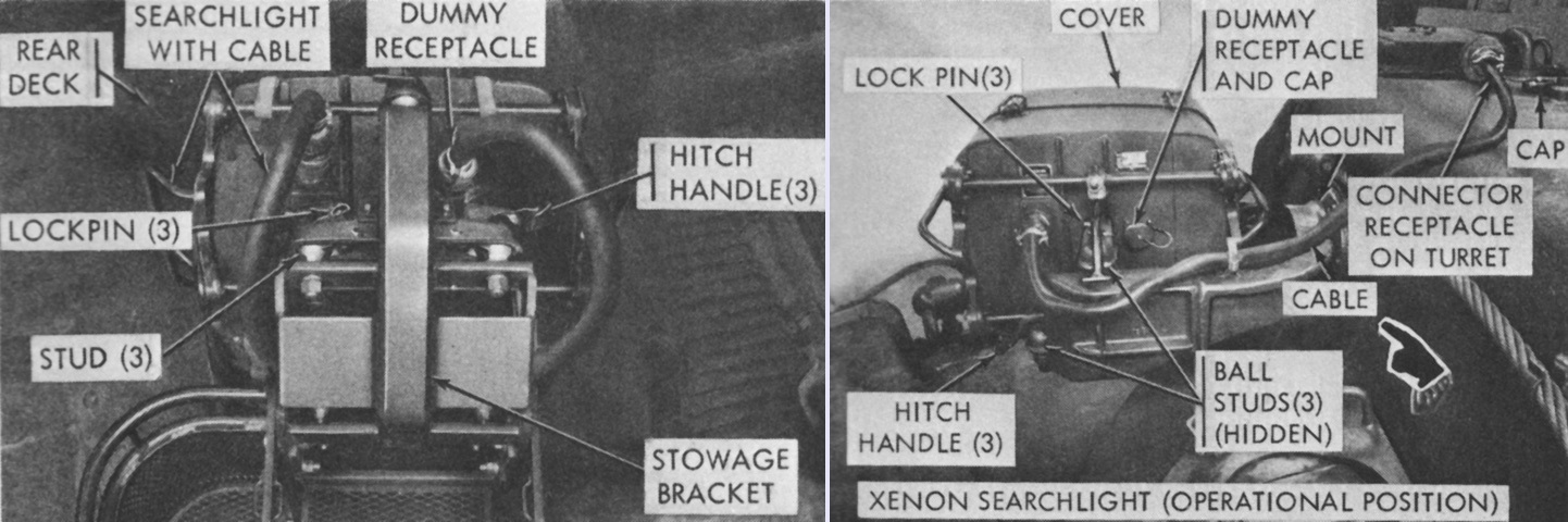
The searchlight is illustrated here stowed on the turret rear in the left image and mounted in the right image. The dummy receptacle was used to secure the end of the power cable that would mate with the power receptacle on the turret roof. Moving the searchlight could take some effort, as it weighed 230lb (104kg). (Picture from TM 9-2350-232-10 C3).
The loader's hatch is open here, and the thickness of the armor surrounding the hatch can be gleaned.
The absence of a bore evacuator on this gun-launcher indicates it is a later-production example. The searchlight is mounted on the turret left. (Picture from TM 9-2350-232-10 C3.)
This tank is also fitted with late gun-launcher. The searchlight mount on the left side of the turret can be better seen here. (Photo by Richard S. Eshleman.)
This rear view shows the bulge under the rear louvres caused by the addition of the CBSS. Across the back of the turret, from left to right, are a stowage basket, turret ventilator blower, and the stowage point for the searchlight. The large size of the commander's cupola can also be ascertained. (Photo by Richard S. Eshleman.)
A closer look at the characteristic bulge under the exhaust grilles present on CBSS-equipped tanks is provided here. There is a pronounced lip along the bottom of the grilles that overlaps this bulge. The presence of a bore evacuator chamber on the gun-launcher did not mean that CBSS was not present.
The bulge in the casting curved down toward the underside of the hull rear.
The thickness of the CBSS bulge can be gleaned from this image.
Seen from above, the narrowness of the turret compared to earlier designs is starkly apparent. Note the indentation in the engine cover above the rear grille doors; this was where the travel lock for tanks with the 105mm gun was installed. The shorter gun-launcher precluded its use. The lip at the bottom of the grille doors covering the CBSS bulge at the hull rear can also be seen. (Picture from TM 9-2350-232-10 C3.)
A top-down cross-section of the hull is drawn in this picture. Note the length of the missiles compared to the conventional shells in the ammunition stowage on both sides of the driver. (Picture from TM 9-2350-232-10 C3.)
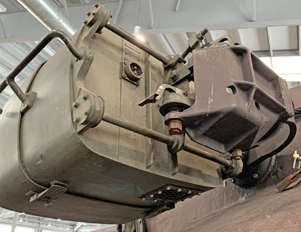
The combined engine and transmission are seen here dismounted. The closed-breech scavenging system found on later tanks was mounted on the lower rear end of the transmission. The introduction of this system came about due to issues with burning fragments of the combustible ammunition cases remaining in the gun breech after the round had been fired. (Picture from TM 9-2350-232-20-1.)
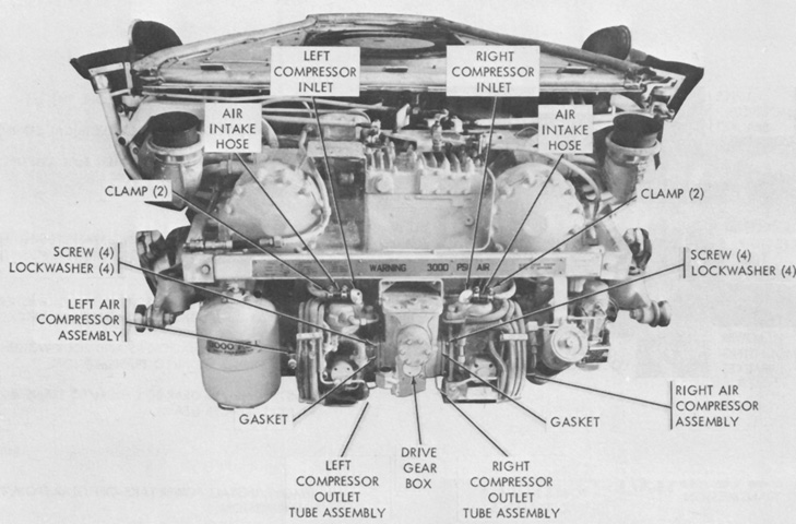
This view highlights the CBSS mounted on the transmission. Two air compressors were driven by a gearbox mounted on the transmission's power take-off; the compressor speed was proportional to engine speed, and the compressors would only engage at 750 engine rpm or higher. At the bottom left is a small air storage bottle, which accepted air from the compressors after it had passed through a chemical drier which removed water and oil vapor and solid particles. Any residual moisture condensed in this bottle, which had a bleed valve on the bottom. (Picture from TM 9-2350-232-20-1.)
The Cross-Drive transmission has been removed in this image, and the CBSS installation including the air compressors can be seen at the bottom rear of the assembly. The system would deliver three 1,000psi (70kg/cm²) shots of air after each main gun round fired. The system was triggered by the recoil of the gun-launcher. (Photo by Mark Halpin.)
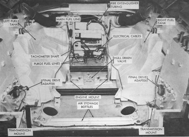
The engine compartment is seen with the powerpack removed. In addition to the assemblies attached to the transmission, the CBSS also involved two large air storage bottles found at the rear of the engine compartment. (Picture from TM 9-2350-232-20-1.)
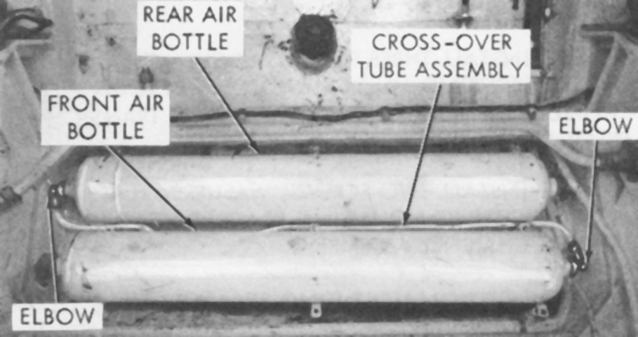
The combined volume of the two large air storage bottles and single small air storage bottles was 2,940in³ (48.2L). (Picture from TM 9-2350-232-20-1.)
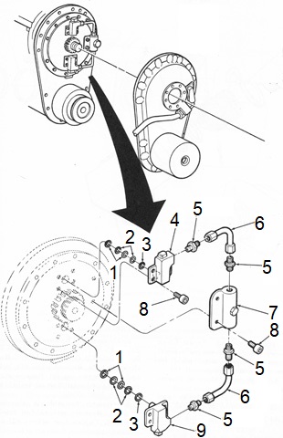
The CBSS valve block assemblies were installed on the breech rear and provided the nozzles through which the compressed air passed into the gun-launcher. 1. Packing, preformed (4). 2. Retainer, packing (4). 3. Retainer (2). 4. Valve block, upper. 5. Connector (4). 6. Tube assembly (2). 7. Tee assembly. 8. Screw, self-locking (10). 9. Valve block, lower. (Picture from TM 9-2350-232-34.)
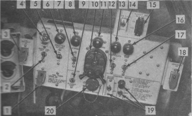
An on/off switch for the CBSS was added to the left side of the driver's master panel. Once activated, the system's pressure was maintained automatically by a pressure switch that disengaged the compressors at 3,000psi (210kg/cm²). 1. Fuel pumps switch. 2. Engine fuel shut-off spring-loaded toggle switch. 3. Gun scavenge switch. 4. Starter switch. 5. Master battery switch. 6. Master battery indicator. 7. Driver's infrared power pack switch. 8. Infrared power switch indicator. 9. Infrared/blackout light selector switch. 10. Lighting control switch. 11. Hi-beam indicator. 12. Gas particulate switch. 13. Gas particulate switch indicator. 14. Gas particulate circuit breaker. 15. Turret power aux circuit breaker. 16. Bilge pump indicator. 17. Bilge pump switch. 18. Generator switch. 19. Personnel heater switches and indicator. (Picture from TM 9-2350-232-10 C3.)
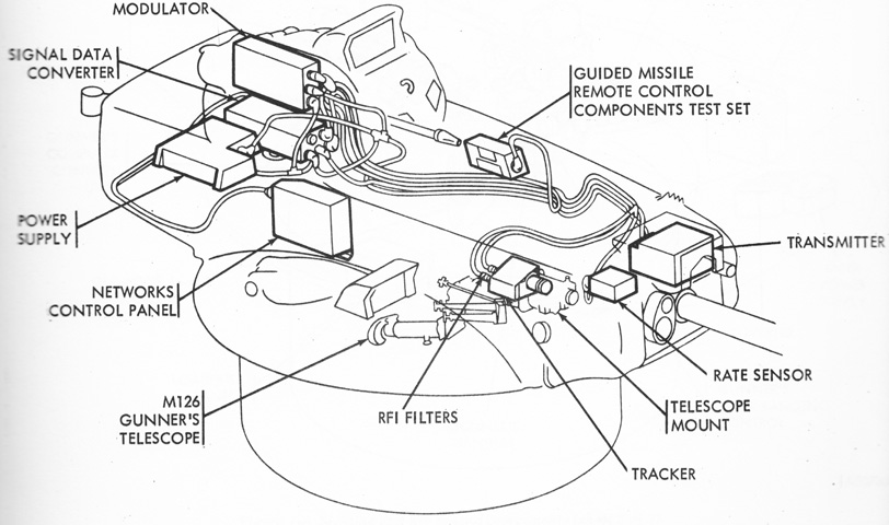
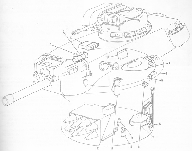
Components making up the sighting and fire control systems are sketched here. The power supply accepted electrical power from the vehicle's electrical system and regulated, converted, and distributed it to the guidance and control components. The infrared tracker measured how far the in-flight missile had deviated from line-of-sight and relayed that information to the signal data converter (SDC). The rate sensor produced signals that corresponded to the rate of turret traverse or gun elevation and sent them to the SDC. The SDC combined the signal output from the tracker and the rate sensor and computed the necessary corrections to keep the missile on the line-of-sight. These signals were sent to the modulator as missile command signals. The modulator converted the signals from the SDC into high current output to operate the transmitter. Finally, the transmitter converted the electrical signals received from the modulator into infrared signals and projected these to the missile as a narrow infrared beam. (Picture from TM 9-2350-232-10 C3.)
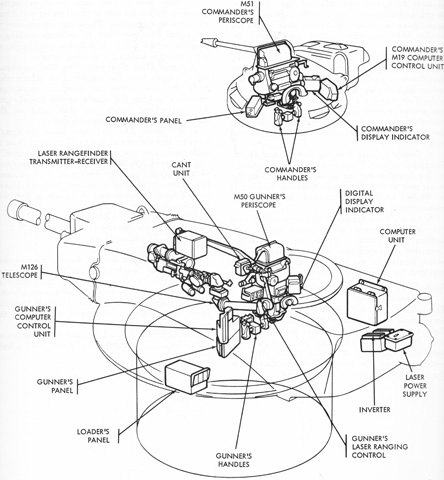
More fire control assemblies are labeled. (Picture from TM 9-2350-232-10 C3.)
Yet more fire control assemblies are labeled. (Picture from TM 9-2350-232-10 C3.)
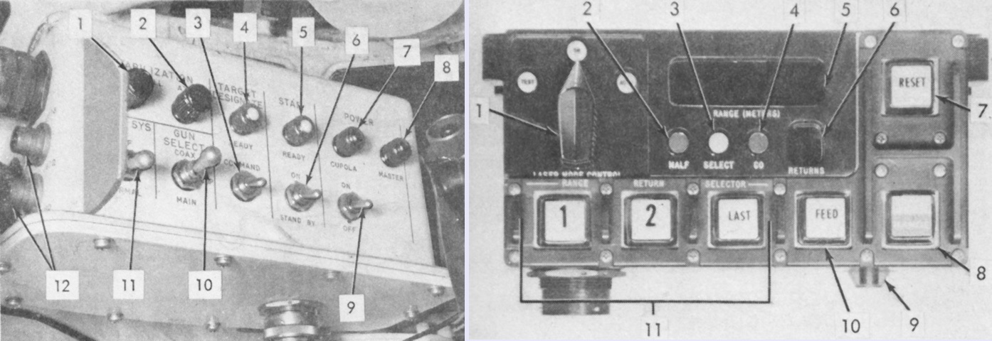
The commander's control panel and display command indicator are shown on the left and right, respectively. The legend for the control panel is: 1. Stabilization null-el [Provided stabilization elevation adjustment to eliminate drift of .50cal machine gun.]. 2. Stabilization null-az [Provided stabilization elevation adjustment to eliminate drift of cupola.]. 3. Target designate command switch [Caused turret to automatically align with cupola line-of-sight. The alignment could be aborted by putting switch in the down position.]. 4. Target designate-ready indicator light. 5. Stab-ready indicator light [Glowed when stabilization system experienced its required warm-up period and was in standby condition.]. 6. Stab on/standby switch. 7. Power-cupola indicator light. 8. Power-master indicator light. 9. Cupola and turret electrical power on/off switch. 10. Gun select--Cupola/Coaxial machine gun/Main [Spring-loaded in cupola position and held in main or coaxial positions when stabilization system was on. When Coaxial or Main was selected, the cupola would automatically align with turret and maintain this alignment. The commander could then take control of the turret and fire the main or coaxial guns.]. 11 Hydraulic system off/normal switch. 12. Intercom connectors.
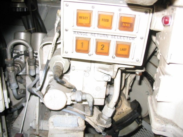
The legend for the display command indicator is: 1. Laser mode control [Only effective if the commander took control of the turret. Auto mode automatically inserted valid range result data into the computer; On mode required manual insertion of range data into the computer; Test mode enabled testing without firing the laser.]. 2. Malfunction light. 3. Select light [In Auto mode, indicated that reply count, target selection, and maximum range criteria had not been met, necessitating manual range input into the computer; in On mode, indicated that range needed to be inserted manually.]. 4. Go light [Indicated that range data of a selected target stored in the rangefinder had been made available to the computer.]. 5. Range indicator. 6. Returns indicator [Indicated number of target replies (maximum 8) for each ranging sequence.]. 7. Reset switch [Reset system between ranging sequences. The laser could not be fired until the reset switch was pressed. If gunner was controlling the turret, the commander's reset switch was inoperable.]. 8. Range switch [Laser fired when pressed.]. 9. Brightness control switch. 10. Feed switch [Transferred selected target range into the computer. The transfer needed to be manually initiated when the system was in On mode or criteria for automatic insertion had not been met. The commander's Feed switch would work when the gunner was in control of the turret.]. 11. Range return selector switch [to select the display and processing of first, second, or last return]. (Picture from TM 9-2350-232-10 C3.)
Upper and lower views of the commander's M19 ballistic computer control unit are provided here. The computer had minimum and maximum range limits of 300m and 4,000m (330yd and 4,3700yd), respectively, and could account for crosswinds of up to 40mph (64kph). 1. Main gun elevator boresight knob. 2. Main gun deflection boresight knob. 3. Cupola gun elevation boresight knob. 4. Cupola gun deflection boresight knob. 5. Wiper on-off switch. 6. Periscope power on-off switch. 7. Cant on-off switch. 8. Computer power on-off switch. 9. Override button, control-no-control indicators [Pushbutton transferred control to or from gunner's or commander's computer control units. Green light indicated commander control; red light indicated gunner control.]. 10 Bright-dim control knob. 11. Manual wind speed and direction input control knob. 12. Wind speed and direction indicator. 13. Wind speed and direction indicator light [Illuminated when power was on.]. 14. Target range control (manual). 15. Target range indicator. 16. Target range indicator light [Illuminated with power was on.]. 17. Ammunition selector pushbutton switches and indicators. (Picture from TM 9-2350-232-10 C3.)
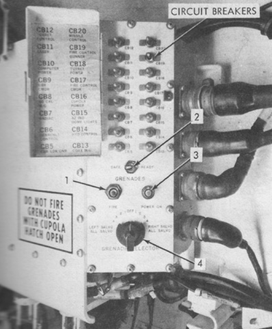
The grenade launcher control panel was located on the networks control panel. The grenade launchers could be fired individually, all at once, or in a salvo of all of the right or left launchers. 1. Fire pushbutton switch. 2. Grenades safe/ready switch. 3. Power on light. 4. Grenade selector. (Picture from TM 9-2350-232-10 C3.)
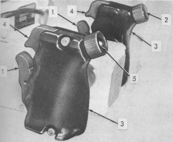
The commander's handles are detailed in this image. 1. Palm switches [Completed firing circuit in conjunction with triggers. In Stabilized mode, for either Main or Coaxial guns, the commander's palm switches would override the gunner's control of the turret. In Power mode, the palm switches released the cupola traverse brake.]. 2. Right lead switch [Pressed to introduce a target lead angle of up to 30mph (48kph) at 325m (1,070') in Stabilized mode with the Main gun selected when the commander's ballistic computer override was pressed. After tracking the target for 1 second, pressing the right lead switch moved the sight reticle the computed distance. The lead automatically dropped out after 30 seconds.]. 3. Handles. 4. Trigger. 5. Left lead switch [Cancelled lead applied by right lead switch; fired laser.]. (Picture from TM 9-2350-232-10 C3.)
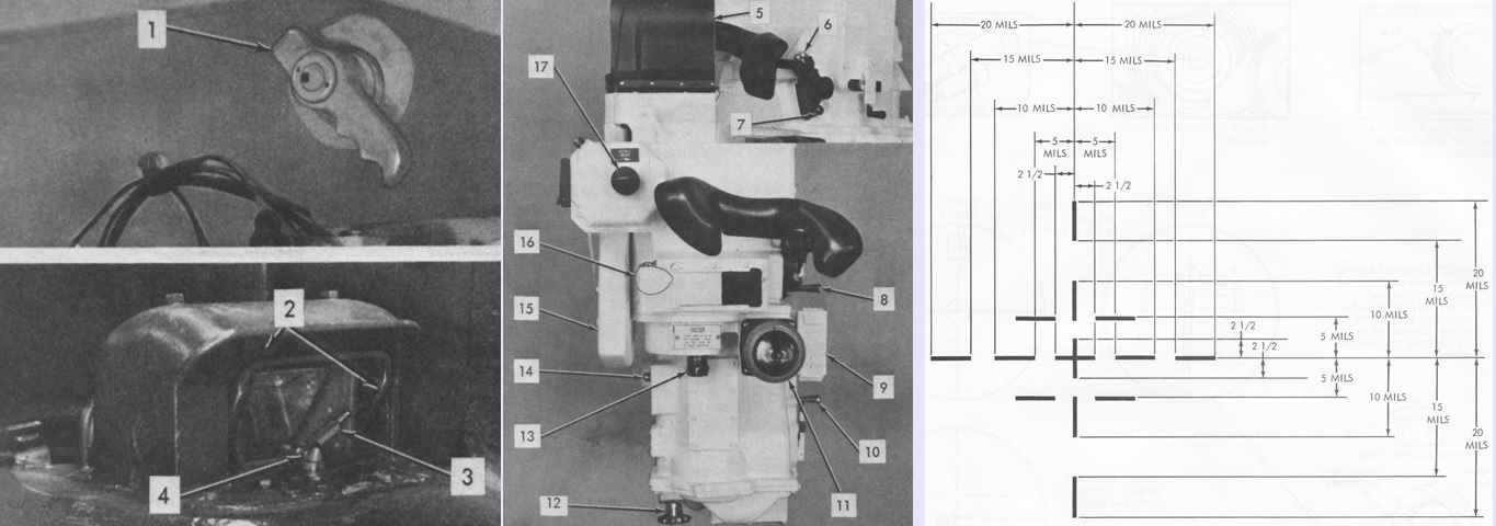
The commander's periscope M51 is detailed in these images, with the reticle drawn on the right. It was used to align the target when using the .50cal machine gun and could also be used to aim the coaxial machine gun and 152mm gun-launcher. In daylight operation, it featured a 27°x9° field of view unity power window and an 8x magnification with an 8° field of view. The passive night vision system used 10x magnification with a 5½° field of view. 1. Shield actuating handle. 2. Guard and shield assembly. 3. Wiper assembly. 4. Washer assembly [hand-actuated pump]. 5. Head assembly. 6. Reticle illumination knob. 7. Headrest lock lever [to lock headrest in raised position to expose unity window or lowered position to cover unity window]. 8. Headrest adjustment lever. 9. Flip mirror lever [to change between 8x daylight or 10x passive night vision]. 10. Diopter knob. 11. Focus knob. 12. Laser filter stowage box. 13. Passive on indicator light. 14. Unity power window and cover. 15. Filter knob [Actuated a four-position filter disc: off, 1 (dense), 2 (neutral), and 3 (clear).]. (Picture from TM 9-2350-232-10 C3.)
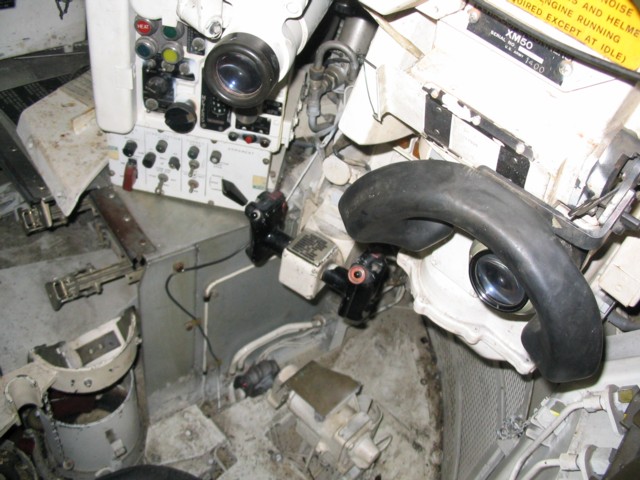
This view is up into the commander's cupola. The microphone and intercom control box are visible on the turret wall, and the cupola traverse mechanism is behind the commander's left shoulder.
This view highlights the commander's control panel on the left side of his cupola. His handles are visible in the bottom of the image, and the headrest for his M51 periscope is above the handles.
The right side of the commander's cupola is shown here with the M19 ballistic computer control unit in the center of the image. Some of the eleven vision blocks ringing the base of the cupola are visible, and the M51 periscope is on the left of the image. Below the periscope eyepiece and headrest, part of the display command indicator can be seen.
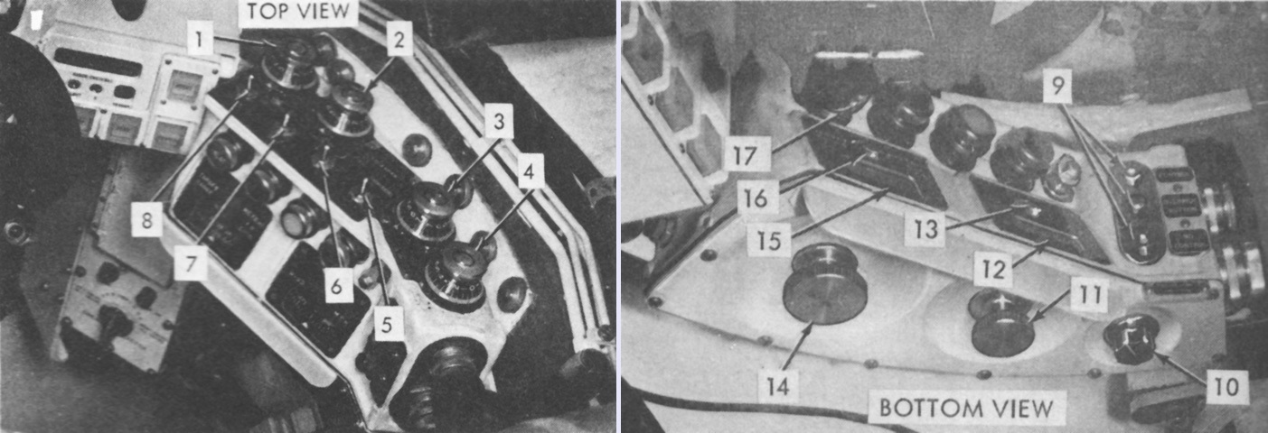
The gunner's controls and equipment are labeled in these pictures. 1. 7.62 mm machine gun. 2. 152 mm gun launcher. 3. Transmitter door handle (manual). 4. Telescope and rangefinder ballistic covers handle. 5. M50 periscope shield actuating handle. 6. Data transmission linkage assembly. 7. M13A1 elevation quadrant. 8. M126 telescope. 9. M50 periscope. 10. Digital display indicator. 11. System pressure gage. 12. Equilibrator pressure gage. 13. M3 filter unit hose (to air heater). 14. Turret power valve. 15. Equilibrator system pressure valve. 16. Screwdriver (checksight adjustment). 17. Seat. 18. Main gun elevation/depression pump. 19. Turret traversing handle (manual). 20. Gunner's handles. 21. Gunner's panel. 22. M19 computer control unit. 23. Gunner's lasing ranging control. 24. Azimuth indicator. 25. Oldham coupling. (Picture from TM 9-2350-232-10 C3.)
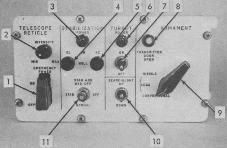
The gunner's panel is isolated in this image. 1. Emergency power on/off. 2. Telescope reticle intensity min/max knob. 3. Stabilization on indicator light. 4. El null [Provided adjustment to eliminate gun launcher drift in elevation.]. 5. Az null [Provided adjustment to eliminate turret drift in azimuth.]. 6. Turret power indicator. 7. Turret power on/off switch. 8. Transmitter door open indicator. 9. Armament selector [Conventional/Coax/Missile; when hydraulic power was available, Missile position automatically opened transmitter door.]. 10. Searchlight up/down adjustment. 11. Stab & hydr off/Stab off/Normal selector switch [Provided option to turn off stabilization only or both stabilization and hydraulic power.]. (Picture from TM 9-2350-232-10 C3.)
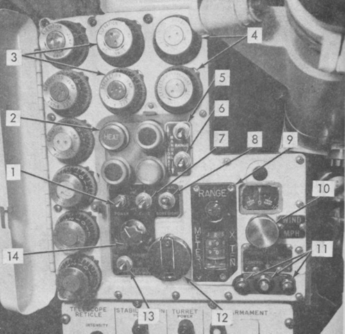
The gunner's M19 ballistics computer control unit is labeled here. 1. Computer power on/off switch. 2. Ammunition selector pushbutton switches/indicators. 3. Elevation/deflection jump knobs [Each ammunition type had an elevation and deflection jump knob which were color-coded to match the ammunition select switches and were used for jump adjustment (zeroing).]. 4. Elevation/deflection boresight knobs. 5. Automatic/manual range input switch. 6. Automatic/manual wind input switch. 7. Cant correction on/off switch. 8. Normal/boresight switch. 9. Range indicator in meters x ten. 10. Wind speed and direction input knob (manual) and indicator. 11. Override button, control-no-control indicators [Pushbutton switch transferred control to or from gunner's or commander's control unit. Green light indicated control, while red light indicated no control at that station.]. 12. Manual range input crank. 13. Periscope/periscope and wiper on/off switch. 14. Panel lights bright/dim control knob. (Picture from TM 9-2350-232-10 C3.)
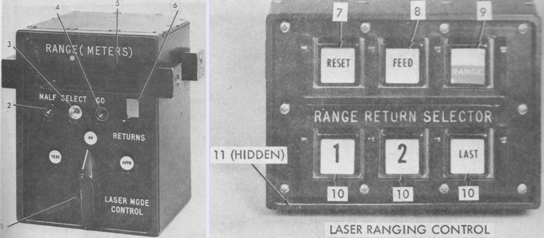
The gunner's display digital indicator is on the left in the image above, and the laser ranging control is on the right. 1. Laser mode control [Auto/On/Test switch was only effective when gunner had control, but lights illuminated to indicate mode selected when either gunner or commander had control.]. 2. Malfunction light. 3. Select light [In Auto mode, indicated that reply count, target selection, and maximum range criteria were not met, and range information needed to be manually inserted into computer; in On mode, indicated that range needed to be inserted manually.]. 4. Go light [Indicated that range data of selected target stored in the rangefinder had been fed to the computer.]. 5. Range indicator. 6. Returns indicator [Indicated the number of target replies (up to 8) for each ranging sequence.]. 7. Reset pushbutton switch [Reset the system prior to next ranging operation. Transmitter could not be fired until Reset button was pressed. Only active if gunner had control.]. 8. Feed pushbutton switch [Transferred selected target range into the computer. The transfer needed to be manually initiated when the system was in On mode, or when conditions existed that prevented the automatic transfer into the computer. The switch was active at all times.]. 9. Range pushbutton switch [Backlit with white top half and red bottom half; bottom half flashed and was active only when gunner was in control.]. 10. Range return selector pushbutton switches [Allowed the choice of first, second, or last of up to three replies for range display and processing.]. 11. Brightness control switch. (Picture from TM 9-2350-232-10 C3.)
The gunner's laser ranging control unit was located just to the left of his periscope.
The gunner's handles are illustrated here. 1. Palm switches [Completed firing circuit in conjunction with firing triggers; released the turret azimuth brake in power mode.]. 2. Right lead switch [Pressed to introduce a target lead angle of up to 30mph (48kph) at 325m (1,070') in Stabilized mode with the Main gun selected when the gunner's ballistic computer override was pressed. After tracking the target for 1 second, pressing the right lead switch moved the sight reticle the computed distance. The lead automatically dropped out after 30 seconds.] 3. Handles. 4. Trigger. 5. Left lead switch [Cancelled lead applied by right lead switch; fired laser.]. (Picture from TM 9-2350-232-10 C3.)
The gunner's periscope M50 is detailed in these images. For daylight use its unity power window had a 22° horizontal and 6½° vertical field of view, and its 8x magnification had an 8° field of view. Its 10x passive night system had a 5½° field of view. Its reticle is detailed on the right. 1. Shield actuating handle. 2. Guard and shield assembly. 3. Wiper assembly. 4. Washer assembly [hand actuated pump]. 5. Head assembly. 6. Headrest locking lever [to lock headrest in raised position to expose unity window or lowered position to view through the eyepiece]. 7. Headrest adjusting lever. 8. Flip mirror lever #1 [to change between 1x and 8x daylight operation]. 9. Laser filter stowage box. 10. Flip mirror lever #2 [to change between daylight and night operation]. 11. Diopter ring. 12. Focus knob. 13. Filter knob [Actuated a four-position filter disc: off, 1 (dense), 2 (neutral), and 3 (clear).]. 14. Passive on indicator light. 15. Unity power window cover stowage clip. 16. Unity power window. 17. Reticle illumination knob. (Picture from TM 9-2350-232-10 C3.)
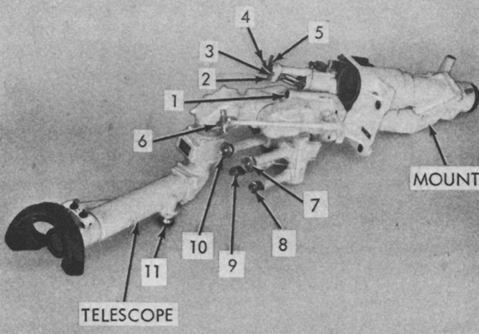
The gunner's telescope M126 and telescope mount M153 are labeled in this picture. The M126 provided 8x magnification with an 8° field of view. The M153 also supported the missile tracker and incorporated a checksight to optically align the missile reticle with the tracker. 1. Parallax adjustment. 2. El rotary adjustment [Provided the checksight aperture adjustment in elevation to locate tracker null axis.]. 3. Az rotary adjustment [Provided the checksight aperture adjustment in azimuth to locate tracker null axis.]. 4. Align lever [Erected a prism in the mount to check alignment of optical tracker with telescope.]. 5. Error lever [Introduced an alignment error during system self-test to simulate missile deviation from line-of-sight.]. 6. Filter selector control knob [to select clear, neutral, or laser filters]. 7. Defl rotary adjustment [Allowed conventional reticle to be adjusted ±7.5 mils in deflection for boresighting and zeroing conventional ammunition.]. 8. Horizontal rotary adjustment [Provided missile reticle adjustment in azimuth.]. 9. Vertical rotary adjustment [Provided missile reticle adjustment in elevation.]. 10. Elev rotary adjustment [Allowed conventional reticle to be adjusted ±7.5 mils in elevation for boresighting and zeroing conventional ammunition.]. 11. Diopter rotary adjustment. (Picture from TM 9-2350-232-10 C3.)
The reticles used with the telescope M126 are drawn above. The left reticle was for missiles, while the right was for conventional ammunition. The appropriate reticle was displayed depending on the position of the armament selector switch. The short horizontal line below the missile aiming cross was the terrain interference line. If a terrain obstacle in the missile line-of-sight within 500m of the tank extended above this line, the missile was not to be fired. The upper cross inside the square on the missile reticle was used during boresighting. The stadia lines for the conventional reticle were calibrated for average enemy tanks that were ~10' (~3m) wide and ~20' (~6m) long, so that such a target broadside to the gunner could be ranged by a full choke with both stadia lines, while a target facing directly toward or away from the gunner could be ranged with a half choke using one stadia line and the central vertical range line. (Picture from TM 9-2350-232-10 C3.)
The reticles for the periscopes are diagrammed while aiming at the upper left corner of a window for boresighting, while the telescope reticles are again displayed. (Picture from TM 9-2350-232-10 C3.)
The gunner's controls are shown here. His handles are obvious in the middle of the image, and to the left is his panel and computer control unit. The M126 telescope is above the gunner's panel, and his periscope M50 is to the right of his handles. The ammunition box in the center of the turret floor was used to stow eight conventional rounds.
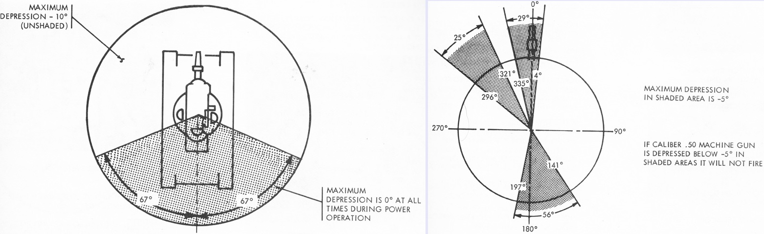
Depression limits are drawn for the gun-launcher on the left and the commander's .50cal machine gun on the right. (Picture from TM 9-2350-232-10 C3.)
Controls and equipment at the loader's station are sketched here. 1. Replenisher (indicator tape). 2. Main gun breech. 3. Loader's hatch. 4. Frequency selector C2742/VRC. 5. Intercommunication control C2298/VRC. 6. M3 filter unit air heater. 7. Loader's seat. 8. Turret mechanical lock. 9. Hydraulic hand pump. 10. Blasting machine. 11. Portable fire extinguisher. 12. Loader's panel. 13. Periscope M37 (stowage box). 14. Guided missile remote control components test set. (Picture from TM 9-2350-232-10 C3.)
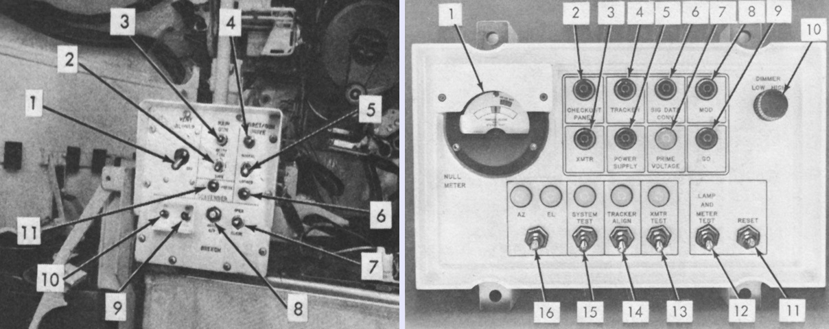
The loader's panel is on the left of the image, and the guided missile remote control components test set (test check-out panel) is on the right. The legend for the loader's panel is: 1. Turret ventilator blower on/off switch. 2. Main gun ready fire/safe switch. 3. Ready fire indicator. 4. Normal indicator [Indicated gun-launcher firing circuit turret/gun drive switch were in Normal position.]. 5. Turret/gun drive switch [Normal position allowed for gun-launcher firing and automatic opening of breech. Locked position de-energized firing circuit and prevented turret and gun motion.]. 6. Locked indicator. 7. Breech electrical open/close switch. 8. Breech motor circuit breaker switch. 9. Breech control circuit breaker switch. 10. Radio circuit breaker switch. 11. Scavenger low pressure indicator [Illuminated when CBSS pressure dropped below 1,000psi (70kg/cm²), which was insufficient to scavenge gun-launcher after firing.].
The legend for the test check-out panel is: 1. Null meter [Indicated alignment of tracker during tracker alignment test and operational condition of rate sensor.]. 2. Checkout panel light [Indicated no/go condition of test checkout panel at the end of a system self-test.]. 3. Xmtr light [Indicated no/go condition of transmitter at the end of a system self-test.]. 4. Tracker light [Indicated no/go condition of tracker at the end of a system self-test.]. 5. Power supply light [Illuminated after system warm-up if power supply was inoperational.]. 6. Sig data conv light [Indicated no/go condition of signal data converter at the end of a system self-test.]. 7. Prime voltage light [Illuminated after system warm-up if vehicle power to the system was insufficient or excessive.]. 8. Mod light [Indicated no/go condition of modulator at the end of a system self-test.]. 9. Go light [Indicated operational go condition of guidance and control system at the end of a system self-test.]. 10. Dimmer control. 11. Reset switch. 12. Lamp and meter test switch. 13. Xmtr test switch and light. 14. Tracker align switch and light. 15. System test switch and light. 16. Az/El switch and light [Selected azimuth or elevation signals from the rate sensor and displayed these on the null meter during the tracker alignment test to indicate azimuth or elevation alignment.]. (Picture from TM 9-2350-232-10 C3.)
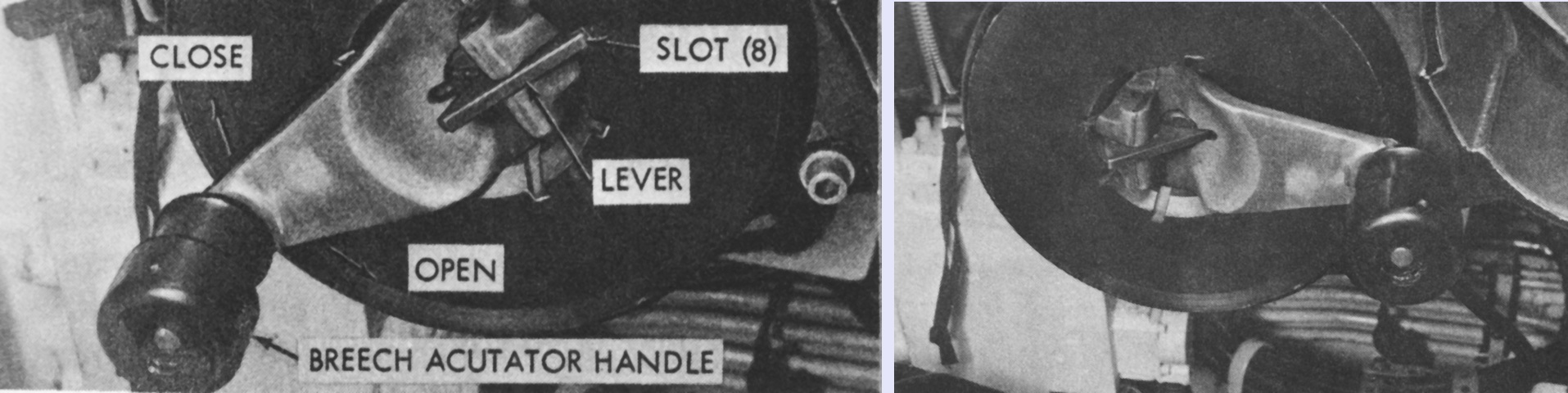
When operating the breech electrically, the hand crank lock lever needed to engage one of eight slots in the rear cover of the breech, as seen on the left. The breech open/close switch was held in the Open or Close position until the breech was fully opened or closed, at which point the electrical motor would automatically turn off.
To manually operate the breech, the lock lever needed to engage the slot in the end of the spindle visible in the center of the handle casting, as shown on the right. The breech actuating handle was then turned counterclockwise to open the breech until a mechanical stop was encountered. Closing the breech manually was accomplished by turning the handle clockwise until contacting a mechanical stop. (Picture from TM 9-2350-232-10 C3.)
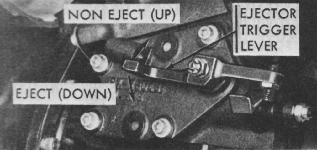
When firing a conventional round, the missile aft cap ejector trigger lever needed to be placed in the up, or non-eject, position. Missiles required the lever to be in the eject, or down, position. If the ejector was triggered when using a conventional round, the possibility existed of the case becoming damaged if unloading was required. (Picture from TM 9-2350-232-10 C3.)
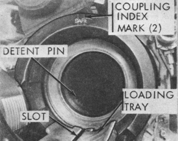
The gun-launcher breech is open in this picture. Loading a conventional round involved placing it on the loading tray and pushing it into the breech until the detent pin engaged. A missile required more precision: it was positioned so that a white index stripe was facing upwards. This would ensure that the missile key engaged the slot in the loading tray and the keyway in the gun-launcher. The missile could then be pushed into the breech until the detent pin engaged. An index mark on the breechblock that lined up between the two index marks on the coupling was used as a visual check that the breech was closed. (Picture from TM 9-2350-232-10 C3.)
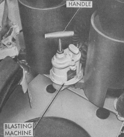
In the event of a power failure, the gun-launcher or grenade launchers could be energized for firing by using the blasting machine. Preliminarily, the main gun switch on the loader's panel needed to be placed and held in the Ready Fire position, or the selector on the grenade panel needed to be placed in the desired position and the grenade switch on the networks control panel placed in the ready position, and then the handle on the blasting machine was twisted violently until the gun-launcher or grenade launcher fired. Only one grenade launcher at a time would fire, however. (Picture from TM 9-2350-232-10 C3.)
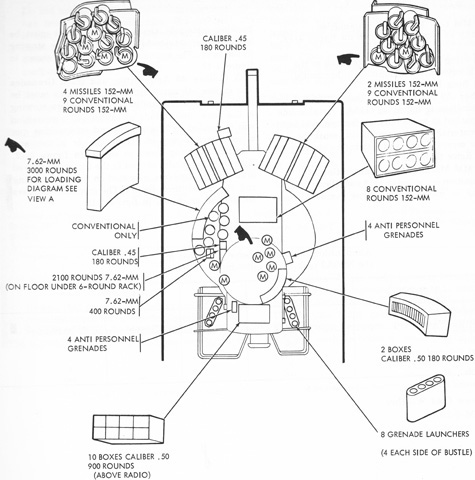
Ammunition stowage is sketched in this drawing. Missiles are denoted with an M. (Picture from TM 9-2350-232-10 C3.)
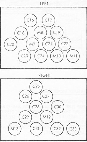
A tubular, stacked, welded, aluminum ammunition rack was installed on each side of the driver. The stowage diagrams for these racks is drawn above, with "C" denoting a conventional round and "M" a missile. Optional adapters enabled the missile tubes to be used for conventional ammunition instead if desired. (Picture from TM 9-2350-232-20-1.)
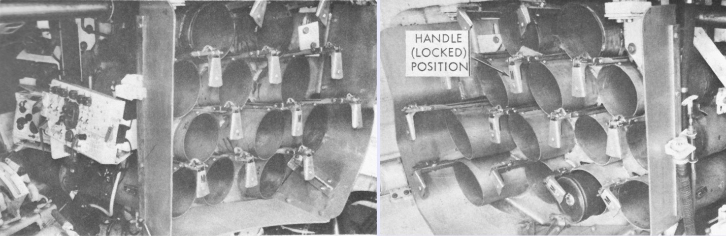
The right and left hull ammunition racks are seen installed in the left and right images, respectively. The driver's position is visible in the left image. (Picture from TM 9-2350-232-10 C3.)
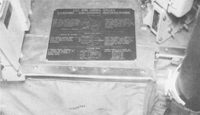
The horizontal conventional ammunition stowage rack on the turret platform functioned like the two hull racks. (Picture from TM 9-2350-232-10 C3.)
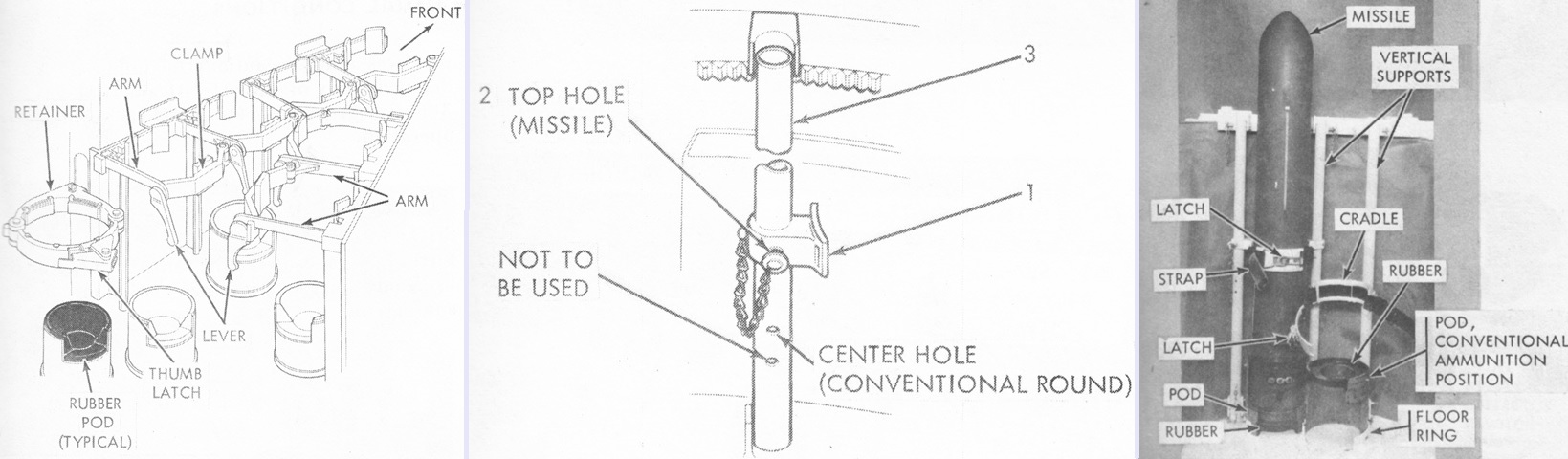
Convertible ammunition racks were installed on the turret platform. These could be configured to accept conventional ammunition or the longer missiles. As seen in the center sketch, the clamp (1) could be adjusted to either of the top two holes on the vertical support (3) and secured with a pin (2). When stowing conventional rounds, these were inserted into the rack nose-down into the rubber pod. Missiles, however, were stowed nose-up. (Picture from TM 9-2350-232-10 C3.)
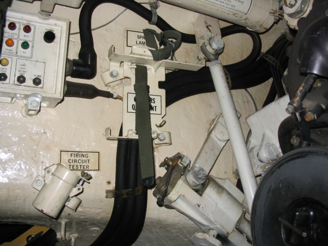
This view is looking across the turret to the loader's position. Stowage for the firing circuit tester, gunner's quadrant, and spare lamp are labeled, and the test check-out panel is visible mounted on the left turret wall. The breech of the 152mm gun-launcher is on the right of the picture.
Six 12-volt batteries were connected to make a 24-volt system. The batteries could be accessed through a door in the turret platform floor, as seen on the right. (Picture from TM 9-2350-232-10 C3.)
The M13A1 tank gas particulate filter system is diagrammed here. It was used in conjunction with the crew's individual M25A1 masks. (Picture from TM 9-2350-232-10 C3.)
A cross-section of the MGM-51C Shillelagh missile is drawn here. The MGM-51C had a shallower key than the MGM-51A or MGM-51B, and was the only type compatible with the gun-launcher M162. The key can be seen on the underside of the missile beginning about halfway from the front of the warhead section. The Shillelagh was a solid-propellant missile that was guided by an infrared datalink. The GM, HE, M131 warhead contained a shaped-charge using Octol high-explosive. The safety and arming (S and A) device was activated upon firing with the powering-on of the onboard batteries. The missile's acceleration caused a gear train to rotate the lead charge into alignment with the detonator. Impact closed the detonation circuit via a crush switch in the nose cone, and the batteries then supplied the detonator with electrical power. Four aluminum fins were stowed in the recessed aft body section and would unfold via springs during flight. The aft body section was protected by the aft cover assembly. The aft cover was attached to the aft body section by six aluminum screws that sheared when pressure from the rocket motor reached 250psi (18kg/cm²), releasing the missile from the aft cover assembly. The aft covers were reusable. (Picture from TM 9-2350-232-10 C3.)
Details of the top of the tank can be seen in this image. (Picture from TM 9-2350-253-20-2 C6.)
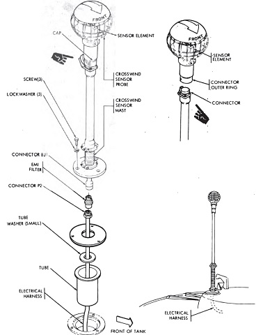
The mounting of the crosswind sensor is detailed here. (Picture from TM 9-2350-253-20-2 C6.)
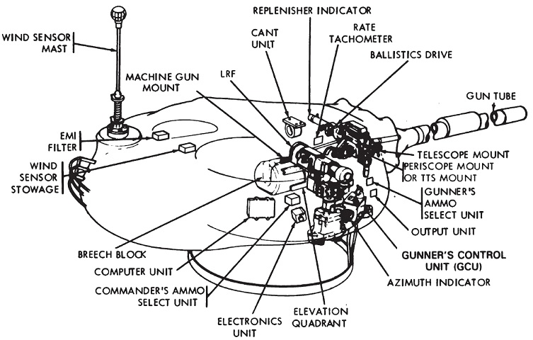
The positioning of some turret components are sketched for us here. (Picture from TM 9-2350-253-20-2 C6.)
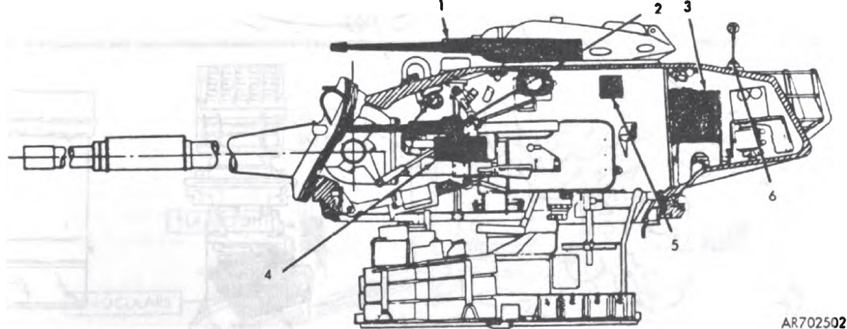
The key for the above diagram is: 1. M85 machine gun in commander's cupola. 2. M240 machine gun. 3. Radios in turret bustle. 4. Brass receptacle container on co-axial machine gun mount. 5. Interphone and control boxes. 6. Antennas and wind sensor mast. (Picture from TM 9-2350-253-20-2 C6.)
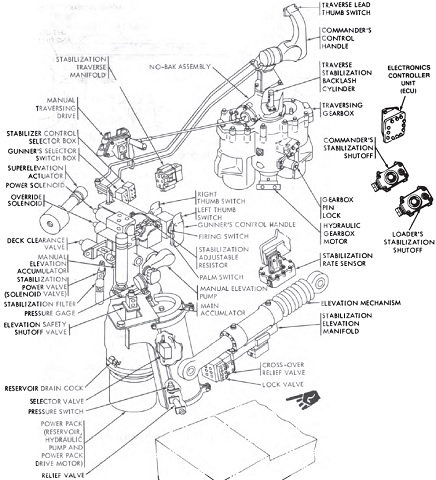
The various components of the turret and gun control system are diagrammed here. (Picture from TM 9-2350-253-20-2 C6.)
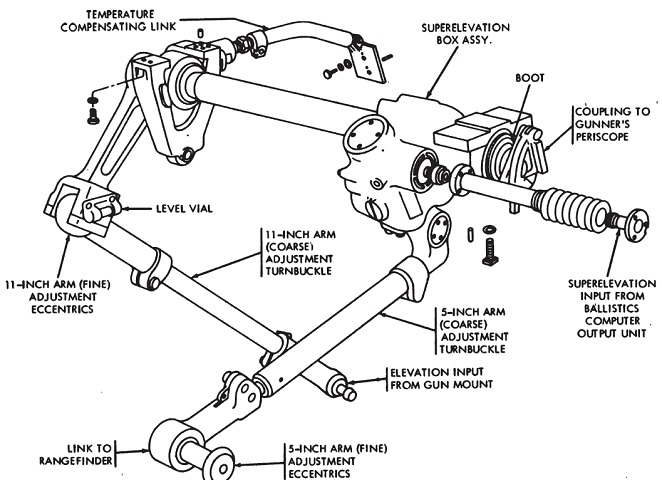
Details of the tank's ballistics drive are drawn in this picture. This assembly mechanically connected the gunner's periscopes and laser rangefinder to the gun mount in order to keep them synchronized. The ballistics drive also added superelevation from the computer output unit and changed the line-of-sight of the gunner's periscopes and rangefinder according to this superelevation. (Picture from TM 9-2350-253-20-2 C6.)
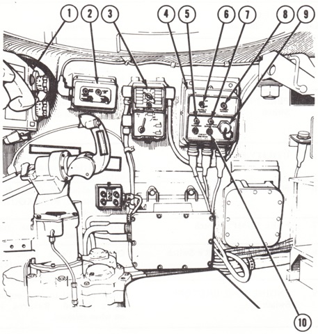
The commander's controls and indicators are shown in the following drawings. 1. Laser rangefinder receiver-transmitter. 2. Searchlight remote control (passive). 3. Frequency selector C-2742/VRC. 4. Networks box. 5. Stabilization electronics indicator. 6. Cupola power switch. 7. Power pack blower motor indicator. 8. Master power indicator. 9. Test connector (J4). 10. Power pack blower motor circuit breaker. (Picture from TM 9-2350-253-10 C12.)
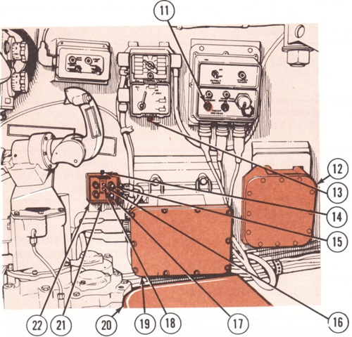
11. Stab electronics circuit breaker. 12. Stabilizer controller unit. 13. Intercom control C-2298/VRC. 14. Ammunition select unit lamp bright/dim control. 15. HEP/WP ammunition switch/indicator. 16. Moving indicator. 17. FSDS ammunition switch/indicator. 18. Stationary indicator. 19. XM21 computer. 20. Commander's seat. 21. Moving/stationary switch [Moving selected when the tank was moving or when the target was taking evasive action; stationary for when the tank and target were not moving or when the target was not taking evasive action]. 22. Ammunition select unit. (Picture from TM 9-2350-253-10 C12.)
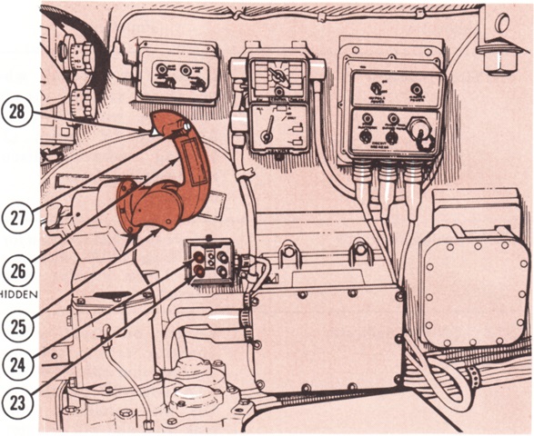
23. APDS ammunition switch/indicator. 24. HEAT ammunition switch/indicator. 25. Commander's control handle. 26. Palm switch. 27. Thumb switch [when held with palm switch depressed, offset the gunner's 8x daylight reticle and the azimuth mirror of the laser rangefinder at the commander's station to the computed lead value]. 28. Firing switch. (Picture from TM 9-2350-253-10 C12.)
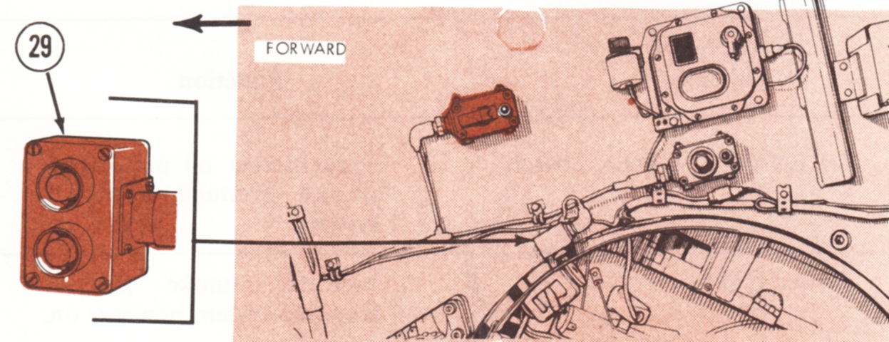
29. Push button unit that launched three smoke grenades from each discharger when a single switch was pressed, or all twelve grenades when both switches were pressed. (Picture from TM 9-2350-253-10 C12.)
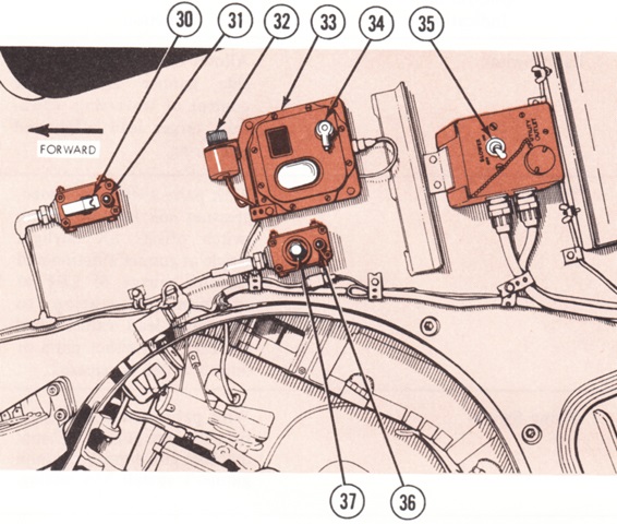
The turret roof at the commander's position is shown here. 30. Grenade power switch. 31. Smoke grenade launcher system power light. 32. Domelight brightness control. 33. Domelight. 34. Domelight power off/red light/white light control switch. 35. Turret ventilator blower switch. 36. Stabilization system on light. 37. Emergency stab shut-off switch. (Picture from TM 9-2350-253-10 C12.)
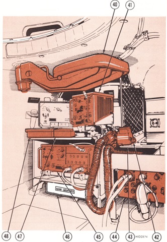
The rear of the commander's position is labeled in this drawing. 40. Observation seat. 41. Receiver R-442/VRC. 42. Gas-particulate filter unit air heater control. 43. Gas-particulate filter hose (orifice). 44. Searchlight control (passive). 45. Receiver-transmitter RT 246/VRC. 46. Grenade box. 47. Spare lamp box. 48. Spare bulb box. (Picture from TM 9-2350-253-10 C12.)
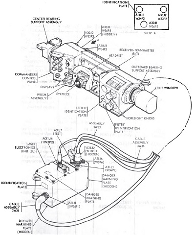
The internal components of the laser rangefinder are shown here. (Picture from TM 9-2350-253-20-2 C6.)
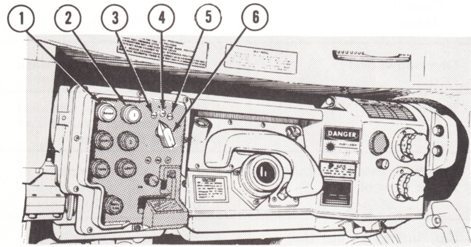
The commander's controls for the laser rangefinder are detailed here. The rangefinder had a maximum lasing rate of 6 rangings/minute for 2 minutes followed by a 3-minute wait, while 3 rangings/minute could be performed continuously. 1. Range switch/indicator. A steady red light indicated that the laser had been fired or was in test mode; or that the rangefinder was locked out by computer controls (manual mode). A flashing red light indicated that the laser was armed and could be fired by pressing the range switch or from the gunner's position. 2. 1 switch/indicator. When pressed, the switch attempted to select the first return. The selection was allowed if SEL was on or if both GO and SEL were off. 3. Test indicator. 4. On indicator. 5. Auto mode indicator. 6. Mode switch, to select test, on, or auto modes. (Picture from TM 9-2350-253-10 C12.)
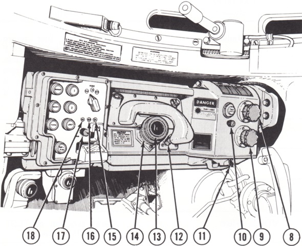
8. Deflection control. 9. Elevation control. 10. Reticle brightness control. 11. Filter bracket. 12. 6x/12x switch. 13. Eyepiece. 14. Diopter ring. 15. GO indicator. A green light indicated range data had been fed to the computer. 16. Malfunction indicator. 17. Light/dim/test control. 18. SEL indicator. An orange light indicated range data was not fed to the computer. Manual feeding of range or selection of replies was required. (Picture from TM 9-2350-253-10 C12.)
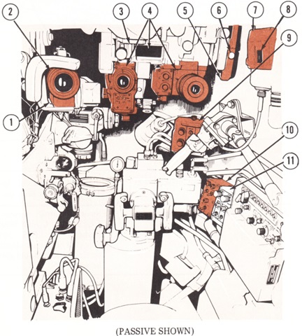
The gunner's position is labeled in this drawing. 1. Telescope M105D. 2. Diopter ring. 3. Periscope mount M118E1 (Passive). 4. M35E1 periscope (Passive). 5. Ballistic shield operating handle (Passive). 6. Lock plunger (Passive). 7. Output unit. 8. MIL counter. 9. Ammunition selector unit. 10. Gunner's switch box. 11. Stabilization control selector. (Picture from TM 9-2350-253-10 C12.)
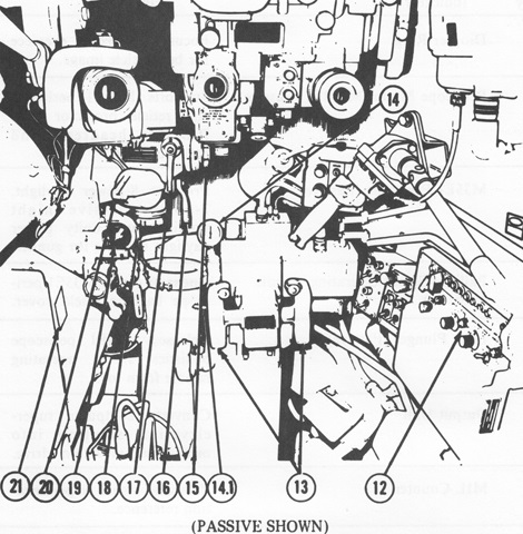
12. Gunner's control unit. 13. Gunner's control handles. 14. Accumulator pressure gage. 14.1. Hydraulic pressure selector (dump) valve control and indicator. 15. Deflection knob. 16. Elevation lock. 17. Deflection lock. 18. Elevation knob. 19. Light source control. 20. Filter box. 21. Aiming data chart. (Picture from TM 9-2350-253-10 C12.)
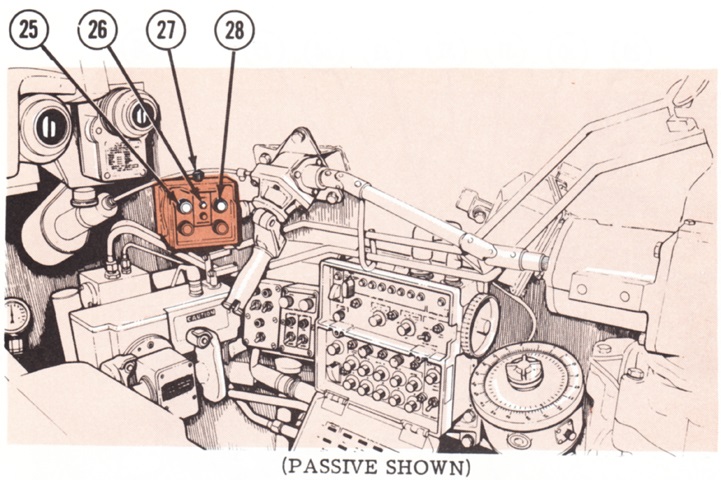
25. HEAT switch/indicator. 26. Moving indicator. 27. Bright/dim control. 28. HEP/WP switch/indicator. (Picture from TM 9-2350-253-10 C12.)
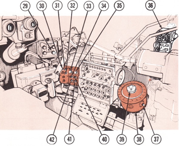
29. FSDS switch/indicator. 30. Main gun indicator. 31. Machine gun indicator. 32. Machine gun switch. 33. Trav balance knob [to control traverse drift while in stabilized mode]. 34. Stabilization power indicator. 35. Elev balance knob [to control elevation drift while in stabilized mode]. 36. Intercom control C-2298/VRC. 37. Azimuth indicator scale lamp rheostat knob. 38. M28E2 azimuth indicator. 39. Resetter knob. 40. Stab indicator. 41. Stab switch. 42. Stabilization system power switch. (Picture from TM 9-2350-253-10 C12.)
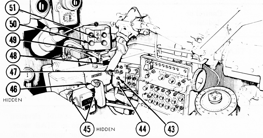
43. Elev/trav power indicator. 44. Elev/trav power switch. 45. Gunner's palm switches. 46. Firing triggers. 47. Main gun switch. 48. Manual traversing handle. 49. Moving/stationary switch. 50. APDS switch/indicator. 51. Stationary indicator. (Picture from TM 9-2350-253-10 C12.)
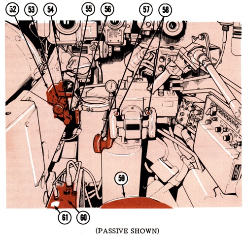
52. M13A1 elevation quadrant. 53. Elevation scale. 54. Elevation quadrant lamp rheostat control. 55. Level vial tube. 56. Manual firing handle (blasting machine). 57. Manual elevation handle. 58. Thumb switch [when pressed when palm switch was depressed, the laser was reset and fired, and the daylight body or TTS reticles and laser rangefinder mirrors were offset to the computed lead value]. 59. Gunner's seat. 60. Electronics unit. 61. Emer power switch [When on, power was supplied to the laser rangefinder when power to the computer was off. When off, laser rangefinder power was controlled by the power switch on the gunner's control unit.]. (Picture from TM 9-2350-253-10 C12.)
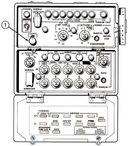
The gunner's control unit is shown in this sketch. 1. Red edge panel lights brightness control. In the upper left is the computer and laser system primary power indicator light, and the power switch is directly below the light. To the right of the power switch is the lamp/normal/system switch. It was sprung to the normal setting, and when rotated to the lamp setting illuminated all of the lamps and indicators in the control unit. When the system setting was selected, the computer underwent a self-test, the results of which were indicated on the self test indicators, and the laser rangefinder Range (meters) and Returns display. The series of lights across the top indicated, from left to right, an OK computer self test; a defective computer unit; a defective output unit; a defective reticle projector unit; a defective gunner's control unit; a defective cant unit; a defective laser rangefinder unit; and a defective or missing crosswind sensor, or that the system was being operated in manual wind mode. The air temp and altitude knobs were used to input those values into the computer. Panel lights are between and outside of these knobs, and five more are present on the lower portion of the unit. In the lower right corner of the upper section is the manual/rangefinder switch, which determined if the computer accepted input data from the rangefinder or the range dial on the right side of the gunner's control unit.
At the upper left of the lower section is the remaining tube life percentage control knob, and below this is the switch to put the system into boresight mode, where all computer functions except parallax and range were deactivated. The knob between the left and center panel lights at the top told the computer to calculate for either M728 or M392 APDS ammunition, while the knob to the right set the computer to calculate for M456 HEAT ammunition. The spare position on this knob was not used. At the right of the top row is the crosswind mph control to manually input crosswind speed from the right or left. The Common Zero column of knobs at the left offset all azimuth (top) or elevation (bottom) settings of individual controls by a fixed amount. To the right of these are the APDS azimuth (top) and elevation (bottom) zeroing controls. To the right of these are the HEP/WP azimuth and elevation zeroing controls, and to the right of these are the HEAT azimuth and elevation zeroing controls. The final column of knobs on the right are the FSDS azimuth and elevation zeroing controls. On the inside of the hinged cover at the bottom are areas to log the various settings used. (Picture from TM 9-2350-253-10 C12.)
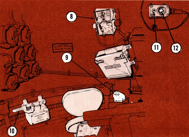
The loader's position is drawn here. 8. Interphone and control box. 9. Gas-particulate filter unit air heater control. 10. Traverse lock handle. 11. Stabilization system on light. 12. Emergency stab shut-off switch. (Picture from TM 9-2350-253-10 C12.)
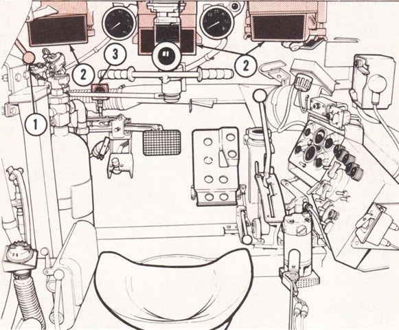
The driver's position is the subject of this and the following three sketches. 1. Driver hatch control. 2. M27 periscopes. 3. Brake pressure gage. (Picture from TM 9-2350-253-10 C12.)
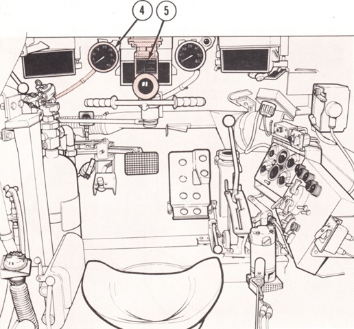
4. Tachometer/hour meter. 5. AN/VVS-2 driver's night vision viewer. (Picture from TM 9-2350-253-10 C12.)
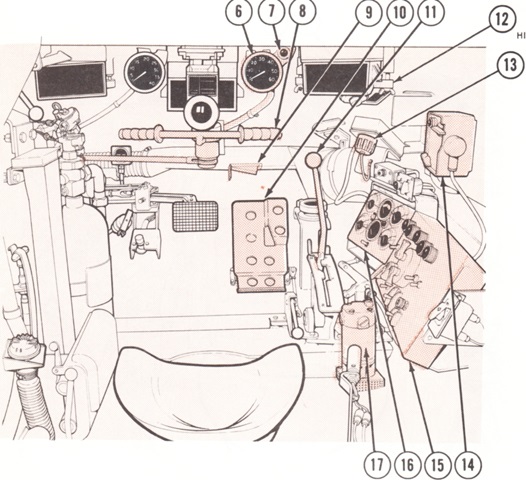
6. Speedometer/odometer. 7. Powerplant warning lamp. 8. Steering control. 9. Heater air outlet door. 10. Accelerator pedal. 11. Transmission shift lever. 12. Domelight. 13. Slave receptacle. 14. Intercom control. 15. Master control panel. 16. Indicator panel. 17. Bilge pump. (Picture from TM 9-2350-253-10 C12.)
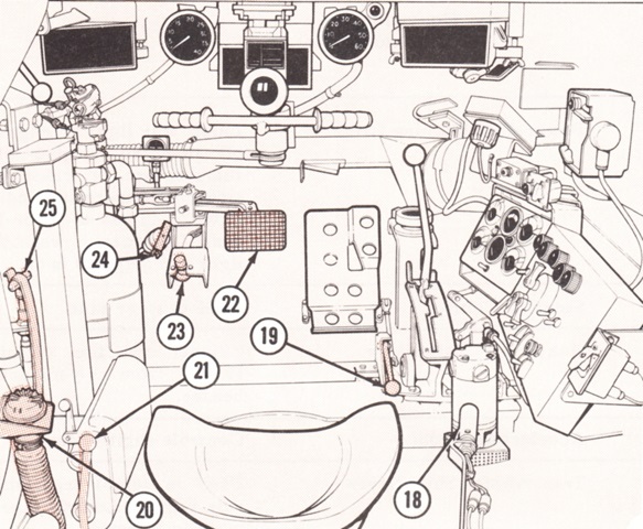
18. Purge pump/manifold heater switch (located on end of purge pump handle). 19. Accelerator lock lever. 20. Gas-particulate filter hose (orifice). 21. Driver's seat control levers (4). 22. Brake pedal. 23. Headlight dimmer switch. 24. Turret seal pump. 25. Manual fuel shutoff handle with latch. (Picture from TM 9-2350-253-10 C12.)
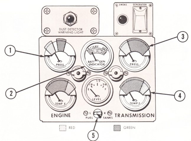
The driver's indicator panel is labeled here. 1. Engine oil pressure. 2. Battery-generator. 3. Transmission oil pressure. 4. Transmission oil temperature. 5. Fuel tanks selector switch. Under the battery-generator indicator is the fuel level gage for the selected tank. In the bottom left corner is the engine oil temperature gage. The dust detector warning light at the top left (if equipped) illuminated when dust detector pressure switches in the engine compartment tripped. The engine smoke generator switch at the top right was located under a protective cover, which was lifted to reveal the switch. The smoke generator was to be used with at least 1,600 engine rpm, and it was also not to be used in a building or enclosed area, when personnel were near, or when the tank's fuel supply was low. The indicator light to the left of the switch illuminated when the smoke generator was on. (Picture from TM 9-2350-253-10 C12.)
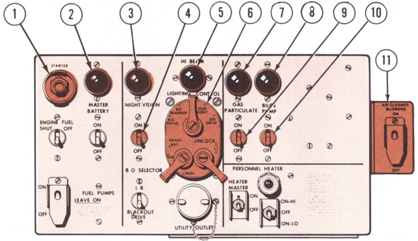
The driver's master control panel is drawn. 1. Starter switch. 2. Master battery indicator. 3. Night vision indicator. 4. Driver's night vision viewer power switch. 5. Hi beam indicator. 6. Lighting control. 7. Gas-particulate filter unit indicator. 8. Bilge pump indicator. 9. Gas-particulate filter unit switch. 10. Bilge pump switch. 11. Air cleaner blower switch. In the bottom right, the personnel heater master switch turned power on to the personnel heater switch. A 24-volt utility outlet is below the lighting control, and to the left of the utility outlet is the infrared headlight/blackout drive lights switch. The fuel pumps power switch is at the lower left, and directly above is the engine fuel shutoff switch. To the right of this is the master battery switch. (Picture from TM 9-2350-253-10 C12.)
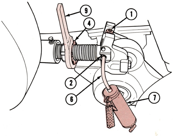
A new track tension adjustment mechanism was introduced, where grease pressure was used to move the idler wheel instead of a wrench. 1. Pressure relief valve. 2. Grease fitting. 4. Locking collar [shown loosened]. 6. Lube gun extension. 7. Grease gun. 9. Spanner wrench. (Picture from TM 9-2350-253-10 C12.)
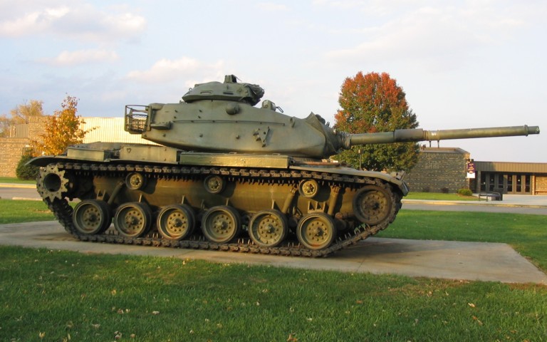
This tank is externally similar to the M60A1 above. Friction snubbers on the first two and last road wheels are obvious. The front road wheel arm was equipped with double bump stops, compared to single bump stops on the other wheels. The single bump stops can be seen behind the road wheels. The exhaust pipe for the personnel heater can be seen in front of the forward fender stowage box, and a triangular mount for a smoke grenade launcher assembly is visible on the forward turret below the grab handle.
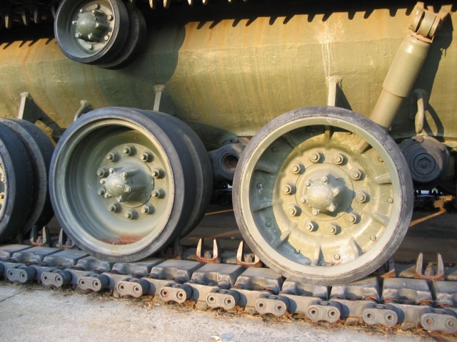
The forged aluminum wheel on the right is easily contrasted with the steel wheel on the left; reinforcing ribs easily differentiate the aluminum wheels. The mounting for the road wheel swing arms are obvious, as are the bump stops behind each road wheel.
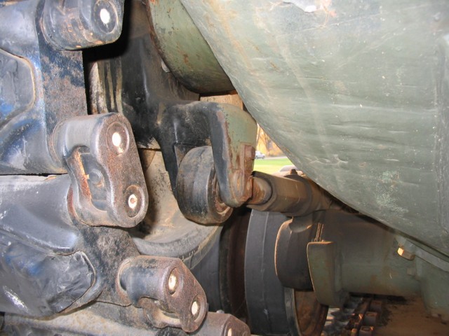
The linkage for the adjustable compensating idler wheel is shown here. The rubber pads on the T142 track are secured by a bolt that goes through the track block.
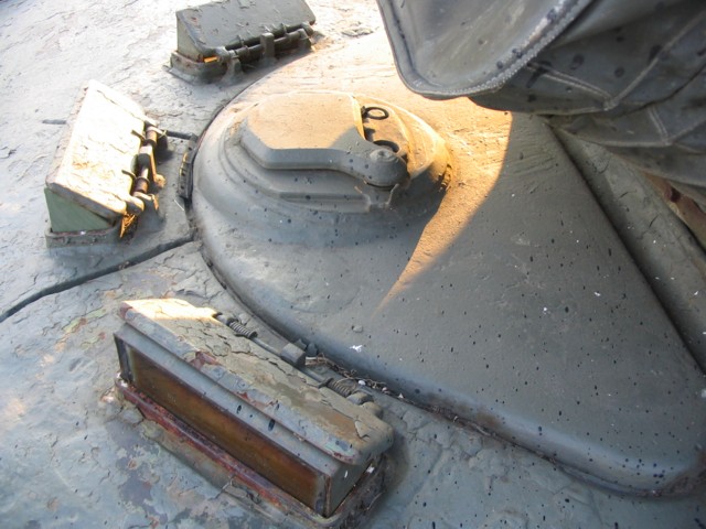
This view of the driver's hatch shows the mounts for the periscopes around his position, as well as for the night vision device in the hatch door itself. This hatch had originally been designed for the infrared periscope M24, but was then modified to accept the AN/VVS-2 passive viewer.
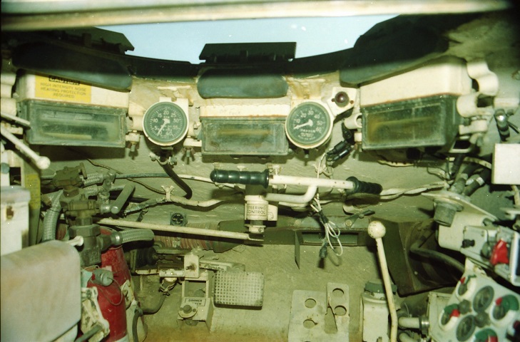
The interior of the driver's position is shown here. The steering T-bar is pivoted to the right. In this position, the tank would turn to the left while moving forward, and to the right while in reverse. The red warning light above and to the right of the speedometer alerted the driver to high engine or transmission oil temperature, or low transmission oil pressure. (Photo by Richard S. Eshleman.)
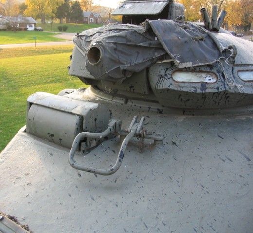
The right side of the turret was home to the commander's cupola and the gunner's periscope sight. The round aperture for the commander's M85 machine gun is visible in the cupola's front, and a periscope guard is present on top of the cupola. From the turret mounting surface, the cupola is 21.56" (54.76cm) tall to the periscope guard and 16.57" (42.09cm) without the periscope guard. Its inner diameter was 34" (86cm) and its total diameter was 52.25" (132.7cm). Lengths with and without the machine gun were 96" (240cm) and 64" (160cm), respectively. With the M85 machine gun and 180 rounds of ammunition, the cupola weighed 2,439lb (1,106kg). Mounted just beside the gunner's periscope is an interrupter bar that, when swung to the vertical position, was meant to prevent the commander's machine gun from firing down onto the gun shield-mounted searchlight. The rounded top to the gunner's periscope guard indicates that this tank is equipped with the AN/VSG-2 tank thermal sight. Non-TTS tanks (like the M60 above) had a flat-topped periscope guard.
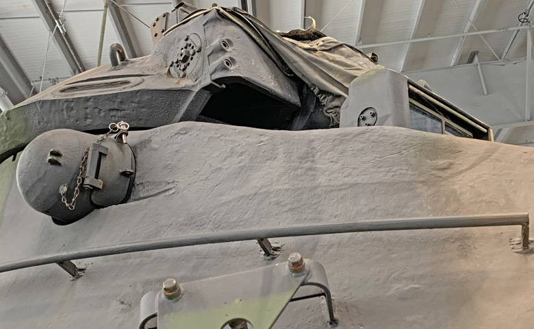
With the canvas dust cover bunched out of the way, the aperture in the cupola for the ejection of empty .50cal cases can be seen. The gunner's periscope guard has been opened. The laser rangefinder occupied the right-side rangefinder blister, and was protected by an armor flap when not in use. At the bottom of the image is the mounting bracket for a smoke grenade launcher assembly.
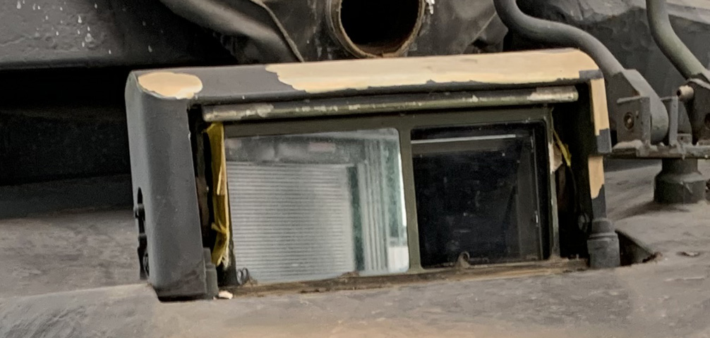
A close-up of the open gunner's primary sight housing is provided here. The image visible is a reflection of a garage door on the opposite side of the building.
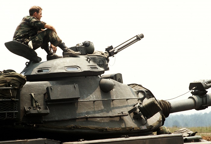
The shape and thickness of the commander's cupola door can be seen in this image. This tank from the 1ST Battalion, 108th Armor, 48th Brigade, Georgia National Guard was taking part in an annual training exercise, hence the MILES sensors on the turret and pyrotechnics mounted on the main gun's bore evacuator. (Picture taken 15 Jul 1983 by Long; available from the National Archives.)
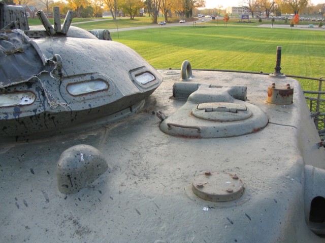
The loader had his own hatch in the left side of the turret roof, and an M37 periscope was provided in his hatch door. The flexible base of the crosswind sensor is visible on the rear of the turret, and hidden from view behind the commander's cupola is a turret ventilator. The left-side rangefinder blister is empty since the laser rangefinder only occupied the opposite blister. Note that the xenon searchlight receptacle has been capped on this tank, since it was no longer necessary.
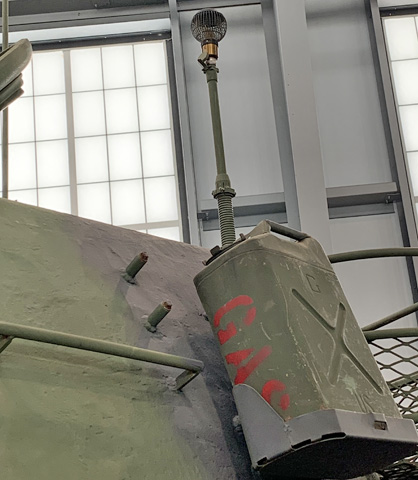
The crosswind sensor is mounted on this tank.
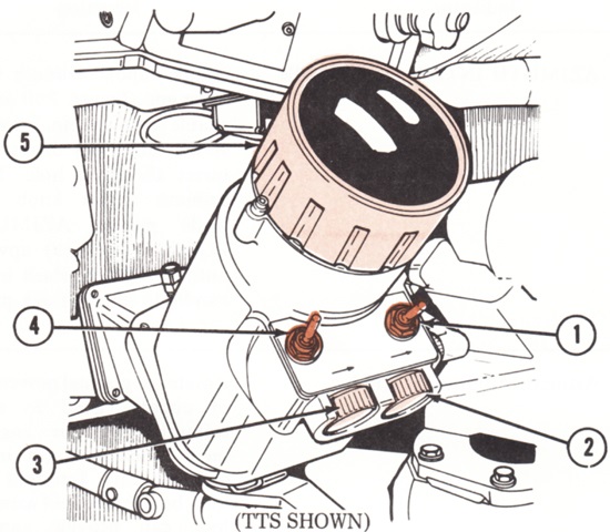
The commander's controls and indicators for the tank thermal sight are labeled in this and the next sketches. 1. Gunner/CMDR switch [determined if the gunner or commander controlled the display contrast, brightness, and polarity]. 2. Brightness knob. 3. Contrast knob. 4. Polarity switch. 5. Thermal channel eyepiece. (Picture from TM 9-2350-253-10 C12.)
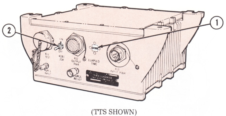
1. Elapsed time meter [recorded the number of hours the TTS had been on]. 2. 4CB1 switch (circuit breaker) [controlled power to the TTS system]. (Picture from TM 9-2350-253-10 C12.)
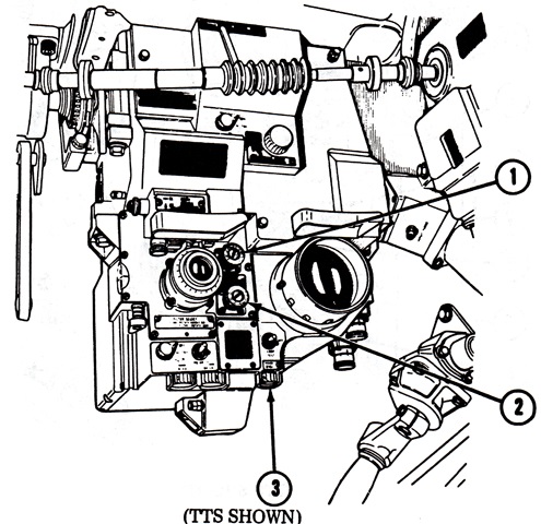
The gunner's station in a TTS tank is labeled. 1. Day channel boresight elevation knob. 2. Day channel boresighting azimuth knob. 3. Reticle and thermal channel status indicator brightness control. (Picture from TM 9-2350-253-10 C12.)
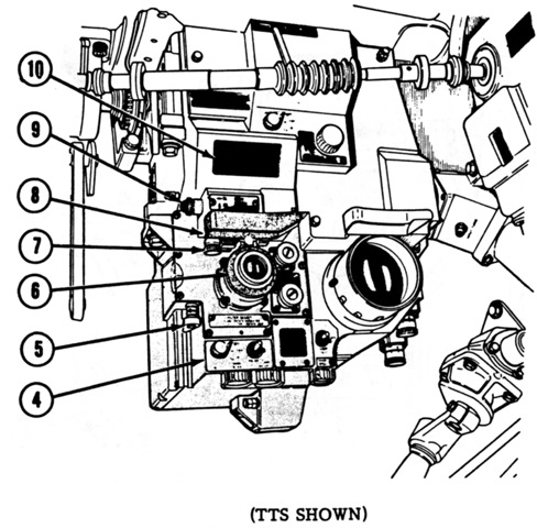
4. Daylight channel periscope. 5. Filter selector [selected between haze, red, neutral density, or clear filters for the daylight 8x channel]. 6. Daylight channel diopter ring. 7. Unity power reticle boresight azimuth knob. 8. Headrest locking lever. 9. Unity reticle boresight elevation knob. 10. Unity power window. (Picture from TM 9-2350-253-10 C12.)
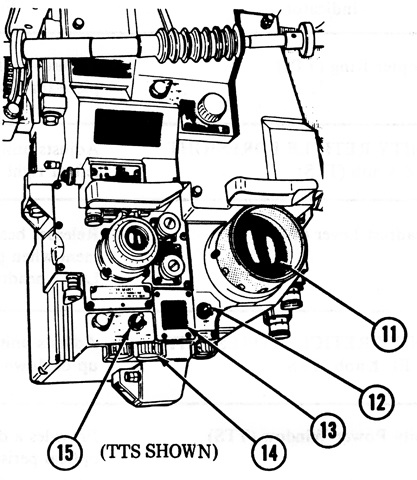
11. Thermal channel eyepiece. 12. Sys Test, Off, Lamp Test (BITE) switch [Sys Test: tested TTS assemblies; Off: de-energized Sys Test and Lamp Test, and returned to center (Off) automatically; Lamp Test: tested lamps in built-in test equipment (BITE) display]. 13. BITE display [displayed system status/malfunctions. With Mode switch in Stby or On positions: Cool illuminated until thermal detector cooled to operating temperature (within 15 minutes). With BITE switch held in Sys Test position: Cable indicated a loose or defective cable; Pwr Conv indicated a power converter unit malfunction; Head Assy indicated a head assembly display malfunction; Gnr Dspl indicated a gunner's display malfunction; Cmdr Dspl indicated a commander's display malfunction]. 14. Thermal display brightness control; just to the left is the thermal display contrast control. 15. Polarity switch. To the left of the polarity switch is the Mode switch, which controlled TTS power in three positions: Stby provided power to the cooler circuit; On activated all TTS power; Off turned all TTS power off except for the daylight channel and unity power reticles, which would be on if the Computer Power switch was on. (Picture from TM 9-2350-253-10 C12.)
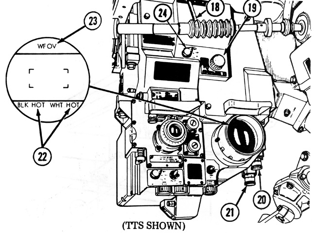
The thermal's wide field of view reticle is sketched in the inset. 18. Thermal channel field of view selector [wide or narrow]. 19. Thermal channel range focus control. 20. Thermal channel boresight azimuth knob. 21. Thermal channel boresight elevation knob. 22. Blk Hot/Wht Hot indicator [showed position of polarity switch]. 23. WFOV indicator [showed when wide field of view was selected]. 24. Thermal filter knob. (Picture from TM 9-2350-253-10 C12.)
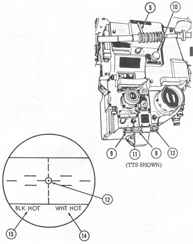
The narrow field of view thermal reticle is displayed at the lower left. 5. Thermal channel field of view selector. 8. Thermal display brightness control. 9. Thermal display contrast control. 10. Thermal channel range focus. 11. Polarity switch. 12. Narrow field of view reticle. 13. Reticle brightness control. 14. White hot indicator. 15. Black hot indicator. (Picture from TM 9-2350-253-10 C12.)
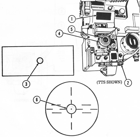
The TTS daylight channel reticles are drawn in this picture. 1. Unity power window. 2. Reticle brightness control. 3. Unity power reticle. 4. Diopter ring. 5. Daylight channel eyepiece. 6. Daylight channel reticle. (Picture from TM 9-2350-253-10 C12.)
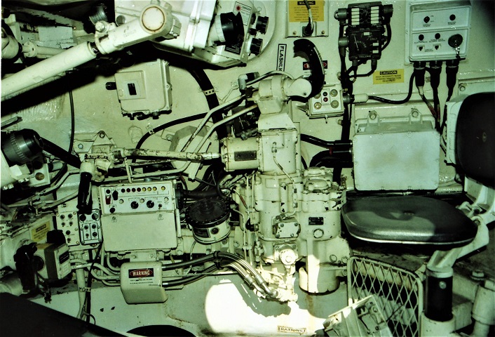
The right side of the turret is detailed in this picture. The commander's seat is elevated to the right, and the gunner's position is directly to the front and below. The commander's black control handle sits atop the turret traverse gearbox assembly; the commander's control handle was connected to the gunner's control assembly by the two rods: the upper elevation rod and lower traverse rod. The unmarked white box directly behind the gearbox assembly on the turret wall is the electronics controller unit. Directly behind his control handle on the turret wall with is his ammunition select box. The black box on the turret wall above and to the right of the ammunition select box is the commander's communication control box, and the networks box for the cupola power switch and circuit breakers for the stabilization electronics and power pack blower motor is to the right of this. The laser rangefinder can be seen near the top of the image; the upper black knob was for adjusting deflection while the lower knob was for adjusting elevation. In front of the turret traverse gearbox is the gunner's azimuth indicator, with his large control unit and smaller stabilization control box and gun control boxes going forward along the turret wall. Above the stabilization control box is the turret hand traverse drive; the shaft from this handle connects to the turret gearbox assembly via the no-bak assembly, which prevents the rotation of the hand traversing drive handle when the turret is using hydraulic power, or when the turret rotates due to being on a slope or when the gun tube strikes an obstacle. The gunner's control handles can be seen on the lower left. The tank thermal sight is not mounted, but the commander's extension would snake along the turret wall above where the rods exiting the front of his override handle have been bent downward. The gunner's telescope remains, however. (Photo by Richard S. Eshleman.)
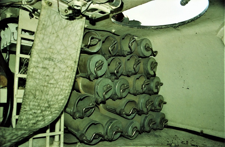
The 105mm ammunition stowage in the turret bustle is shown here. (Photo by Richard S. Eshleman.)
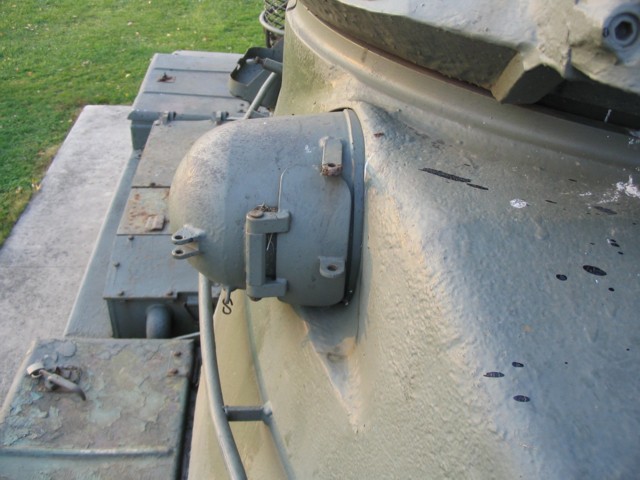
The protective flap on this blister would open when the laser rangefinder was in use. The rangefinder could detect targets from 200m to 4700m and had a maximum lasing rate of 3 per minute, or 6 per minute for 2 minutes followed by a 3-minute cooling period. An armored fender-mounted air cleaner is visible behind the rangefinder blister between the fender stowage boxes.
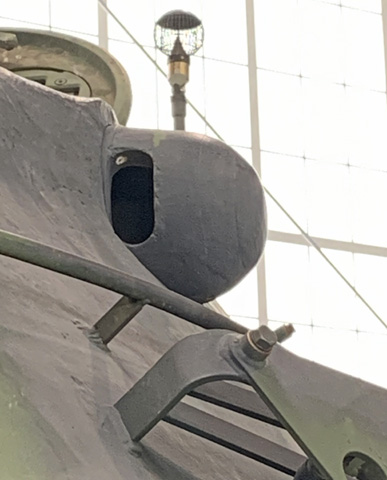
The rangefinder blister on the turret's left side remained, even though it was empty.
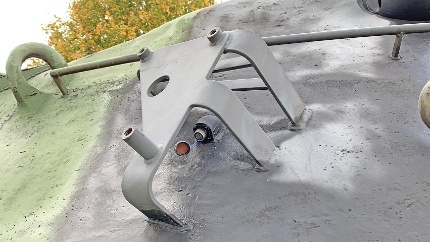
The mount for the left-side smoke grenade launcher is shown here, absent the launcher itself. The power receptacle cap is unscrewed.
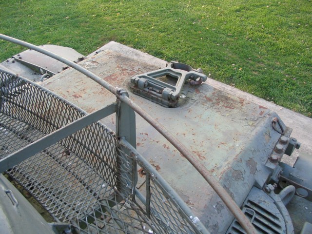
The travel lock for the tank's 105mm gun was placed on the covering for the insulated exhaust tunnel. The tunnel was lined on both sides by air intake louvres for the engine. A wire stowage basket is present on the rear of the turret.
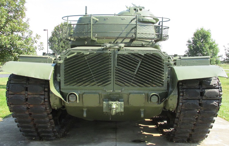
The exhaust grille doors are highlighted here, and the shape of the armor below these can be contrasted with the M60A2 with the CBSS. The square in the right-side door is for mounting a deep-water fording exhaust stack, and the two square panels under the grille doors were for access to the tank's transmission.
