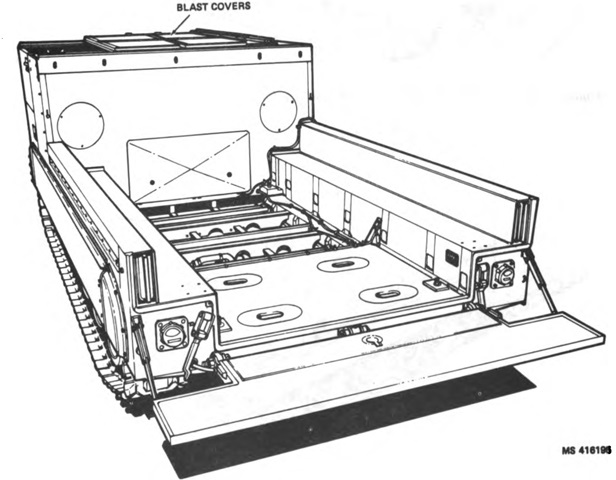
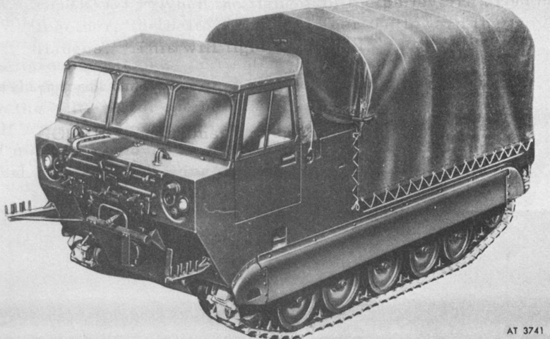
Guided Missile Equipment Carrier M730.
The M730 is drawn here without the launching station M54 in the cargo area. Modifications made from the M548 on which it was based included the fitting of blast covers to protect from missile exhaust, lower side walls and tailgate, adjustment to the cargo cover to comply with Berne gauge clearance requirements, the addition of four structural tie points for mounting the launching station, changing of the personnel heater ducting so that only the cab was heated, and increasing the cab seating to accommodate the five-man crew. (Picture from TM 9-1425-1585-10-1.)
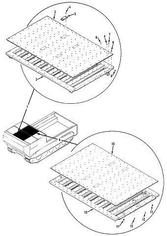
The integration support structure mounted in the cargo compartment was divided into four sections. The forward section housed the batteries, power distribution equipment, auxiliary receiver, elevator motor, missile air purification assembly, and the crew's equipment and tools. In the section behind this was the mount elevator subsystem. To the rear of this section was the space for the main power unit (MPU), a battery heater, fuel pump, and fuel safety valve. The rear section was itself partitioned into two sections: to the left was a compartment for the stowage of missile fins and wings, and to the right was the missile air compressor, communications equipment, the MPU control equipment, and the master control panel. (Picture from TM 9-1425-1585-10-1.)
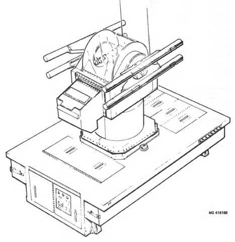
The guided missile launching station was composed of a turret, or mount, and a supporting base structure. The turret was equipped with an identification friend or foe (IFF) subsystem, and also allowed for the aiming and firing of the missiles. The base structure provided mechanical support for the turret as well as stowage for auxiliary equipment, missile reloads, and crew equipment and tools. The station was independent of the carrier, and it could also be emplaced on the ground or other carrier such as a trailer or rail car. (Picture from TM 9-1425-1585-10-1.)
When combined with the launching station, the complete system was designated as the guided missile system, intercept-aerial M48. The launching station M54A1 is mounted is this sketch, yielding the M48A1. The base of the mount was completely enclosed to provide environmental protection to the equipment it housed, and the top surface had an ablative coating applied to both protect against missile exhaust and provide the crew with a standing or walking surface. (Picture from TM 9-1425-1585-10-1.)
With the canvas cover installed, the racks on the front of the vehicle for stowing the support bows can be seen. (Picture from TM 43-0001-31.)
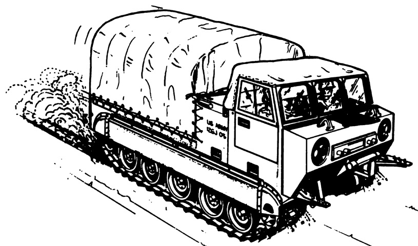
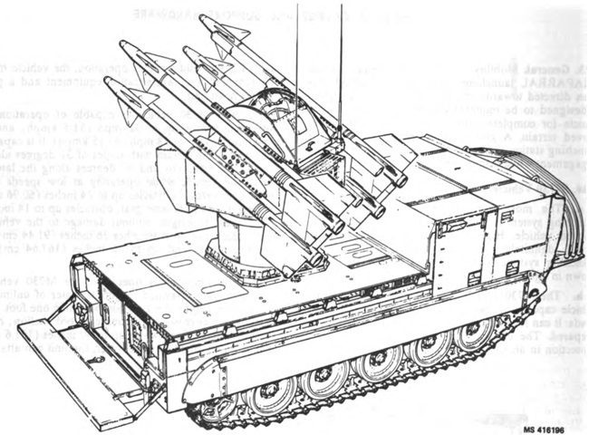
The turret was able to be retracted for travel, and the time for erection or retraction was less than 30 seconds. When the cargo cover was mounted, the radio antennas could be attached to the left side of the carrier via a jumper cable. (Picture from TM 9-1425-1585-10-1.)
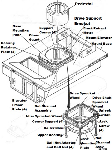
The mount was supported at each corner by a low-friction screw jack. To raise and lower the mount, the jacks were simultaneously actuated by an electrically-driven endless roller chain. (Picture from TM 9-1425-1585-10-1.)
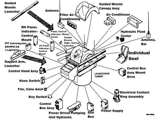
Equipment found in the launching turret is shown in this drawing. The air conditioner, azimuth and elevation drive units, hydraulic power supply heat exchanger, and equipment cooling blower and dust filter were behind the internal bulkhead, and could be accessed via an external rear door or a removable structure above the gunner's seat. The hydraulic power supply, electronics power supply, mount drive electronics, missile sequence and control electronics, electrical slipring, and pneumatic swivel joint were all attached to a structure that was integral with the turret floor. All equipment under the gunner's floor was in the ring base and rotated with it. Two opposing doors in the ring base wall provided access to these assemblies. (Picture from TM 9-1425-1585-10-1.)
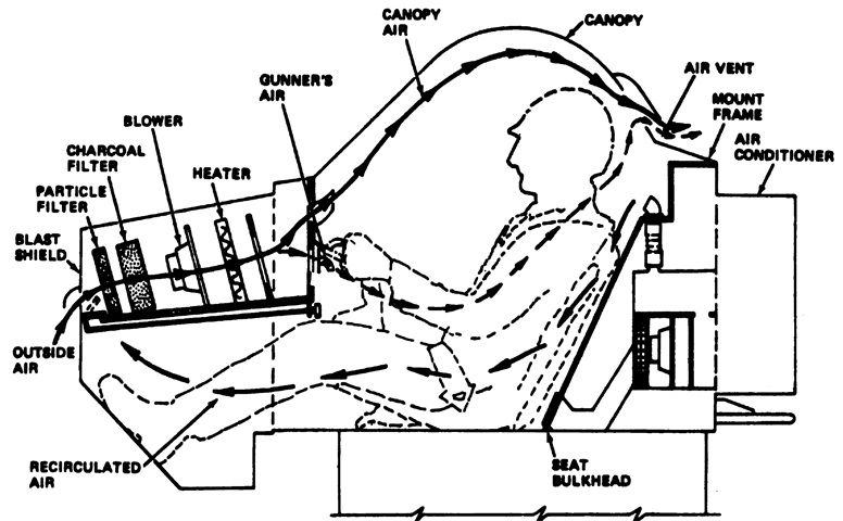
The gunner is shown in this illustration of the turret's environmental control subsystem. A three-speed blower activated whenever the mount power was on, and all new or recirculated air was passed through both a particle and charcoal filter. This also maintained a slight positive pressure to prevent the ingress of toxic missile exhaust. Air was vented out through a flapper valve at the compartment rear. (Picture from TM 9-1425-1585-10-1.)
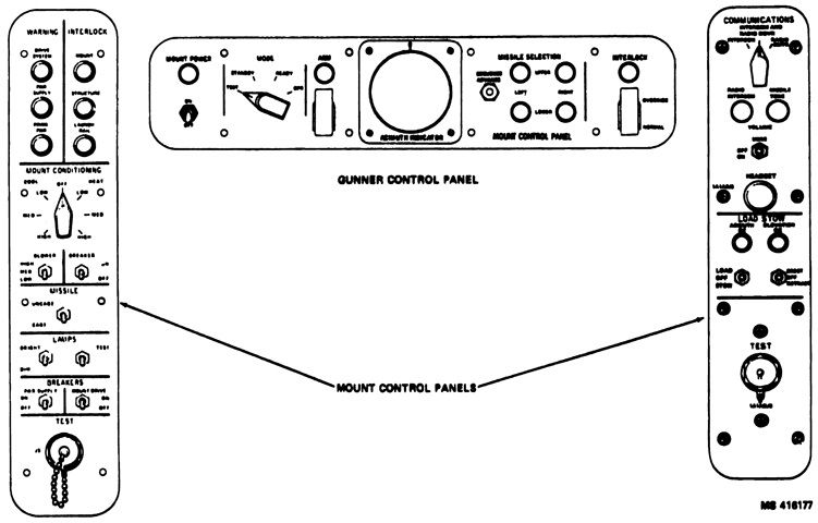
The gunner had three panels in his compartment. The right panel contained controls for the communication subsystem and mount load/stow functions. The gunner's headset could be plugged into the panel, and at the bottom was a test connector that could also serve as a connection for a kneeswitch to key the radio microphone without requiring the use of the gunner's hands.
The left panel contained warning lights for the drive subsystem, the regulated power supply, and the prime power subsystem. To the right of these lights were lights that activated when firing interlocks were active, including open access doors or hatches, unremoved firing pins, etc. Controls for the mount air conditioner were below the lights, and the missile cage/uncage switch was below these controls. This allowed the gunner to cage or uncage the seeker of a selected missile while in the TEST mode. Controls for the panel lamps were under this, followed by circuit breakers and another test connector.
The center panel contained the mount power switch, mode switch, azimuth indicator, missile selector, and interlock override switch. (Picture from TM 9-1425-1585-10-1.)
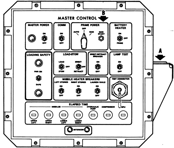
The master control panel was located in the rear of the integration support structure. This featured controls for the master power, communications, battery heater, prime power system, loading safety that deactivated power to the launching rails, load/stow and erect/retract controls that were duplicated from the gunner's panel, circuit breakers, and indicator lamp testing. It also tracked the elapsed time that each of the missiles on the launch rails had power applied to the seeker gyro as well as the cumulative running time of the hydraulic pumping unit, air compressor, and the engine-generator set. (Picture from TM 9-1425-1585-10-1.)
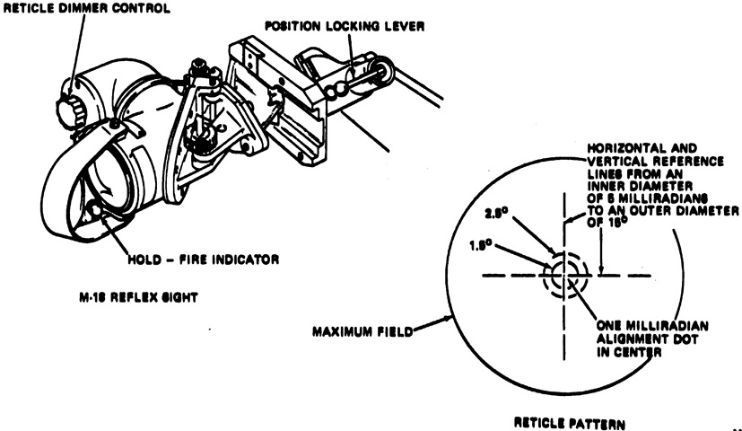
The reflex sight M18 was a unity power unit that was able to be used due to the large field of view of the missiles. While the goal was to track the target aircraft with the center dot, gunners of average skill were able to track typical targets within the center half of the inner ring. (Picture from TM 9-1425-1585-10-1.)
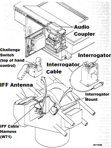
The IFF subsystem recognized aircraft fitted with Mode 3 and 4 transponders as friendly. The gunner would press the challenge switch on his control, and a coded signal would be sent to the aircraft from the IFF antenna. The aircraft's transponder would automatically generate and send a response, which was routed from the antenna to the AN/PPX-3A interrogator. In response to an aircraft with a Mode 3 transponder, the system would generate a 1.5-second beep in the gunner's headset. A response from a Mode 4 transponder would generate a half-second beep, half a second of silence, and another half-second beep. No response would generate a series of beeps. No beeps would be generated in the case of a system failure. (Picture from TM 9-1425-1585-10-1.)
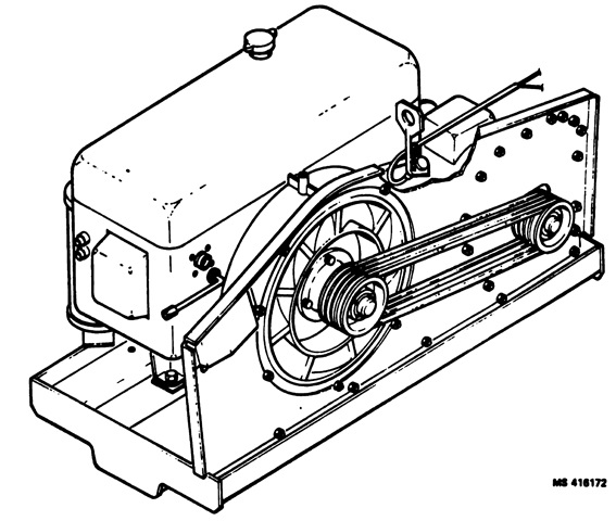
The main power unit was a 10-horsepower 2-cylinder gasoline engine and a belt-driven 28Vdc 300 ampere generator that could also serve as the starter for the engine. This unit provided power for the prime power subsystem that was stored in four 12-volt 100 ampere-hour lead-acid batteries connected in series-parallel. The prime power subsystem provided power for equipment such as rotary equipment, heaters, and the electronic power supply. A regulated power supply provided power for the electronic circuits of the fire unit and missiles. (Picture from TM 9-1425-1585-10-1.)
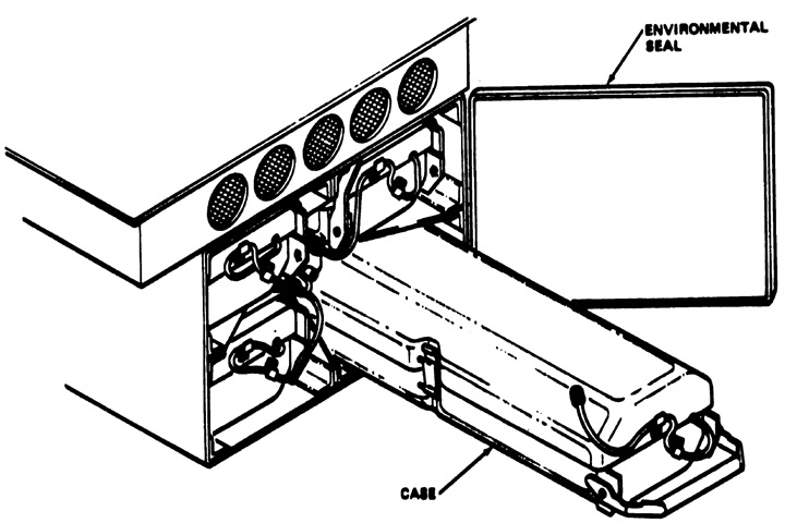
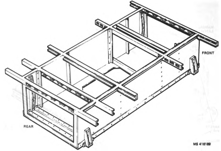
The deck of the integration support structure extended beyond the sides of its frame. These overhangs were used to attach sheet metal bins that allowed the stowage of four protective cases, each of which contained a missile body without fins or wings. (Picture from TM 9-1425-1585-10-1.)
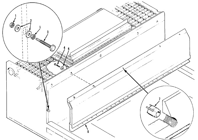
Attachments for the blast shield for the engine compartment are diagrammed in this sketch. (Picture from TM 9-1450-585-34P.)
Blast covers were also able to be mounted on the top of the engine compartment and cab. (Picture from TM 9-1450-585-34P.)
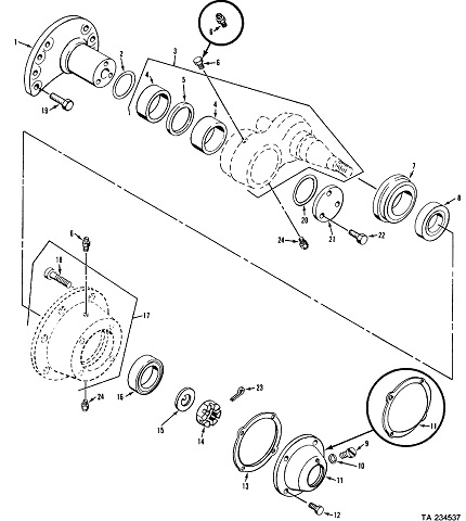
An exploded view of the idler wheel mounting found on early carriers is shown here. (Picture from TM 9-1450-585-34P.)
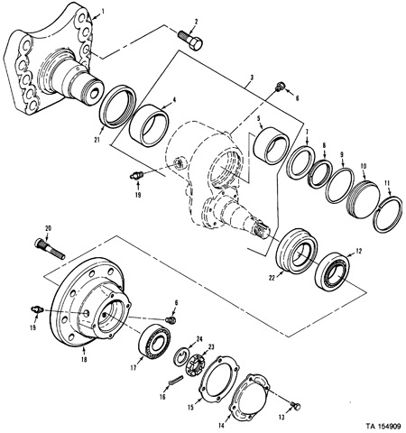
Modifications to the idler wheel produced this design in later carriers. (Picture from TM 9-1450-585-34P.)
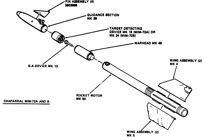
A diagram of the MIM-72A and B is provided here. These were 114.5" x 5" (290.8cm x 13cm) when unpackaged and weighed 190lb (86kg). The S-A device MK13 prevented detonation of the warhead during handling, assembly, and the initial portion of flight. A window at the rear indicated "S" for safe and "A" for armed. The MK50 motor was 72.4" (184cm) long and 5" (13cm) in diameter; weighed 97lb (44kg); and was composed of a steel case with an igniter at the forward end, a hollow star-shaped cylinder filled with 60.3lb (27.4kg) of propellant. Both TDDs MK15 and MK24 used a MK70 thermal battery to provide independent power supply. The battery was activated by an electrical signal when the missile was launched. (Picture from TM 9-1425-1585-10-1.)
The guidance section MK28 weighed 31lb (14kg), and was 24.3" (61.7cm) long by 5" (13cm) in diameter. The fins were attached to a rocker arm by a quick-attach latching mechanism. On the MIM-72A/B, pins in two fins were engaged by fin retainers in order to be held in the fore/aft position. Torque applied by the servo early in flight would force the pins out of the retainers. (Picture from TM 9-1425-1585-10-1.)
The three major sections of the guidance section were the seeker section for detecting the target's infrared radiation and sensing directional changes in the sightline to the target, an electronics section for converting the gathered target information into a seeker guidance signal and guidance command signal, and a servo section that converted the guidance signals into angular deflection of the control fins. Prior to launch, external power was transferred to the guidance section via an umbilical cable which was disconnected flush with the missile surface at launch. (Picture from TM 9-1425-1585-10-1.)
An exploded view of the infrared seeker section is drawn here. 1. Dome, housing. 2. Screw, self-locking socket. 3. Gyro, optical. 4. Post. 5. Barrier guide. 6. Cover, desiccant. 7. Screw, machine. 8. Packing, preformed. 9. Valve, relief. 10. Barrier, guide. 11. Cover, desiccant. 12. Coil-head, potted. 13. Clamp, rim, clenching. 14. Screw, cap, socket. 15. Pin, spring. 16. Ring, aligning. 17. Ring, externally. [sic] 18. Screw, machine. 19. Washer, lock. 20. Washer, flat. 21. Detector, missile. 22. Shim. 23. Packing, preformed. 24. Packing, preformed. (Picture from TM 9-1410-585-24P.)
The gyro was in the head-coil assembly. Active coils (four gyro drive coil pairs, two precession coils, and the supercaging coil) exerted electromagnetic forces on the gyro magnet to rotate and tilt the optical system. Passive coils (four saturable reactors, four reference coils, the caging coil, the caging cancellation coil, and supercaging cancellation coil) were acted upon by the gyro magnet and fed information to the electronic circuits. The gyro drive coils spun the gyro at the appropriate rotational speed. Precession coils precessed the gyro to the target sightline during tracking. The reference coils were out of phase by 90° and represented the missile's two major coordinate planes. The current that drove the precession coils was compared to the reference signals to obtain the signals that drove the aerodynamic control surfaces. The caging coil indicated the magnitude and direction that the gyro's axis differed from that of the missile. If the gyro and missile axes coincided, the gyro magnet did not affect the caging coil. Cancellation coils reduced the inductive coupling between active coils and the error-sensing caging coil. The saturable reactors were part of the gyro motor speed control loop. (Picture from TM 9-1425-1585-10-1.)
The servo section converted steering commands received from the electronics section into applied torques to the fins. Two sets of push-pull solenoids were used to control the piston valves. The pistons acted in pairs, up-down and right-left, so that as the current in one piston solenoid valve (e.g., for a right turn) was increased, the current in the opposite valve (for a left turn) was reduced. The resulting differential piston pressure rotated a rocker arm to which a pair of fins was mounted until the torque on the fins from the airstream matched the torque being imparted by the servo. Pneumatic power for the pistons was via a slow-burning solid propellant grain contained in a canister attached to the servo block. The propellant was ignited electrically upon launch. Seen on the right, the MIM-72C/E also featured pendulum potentiometers on the rocker arms to provide feedback for accurate fin control at low torque command. (Picture from TM 9-1425-1585-10-1.)
Roll rate control was provided by rollerons on two of the rear wings. The rollerons were gyro-activated automatic trim tabs: airflow spun the steel wheel that provided gyro forces to the rolleron trim tab; these forces deflected the trim tab into the airstream when the missile rolled. Flutter was prevented by a rolleron damper assembly that hinged the rolleron to the wing and provided a damping and stabilization action for the rolleron. (Picture from TM 9-1425-1585-10-1.)
The MK48 warhead enclosed a continuous-rod destructive device with ~6.1lb (2.8kg) of PBXN-3 explosive shaped into a bowtie configuration. The warhead was 5" (13cm) in diameter, 12.16" (30.89cm) long, and weighed a total of 25.25lb (11.45kg). The cap was the housing for the S-A device, and the aluminum case was the main structural element. The rod bundle fit over the aluminum case and under the stress skin. (Picture from TM 9-1425-1585-10-1.)
The MIM-72C and MIM-72E were dimensionally identical to the earlier versions. (Picture from TM 9-1425-1585-10-1.)
Unlike the -A/B missiles, the fin restraint on the MIM-72C/E was maintained by the servo itself instead of separate fin retainers. (Picture from TM 9-1425-1585-10-1.)
The warhead on the -C/E missiles was changed to the M250 blast/fragmentation type, which was aluminum (except for the fragments) and cylindrical. It was 12.16" (30.89cm) long, 5" (13cm) in diameter, and weighed ~25lb (~11kg). It contained ~6.6lb (~3.0kg) of 75/25 OCTOL/TNT. (Picture from TM 9-1425-1585-10-1.)
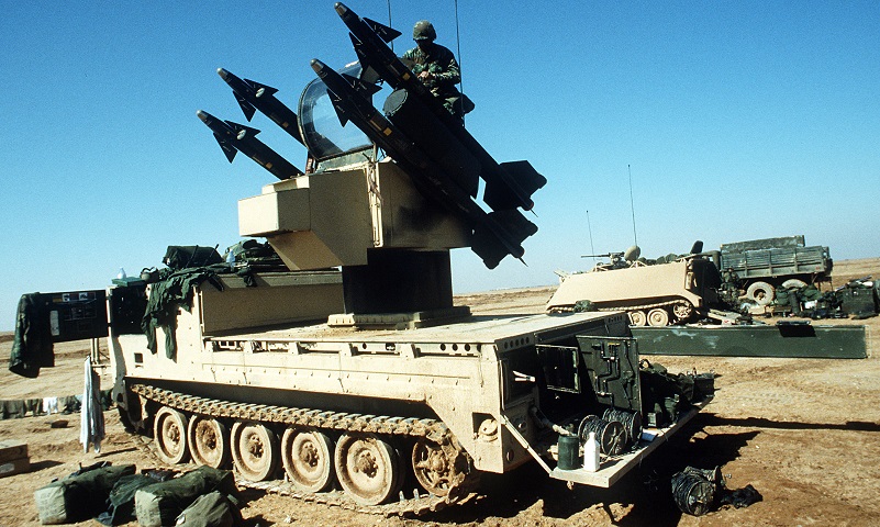
The missile launch control station has been elevated for action on this vehicle, and gunner is seen entering or leaving his station. Bows for supporting the cover that protects the missile launcher pallet when not in use are stowed on the vehicle's bow. (Picture available from the National Archives.)
This vehicle has the cab cover installed. This would need to be removed before the vehicle was ready to fire. (Picture taken by SSG Loder; available from the National Archives.)
The carrier is shown here with the missile system dismounted. (Picture from TM 55-2350-224-14.)
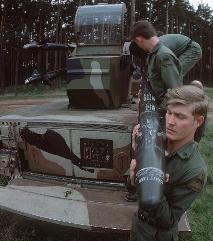
Missiles are being loaded onto their launch rails in this picture. The master control panel can be seen on the rear of the integration support structure. (Picture taken on 1 Oct 1977; available from the National Archives.)
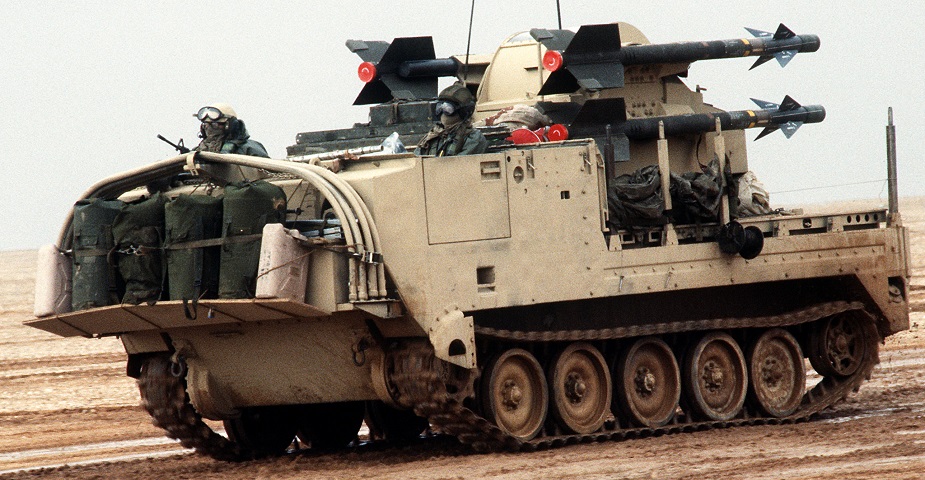
Extra stowage is mounted on the platform under the cargo compartment bows on this vehicle, and the crewmen visible have protected their faces against the elements with scarves. The driver's door can be seen, and the circle with the horizontal handle directly behind the door was for external activation of the vehicle's fire extinguishers. The small hole above and forward of the fire extinguisher handle was the aft bilge pump outlet, and the fuel filler cap can be seen in the recess behind the idler wheel. The missile launcher has been lowered for travel. (Picture available from the National Archives.)
Rear stowage is visible on this I-Chap. The FLIR pod for night operations can be seen mounted between the two missiles nearest the camera, and the driver's door is open. Note that neither the interior of the cab nor the missile launcher pedestal has been repainted from their original olive drab. (Picture available from the National Archives.)
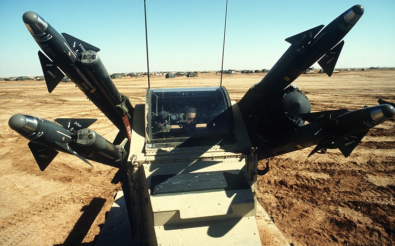
The gunner's position is manned in this vehicle, and the FLIR pod can be seen to the gunner's left between the missiles. (Picture available from the National Archives.)
