Medium Recovery Vehicle M88.
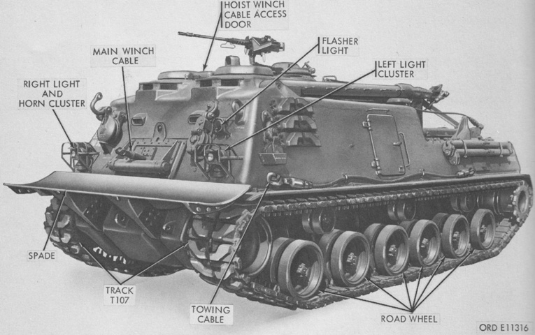
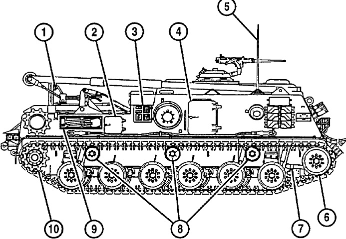
Various components of the vehicle are illustrated in this left-front view. (Picture from TM 9-2320-222-10.)
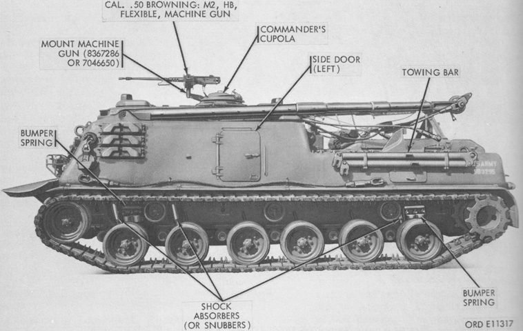
The left side of the vehicle is diagrammed in this image. (Picture from TM 9-2320-222-10.)
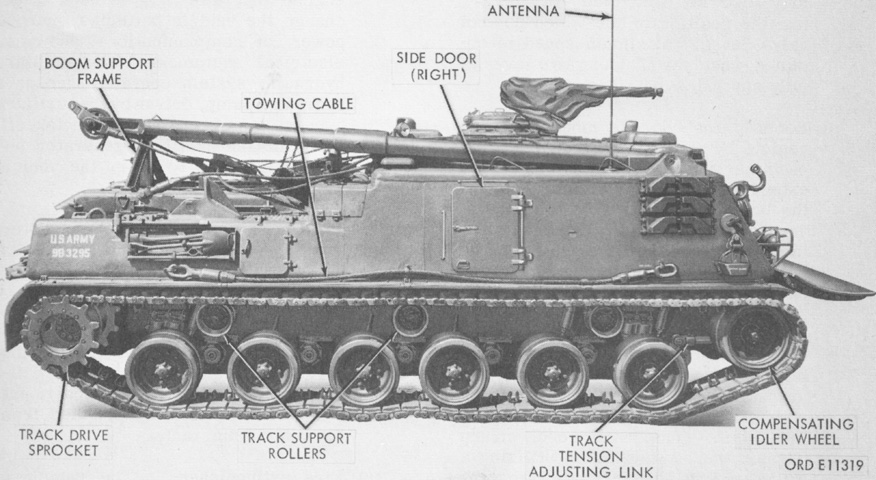
The right side of the vehicle is diagrammed in this image. (Picture from TM 9-2320-222-10.)
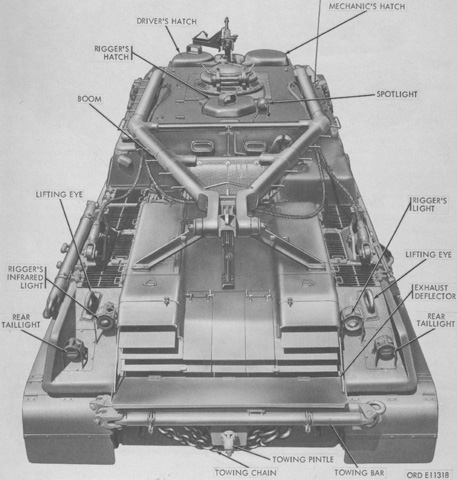
The rear of the vehicle is shown here. (Picture from TM 9-2320-222-10.)
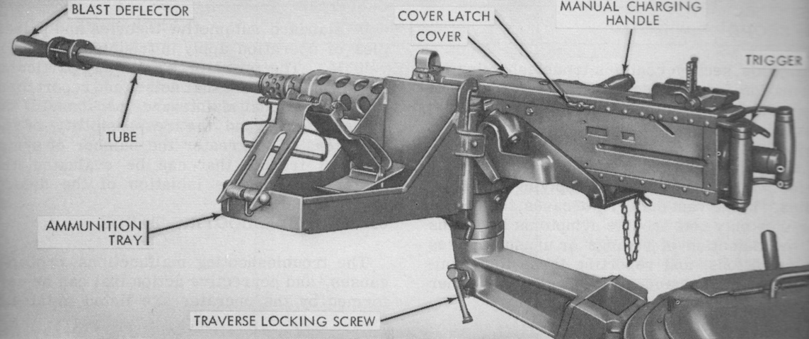
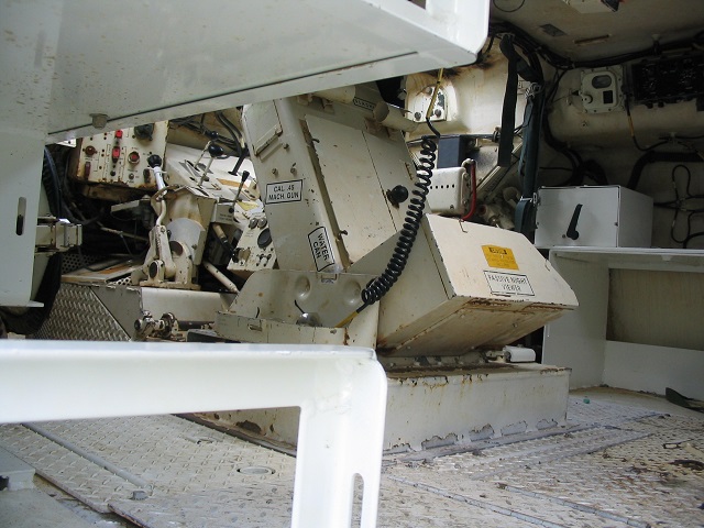
The machine gun mount on the commander's cupola is shown here. (Picture from TM 9-2320-222-10.)
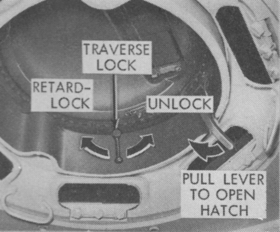
Interior controls for the commander's cupola are labeled in this image. (Picture from TM 9-2320-222-10.)
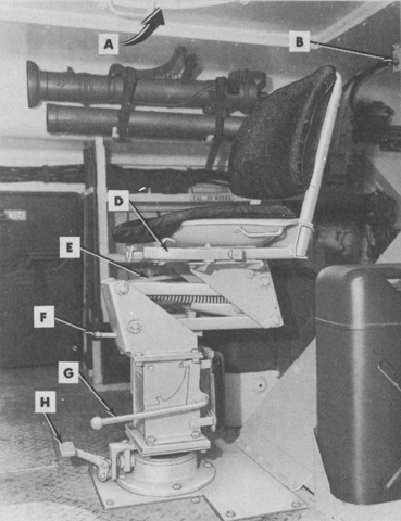
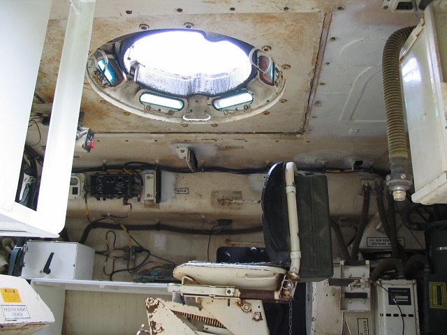
The commander's position is shown here. Note the 3.5" rocket launcher stowed near the cab ceiling in the background. A. Commander's cupola. B. Blackout receiver switch and indicator light. D. Seat horizontal adjustment. E. Seat height adjustment. F. Tilt adjustment. G. Dumping handle. H. Seat rotating adjustment. (Picture from TM 9-2320-222-10.)
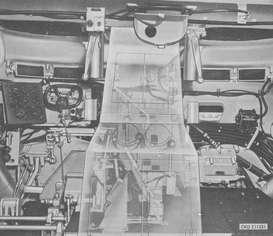
The front of the cab is depicted in this picture. The periscopes and vision blocks can be seen in front of the driver and mechanic, and their hatches in the roof are painted to match the vehicle exterior. (Picture from TM 9-2320-222-10.)
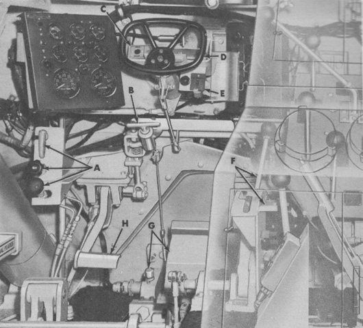
The driver's position is detailed in this image. From top to bottom, (A) points to the choke throttle control, hand throttle control, and priming pump. (B) is the spade lock control. (C) is the high beam indicator. (D) is the steering wheel with the horn switch found in the center. (E) is the blackout receiver switch. (F) is the transmission shift lever and red flasher control panel. (G) points to the dimmer switch on the left and the accelerator pedal on the right. (H) is the brake pedal. (Picture from TM 9-2320-222-10.)
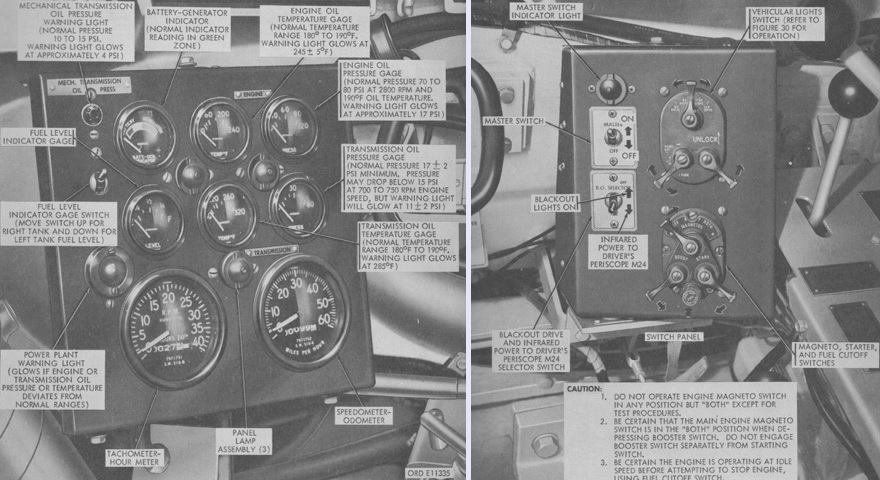
The driver's instrument and switch panels are labeled on the left and right, respectively. (Picture from TM 9-2320-222-10.)
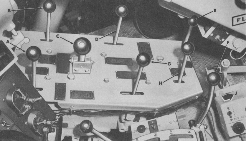
Various controls for the hydraulic system and winches are shown here. A. Boom operating lever (pushed forward moved the boom forward, released held the boom in place, pulled to the rear retracted or stowed the boom). B. System selector control handle (forward position activated the auxiliary hydraulic system; center position activated the main hydraulic system; rear position was for refueling, defueling, or hydraulic impact wrench operation). C. Spade operating lever (pushed forward to lower spade, centered to hold spade in position, pulled to the rear to raise spade). D. Main winch operating lever (pushed forward to payout cable, centered to hold, pulled to the rear to retract cable). E. Power control handle (forward on, rearward off). F. Main winch shift lever (forward low, centered neutral, rearward high). G. Hoist winch operating lever (pushed forward to payout cable, centered to hold, pulled to the rear to retract cable). H. Boom safety control handle (forward stow, rearward live). J. Hoist winch shift lever, which is out of frame (forward high, centered neutral, rearward low). (Picture from TM 9-2320-222-10.)
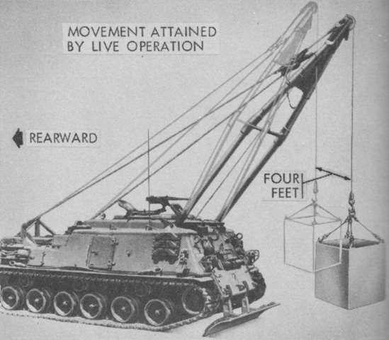
The boom is seen here deployed and in live operation, with the stayline providing support. The boom angle could be changed to move center of lift up to 4 feet (1.2m) closer to the vehicle. (Picture from TM 9-2320-222-10.)
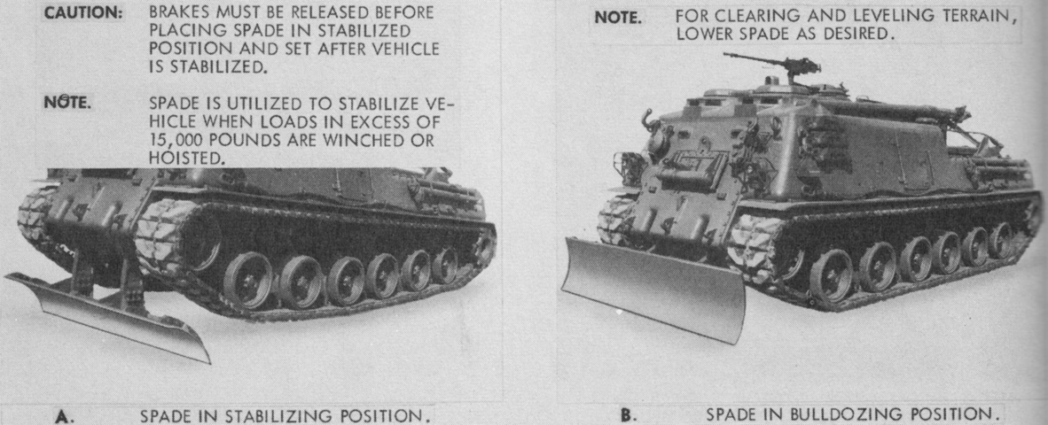
The front spade is illustrated in the stabilizing position on the left and in the bulldozing position on the right. The spade was secured when stowed by a spring-loaded safety latch on the hull exterior. This latch was released by a cable operated from the crew compartment. (Picture from TM 9-2320-222-10.)
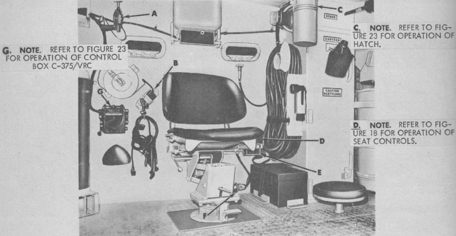
The rigger occupied the area in the cab rear. The dark-colored Stewart Warner-Southwind AAM-17 gasoline-fueled personnel heater is visible standing vertically in the cab's right rear corner beside the radio and intercom control box. To the rigger's left rear is the compartment housing the acetylene bottle. A. Spotlight control. B. Portable spotlight switch. C. Rigger's hatch control. D. Rigger's seat. E. Rigger's light and infrared light selector switch, and blackout receiver control. F. Rigger's light dimmer switch. G. Rigger's radio and intercom control box C-375/VRC. (Picture from TM 9-2320-222-10.)
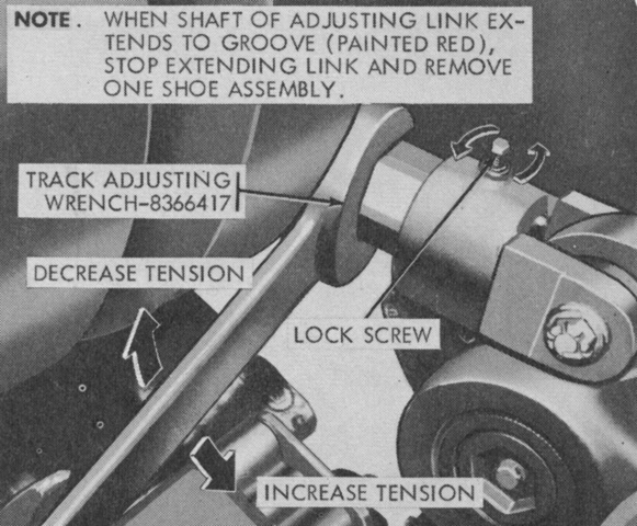
Track tension was adjusted by turning the idler wheel's track adjusting link with a large wrench after its lock screw had been loosened. (Picture from TM 9-2320-222-10.)
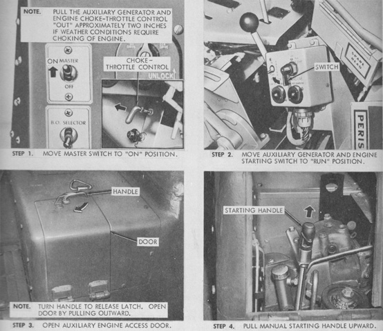
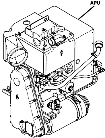
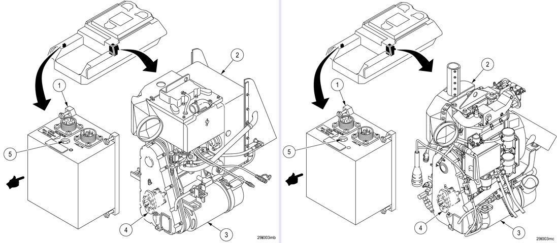
A 15hp General Motors A-41-2 1-cylinder, 4-cycle gasoline engine was used as an auxiliary generator. It was employed to charge the vehicle batteries, when using auxiliary equipment with the main engine off, or when the main engine's generator was insufficient for the required load. It could be started electrically or, as detailed in these images, manually. (Picture from TM 9-2320-222-10.)
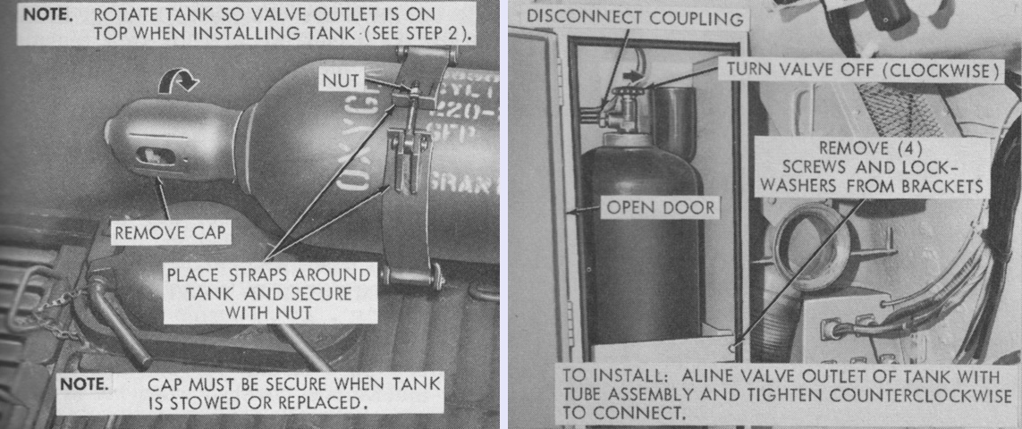
Welding equipment was carried, including oxygen and acetylene cylinders. The 220-240ft³ (6.2-6.8m³) 2,265psi (159.2kg/cm²) oxygen cylinder was secured to the hull rear just behind the cab, as seen on the left. The 125ft³ (3.54m³) 250psi (18kg/cm²) acetylene cylinder was enclosed in a cabinet at the back of the cab to the rigger's left rear. The connection was made through the cab rear wall. (Picture from TM 9-2320-222-10.)
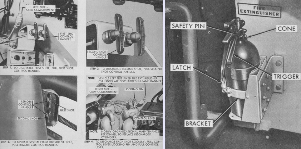
The fixed fire extinguisher system contained eight 10lb (4.5kg) CO2 cylinders that were discharged in two separate shots. Controls for the fixed extinguisher system are shown on the left. In addition, a portable 5lb (2.3kg) CO2 extinguisher was stowed next to each of the side doors, as seen on the right. Controls for the personnel heater are visible below the fire extinguisher discharge handles at the top left. The heater was plumbed into the vehicle's fuel system. (Picture from TM 9-2320-222-10.)
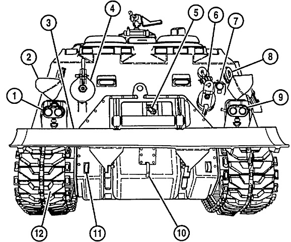
The front of the vehicle is shown here. The legend is as follows: 1. Right light and horn cluster. 2. Smoke grenade discharger (2). 3. Spade. 4. 90-ton (81.6-metric ton) snatch block. 5. Main winch cable opening. 6. 25-ton (22.7-metric ton) snatch block. 7. Flasher light. 8. Lifting eyes (2). 9. Left light cluster. 10. Towing eye. 11. Towing lug (2). 12. Track (2). (Picture from TM 9-2350-256-10 C1.)
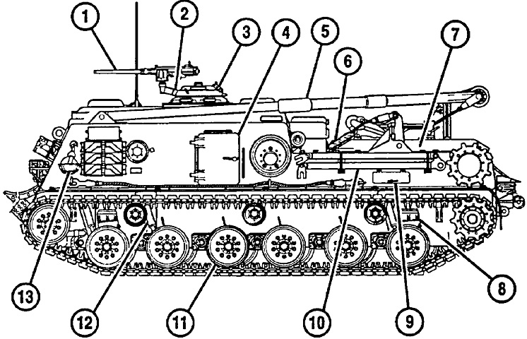
The left side of the vehicle is diagrammed in this image. A storage bin for six smoke grenades is bolted to the hull above the spare tracks near the front. 1. Cal. .50 machine gun. 2. Machine gun mount. 3. Commander's cupola. 4. Left side personnel door. 5. Boom. 6. Tarpaulin and 100-ft (30.5-m) rope. 7. Crow bar (2). 8. Bumper spring (4). 9. Left side stowage compartment door. 10. Tow bar. 11. Roadwheel (12). 12. Shock absorber (6). 13. 10-ton (9.1-metric ton) snatch block. (Picture from TM 9-2350-256-10 C1.)
The right side of the vehicle is detailed here. 1. Boom support and latch. 2. Right side stowage compartment door. 3. APU compartment door. 4. Right side personnel door. 5. Antenna. 6. Compensating idler wheel (2). 7. Track tension adjusting link (2). 8. Track support roller (6). 9. Pioneer tools. 10. Drive sprockets (2). (Picture from TM 9-2350-256-10 C1.)
The top of the vehicle is the subject of this drawing. 1. Auxiliary power slave receptacle. 2. Vise. 3. 90-ton (81.6-metric ton) snatch block. 4. Oxygen cylinder. 5. Left side air intake screen. 6. M17 periscope (7). 7. Rigger's hatch. 8. Driver's hatch. 9. AN/VVS-2(V)1A periscope, M24 periscope, or M24A1 periscope. 10 Hoist winch cable access door. 11. Mechanic's hatch. 12. Spotlight. 13. Right side air intake screen. 14. Tow cable (2). 15. Exhaust deflector. (Picture from TM 9-2350-256-10 C1.)
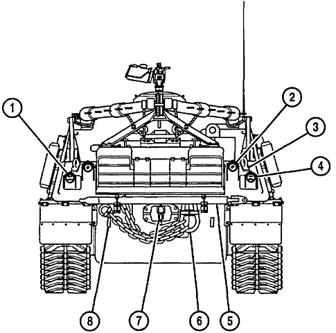
The rear of the vehicle is shown here. 1. Rear taillight. 2. Rigger's light. 3. Lifting eye. 4. B.O. [blackout] marker light. 5. Tow bar. 6. Lifting chain. 7. Towing pintle. 8. Towing lug. (Picture from TM 9-2350-256-10 C1.)
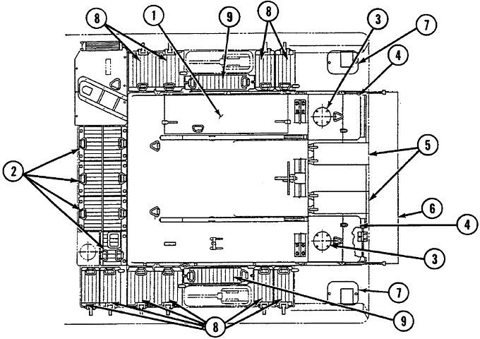
The engine deck is diagrammed here. The front of the vehicle is to the left of the drawing. 1. Right engine deck door. 2. Left- and center-front air inlet grilles. 3. Deep water fording exhaust cover plates. 4. Left and right exhaust doors. 5. Center exhaust doors. 6. Exhaust deflector. 7. Left and right hydraulic cylinder access covers. 8. Air inlet door. 9. Left and right deck air inlet doors. (Picture from TM 9-2350-256-20-1.)
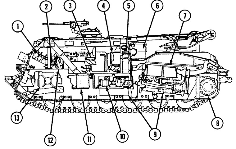
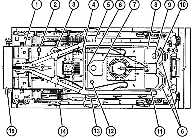
The internal components are revealed in this cross-sectional sketch. 1. Hydraulic control panel. 2. Driver's and mechanic's seats. 3. Commander's seat. 4. Rigger's seat. 5. Personnel heater. 6. APU [auxiliary power unit]. 7. Engine. 8. Cross-drive transmission. 9. Fuel tank installation. 10. Mechanical transmission and hydraulic pump assembly. 11. Hoist winch. 12. Fixed fire extinguisher system. 13. Main winch. (Picture from TM 9-2350-256-20-1.)
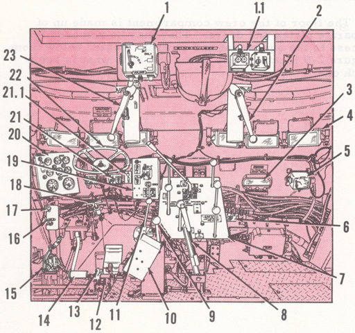
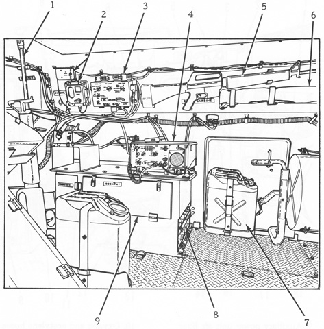
An overview of the cab front is drawn above. 1. Commander's interphone control box. 1.1. M239 smoke grenade arming switch. 2. Mechanic's hatch control. 3. Operator's and mechanic's vision blocks. 4. M17 periscope (6 shown). 5. Mechanic's interphone control box. 6. Auxiliary power unit emergency winch control valve. 7. Hydraulic controls panel. 8. Drain valve lever. 9. Main winch shift lever. 10. Auxiliary power unit. 11. Transmission shift lever. 12. Accelerator. 13. Dimmer switch. 14. Brake pedal. 15. Purge pedal. 16. Manual fuel shutoff handle. 17. Engine hand throttle. 18. Spade locking release handle. 19. Switch panel. 20. Gage panel. 21. Blackout receiver light switch and indicator light. 21.1. Vehicle exhaust smoke switch and indicator light. 22. Steering wheel. 23. Operator's hatch control. (Picture from TM 9-2350-256-10 C5.)
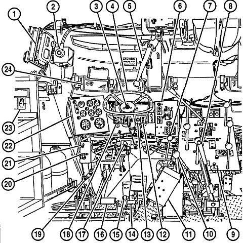
The driver's position and controls are isolated in this diagram. 1. Dome light. 2. Driver's interphone control box. 3. Horn button. 4. Steering wheel. 5. Driver's hatch control. 6. Switch panel. 7. Transmission shift lever. 8. Drain valve lever. 9. Hydraulics control panel. 10. Main winch shift lever. 11. Auxiliary power unit (APU) control box. 12. Vehicle exhaust smoke system. 13. Night viewer receiver light system. 14. Accelerator pedal. 15. Dimmer switch. 16. Brake pedal. 17. Spade locking release handle. 18. High beam indicator. 19. Purge pump handle. 20. Manual fuel shutoff handle. 21. Engine hand throttle. 22. Gage panel. 23. Personnel heater control box. 24. M17 periscope. (Picture from TM 9-2350-256-10 C1.)
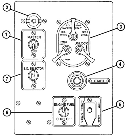
The driver's revised switch panel is drawn here. 1. Master switch. 2. Master switch indicator light. 3. Vehicular lights switch. 4. Start button. 5. Fuel pump switch. 6. Engine fuel shutoff switch. 7. Blackout selector switch. (Picture from TM 9-2350-256-10 C1.)
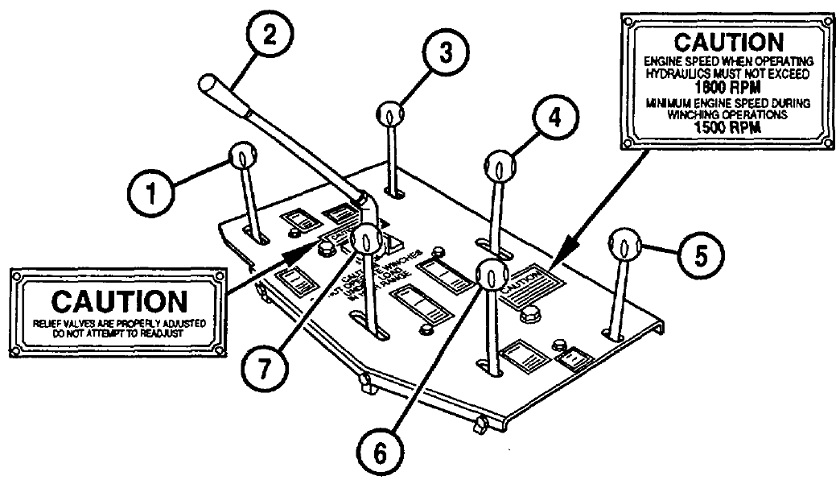
The hydraulics controls are drawn in this picture. 1. BOOM operating lever. Used to move boom up or FORWARD, HOLD, or RETRACT-STOW. Spring loaded to stay in HOLD. 2. SPADE operating lever. Used to RAISE, LOWER and HOLD spade. Spring loaded to stay in HOLD position. 3. SYSTEM SELECTOR control lever. Selects auxiliary (AUX) and MAIN hydraulic systems. REFUEL position for refuel-defuel operations. It locks in desired position. 4. MAIN WINCH operating lever. Selects PAYOUT, HOLD, AND INHAUL of main cable. Spring loaded to stay in HOLD position. 5. POWER control lever. To turn main hydraulic pump ON or OFF. 6. BOOM SAFETY control lever. Selects STOW or LIVE. Spring loaded to stay in LIVE position. 7. HOIST WINCH operation lever. Selects LOWER, HOLD, and RAISE for hoist cable. It is spring loaded to stay in HOLD position. 8. MAIN WINCH SHIFT lever. Selects LOW, NEUTRAL, or HIGH main winching speeds and locks in desired position. 9. HOIST WINCH SHIFT lever. Selects LOW, NEUTRAL, or HIGH hoisting speeds. It locks in desired position. Located right rear of driver on floor. (Picture from TM 9-2350-256-10 C1.)
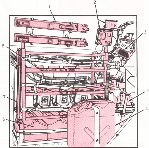
Stowage on the left side of the crew compartment is drawn above. 1. LAW rocket (2). 2. Operator's air purifier control switch and dome light. 3. Caliber .45 machinegun. 4. Fixed fire extinguisher (2 banks--4 cylinders each). 5. Water can (2). 6. Tool box. 7. Track link adjusting wrench. 8. Ammunition stowage rack. (Picture from TM 9-2350-256-10 C5.)
The opposite side of the crew compartment is illustrated in this sketch. 1. M16 rifle (M14 optional). 2. Mechanic's air purifier control switch and dome light. 3. Communication amplifier AM1780/VRC. 4. Radio equipment. 5. M16 rifle (M14 optional). 6. Spare barrel for cal. .50 machinegun. 7. Oil can (2). 8. LAW rocket (8). 9. Oddment compartments. (Picture from TM 9-2350-256-10 C5.)
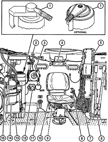
The rigger's area at the cab rear is seen. 1. Personnel heater. 2. Rigger's spotlight remote control. 3. Rigger's troublelight. 4. M17 periscope. 5. Rigger's hatch control. 6. Bolt cutter. 7. Oxygen and acetylene hoses. 8. Rigger's lights. 9. Generator blower air intake grille (hidden). 10. Rigger's seat. 11. Fuel control valve. 12. Rigger's intercom control box. 13. Gas-particulate filter unit. 14. Portable fire extinguisher. 15. Auxiliary power unit air filter housing. (Picture from TM 9-2350-256-10 C1.)
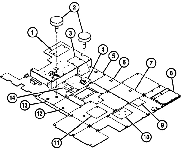
The plates and doors found in the floor of the crew compartment are labeled in this sketch. 1. Main winch fill and level access plate. 2. Two personnel seats. 3. Hydraulic hose connection access plates. 4. Hoist winch fill and level, main winch drain valve access door. 5. Hydraulic hose connection access plate. 6. Hoist winch drain valve access door. 7. Hydraulic oil tank drain access door. 8. Hydraulic connections access door. 9. Hydraulic oil tank fill and oil level indicator access plate. 10. Hydraulic filter gage, mechanical fill level indicator, and drain valve access door. 11. Fuel level sending unit and fuel pump access door. 12. Vehicle jack and utility chain storage access door. 13. Track fixtures, track components, and bilge pump stowage access door. 14. Winch compartment light mount plate. (Picture from TM 9-2350-256-10 C1.)
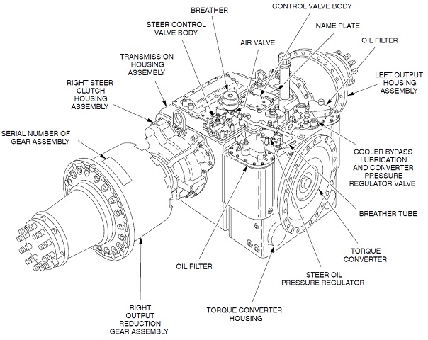
The major external components of the XT-1410-4 transmission are sketched here. Its dry weight was ~6,611lb (~2,999kg), and its length was ~41.17" (~104.6cm), height 31.30" (79.50cm), and width between the output reduction gear assembly mountings was 74.00" (188.0cm). (Picture from TM 9-2520-215-34.)
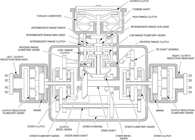
The transmission's major internal components are diagrammed in this image. Its maximum input torque, speed, and horsepower were 1,725 ft-lb, 2,400rpm, and 800, respectively. (Picture from TM 9-2520-215-34.)
The auxiliary power unit was changed to a 10.8hp, 2-cylinder, 4-cycle diesel unit. (Picture from TM 9-2350-256-10 C1.)
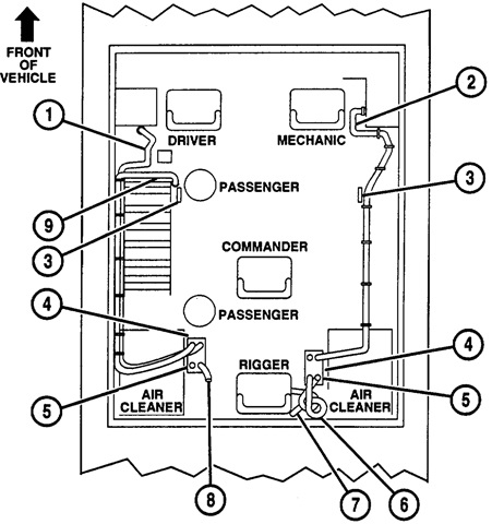
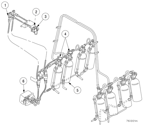
The vehicle was equipped with two gas particulate filter units M8A3, which each supplied filtered air to a maximum of four personnel in the crew compartment. The air was supplied through the crew's individual M25A1 masks. The air purifier assembly M2A2 was composed of a particulate filter M13, a gas filter M12A1, and an air purifier M1A1 all contained in a steel housing. The layout of the system is sketched here. 1. Driver's hose assembly. 2. Mechanic's hose assembly. 3. Circuit breaker and switch assembly. 4. Frame and shock mount assembly. 5. M2A2 air purifier. 6. Commander's hose assembly. 7. Rigger's hose assembly. 8. Passenger's hose assembly. 9. Passenger's hose assembly. (Picture from TM 9-2350-256-10 C1.)
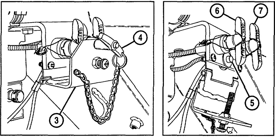
The internal fire extinguisher controls were modified. A shield (3) was added that was secured by a quick-release pin (4). When the shield was lowered, a pushbutton (5) was released, which activated a fuel shutoff solenoid and stopped the engine. Handle (6) discharged the right bank of extinguisher cylinders while handle (7) discharged the left bank. (Picture from TM 9-2350-256-10 C1.)
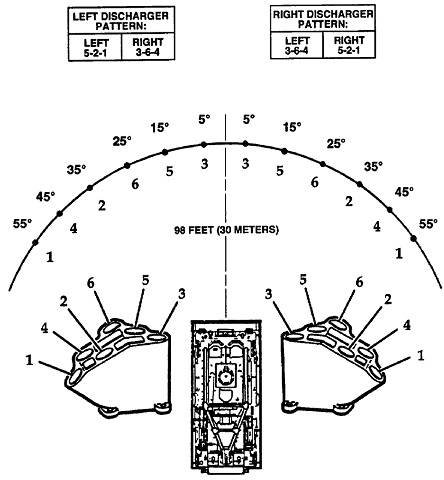
The pattern of smoke emitted from the grenade launchers is sketched here. (Picture from TM 9-2350-256-10 C1.)
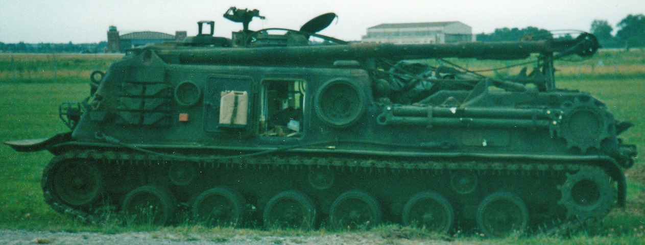
The hatches, including the side personnel doors, commander's cupola, and driver's hatch, are open on this vehicle. The machine gun cradle is present at the commander's cupola, but the gun itself is absent.
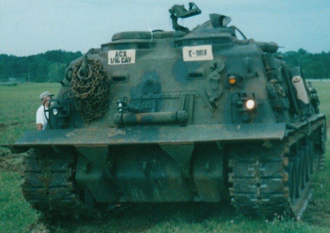
The spade is raised, and the lifting chain is coiled over the normal stowage spot for the 90-ton (81.6-metric ton) snatch block. Only the left-hand headlight is burning.
Similarly, only the left-hand taillight is illuminated. The arrangement of the engine exhaust and the deflector can be seen.
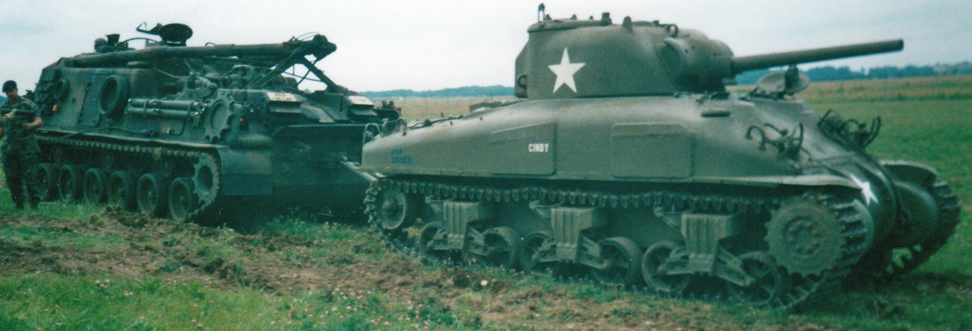
The vehicle in the above pictures was deployed to help "Cindy," cruiser tank Grizzly which had been taking part in a demonstration but had become stranded when its low fuel load and the slope of the terrain conspired to stall its engine.
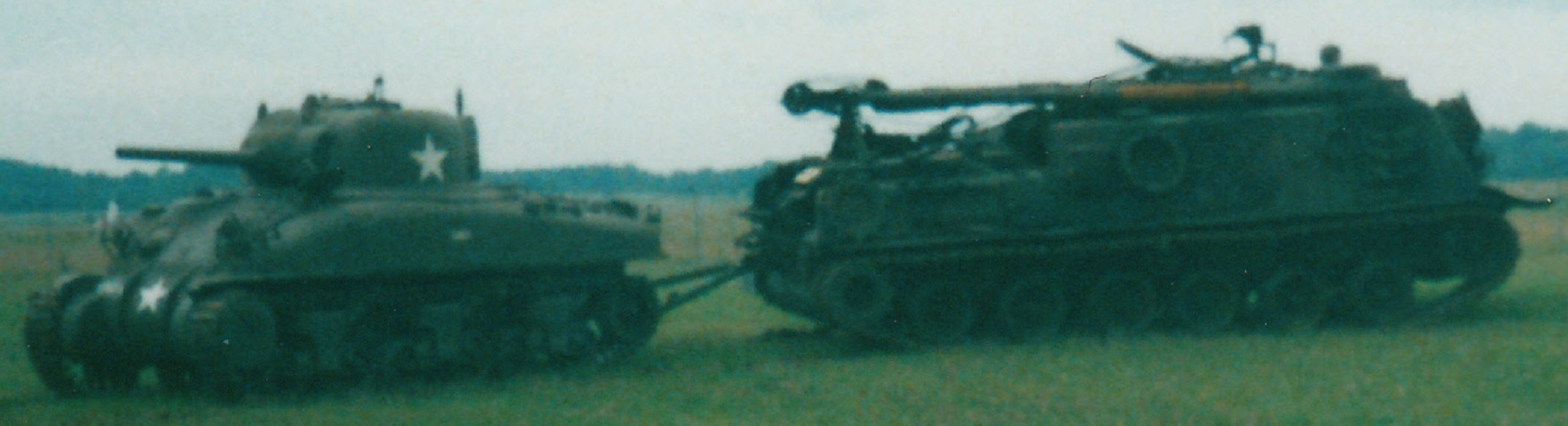
Cindy was able to be restarted once towed to more favorable ground.
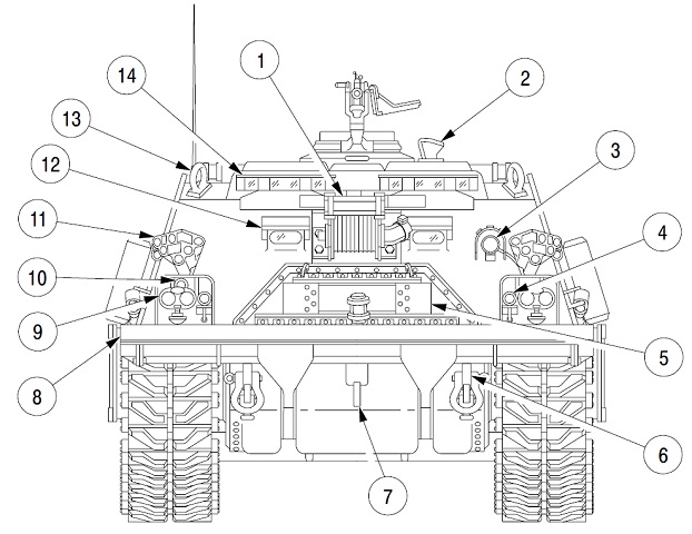
1. Auxiliary winch. 2. Night vision viewer protective cover. 3. Emergency flasher light. 4. Turn signal lamps. 5. Level winder [to spool the main winch cable properly onto the main winch drum]. 6. Towing lugs. 7. Winch lug. 8. Spade. 9. Headlights. 10. Horn assembly. 11. M239 smoke grenade launchers. 12. Vision blocks. 13. Front lifting eyes. 14. M17 periscopes. (Picture from TM 9-2350-292-10.)
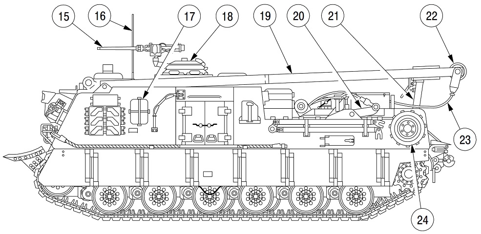
15. M2 .50 caliber machine gun. 16. Antenna. 17. Decontamination kit. 18. Commander's cupola. 19. Boom. 20. Stayline arms [to move the boom rearward during boom operation]. 21. Travel lock. 22. Boom pulleys. 23. Stayline cables [to provide support and control for the boom when it is raised]. 24. Sprocket, roadwheel, and support roller [spares]. (Picture from TM 9-2350-292-10.)
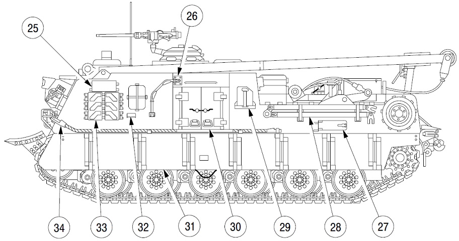
25. Smoke grenade storage box. 26. Auxiliary boom. 27. Left side storage compartment door. 28. Spare tow bar. 29. Oil can. 30. Left side personnel doors. 31. Armor skirt panels. 32. Remote fire extinguisher pull handles. 33. Spare track shoes. 34. Towing cables. (Picture from TM 9-2350-292-10.)
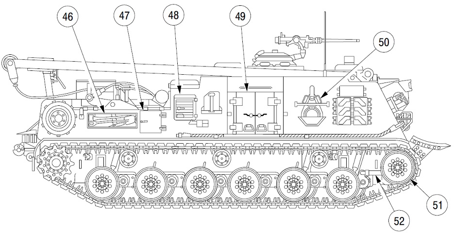
46. Pioneer tools [axe, shovel, and mattock; some vehicles are equipped with an enclosed pioneer tool kit assembly]. 47. Right side storage compartment door [including refuel/defuel controls and impact wrench controls]. 48. Auxiliary power unit (APU) compartment door. 49. Right side personnel doors. 50. 140-ton (127-metric ton) snatch block. 51. Compensating idler wheels. 52. Adjusting link assembly. (Picture from TM 9-2350-292-10.)
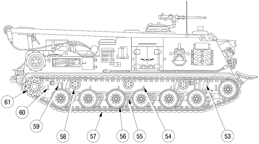
53. Shock absorbers. 54. Stop blocks [steel plates welded to the hull above roadwheels 2 through 5 that limit windup of the torsion bars]. 55. Roadwheel arm. 56. Roadwheel. 57. Track. 58. Support rollers. 59. Bumper stops [two per side]. 60. Tiedown eyes. 61. Drive sprocket. (Picture from TM 9-2350-292-10.)
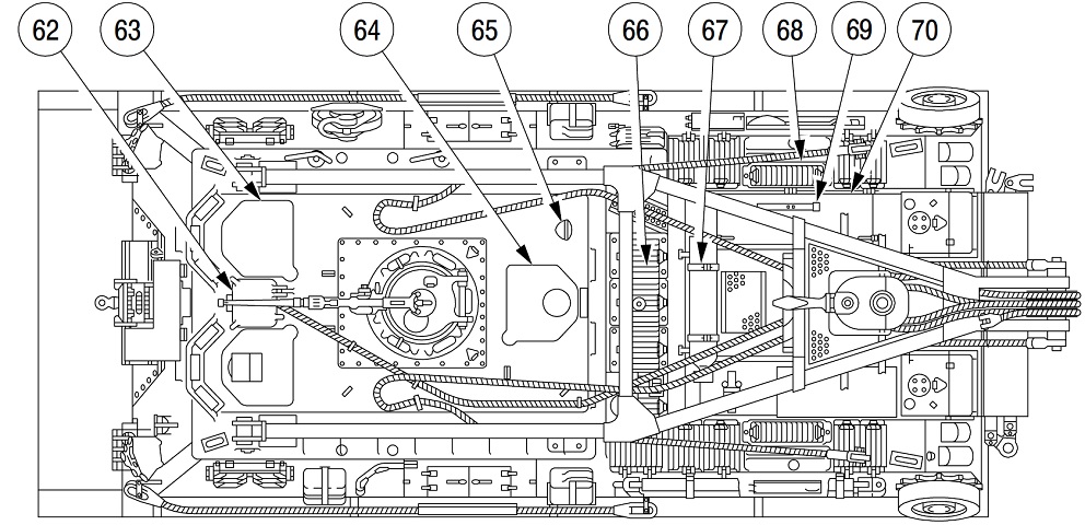
62. Hoist winch cable hatch. 63. Mechanic's hatch. 64. Personnel hatch [not present on all vehicles]. 65. Spotlight. 66. Front engine deck grilles. 67. Oxygen cylinder. 68. Engine deck side grille. 69. Sledge hammer. 70. Engine deck door [may be a split door on some vehicles]. (Picture from TM 9-2350-292-10.)
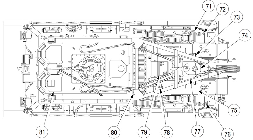
71. Engine deck grille doors. 72. Rear lifting eyes. 73. Retaining straps [to secure the hook block in the boom tray]. 74. 35-ton [32-metric ton] hook block. 75. Engine deck storage box. 76. Auxiliary power (NATO slave) receptacle. 77. Boom tray. 78. Vise. 79. Engine deck storage tray. 80. Fuel filler cap protective cover. 81. Driver's hatch. (Picture from TM 9-2350-292-10.)
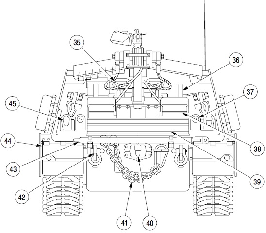
35. Vision blocks. 36. Auxiliary boom receptacles [eight]. 37. Rear service lights. 38. Exhaust grille. 39. Exhaust deflector. 40. Towing pintle. 41. Combat tow chain. 42. Towing lugs. 43. Tow bar. 44. Rear fender skirt. 45.Taillight assembly. (Picture from TM 9-2350-292-10.)
The driver's brake pedal (20) and dimmer switch (19) were revised with the introduction of brake modulation. (Picture from TM 9-2350-292-10.)
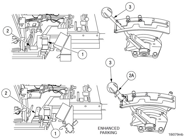
An enhanced parking feature was instituted with the revised brake pedal configuration. It was necessary to pull up on the T-handle to shift the selector into park. 1. Accelerator pedal. 2. Brake pedal. 2A. T-handle. 3. Shift transmission selector. (Picture from TM 9-2350-292-10.)
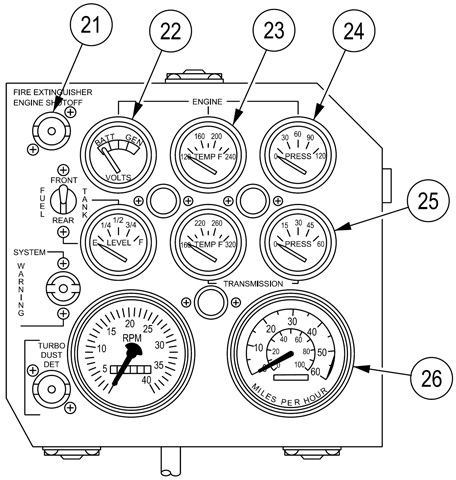
The driver also received a new gauge panel. 21. Fire extinguisher engine shutoff indicator. 22. Battery-generator indicator gauge. 23. Engine oil temperature gauge. 24. Engine oil pressure gauge. 25. Transmission oil pressure gauge. 26. Speedometer/odometer.
Under the fire extinguisher engine shutoff indicator was the fuel tank toggle switch; the fuel level gauge was just to its right. The transmission oil temperature gauge was between the fuel level and transmission oil pressure gauges. The system warning indicator was under the fuel tank toggle switch, and the tachometer/hour meter was the large gauge to its lower right. The turbo dust detection indicator was to the tachometer's lower left. (Picture from TM 9-2350-292-10.)
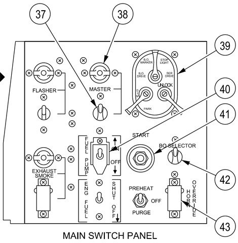
The main switch panel was also reconfigured. 37. Master toggle switch. 38. Master toggle switch indicator. 39. Vehicle light switch. 40. Fuel pump toggle switch. 41. Start pushbutton. 42. Blackout selector toggle switch. 43. Warning horn override toggle switch.
At the upper left was the flasher indicator, with the flasher toggle switch directly below. At the bottom left was the exhaust smoke toggle switch, with its indicator directly above. The engine fuel shut off toggle switch was to the right of the exhaust smoke toggle switch, and to its right was the preheat/purge toggle switch. The preheat position activated the manifold heater system to aid in cold-weather starting, and the purge position activated the purge pump to purge air from the main fuel system prior to starting the vehicle. (Picture from TM 9-2350-292-10.)
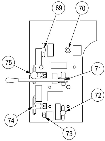
The hydraulic controls can be contrasted with the earlier machines above. 69. BOOM operating lever. 70. SYSTEM SELECTOR control valve handle. 71. SPADE bidirectional control valve handle. 72. AUX WINCH bidirectional control valve handle. 73. BOOM SAFETY directional control valve handle. 74. HOIST WINCH bidirectional control valve handle. 75. MAIN WINCH bidirectional control valve handle. (Picture from TM 9-2350-292-10.)
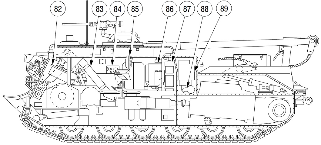
82. Hydraulic control valve manifold. 83. Hoist winch cable chute. 84. Communications system. 85. Commander's seat. 86. Air cleaner. 87. Personnel heater. 88. Auxiliary hydraulic pump. 89. Auxiliary power unit (APU). (Picture from TM 9-2350-292-10.)
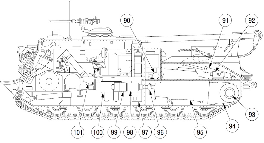
90. Motor/generator. 91. Stayline cylinders. 92. Refuel/defuel pump. 93. Output reduction drives. 94. Transmission. 95. Main engine. 96. Power takeoff (PTO). 97. Hydraulic reservoir. 98. Electromagnetic clutch [to engage/disengage main engine from hydraulic pumps]. 99. Hydraulic pumps. 100. Filter manifold. 101. Subfloor stowage baskets. (Picture from TM 9-2350-292-10.)
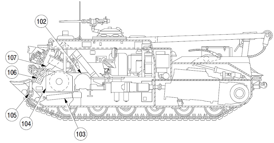
102. Hoist winch. 103. Spade cylinders. 104. Main winch. 105. Spade lock. 106. Level winder cylinder. 107. Boom cylinders. (Picture from TM 9-2350-292-10.)
One of two types of auxiliary power units could be found, either the ONAN 10.8hp, 2-cylinder, 4-cycle, air-cooled diesel unit shown on the left or the HATZ 17.5hp, 2-cylinder, 4-cycle, air-cooled diesel unit on the right. 1. Voltage regulator. 2. Engine. 3. Starter/generator. 4. Auxiliary hydraulic pump. 5. Circuit breaker reset button. (Picture from TM 9-2350-292-10.)
A schematic of the fixed fire control system is drawn in this sketch. 1. Dual pull mechanism. 2. Engine shutoff switch. 3. Interior remote control handles. 4. Cylinder control valve. 5. CO2 cylinder. 6. Exterior remote control handles. (Picture from TM 9-2350-292-10.)
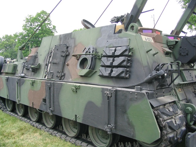
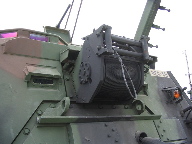
The ballistic skirts and other additional armor (visible if the side armor and armor around the front vision blocks are compared with the earlier vehicle above) increased the M88A2's weight to the point that it could better deal with the Abrams tanks. The .50cal MG is mounted on the commander's cupola, and the lifting boom is raised. Spare track blocks are stowed on the side of the cab, and a snatch block is stowed behind these.
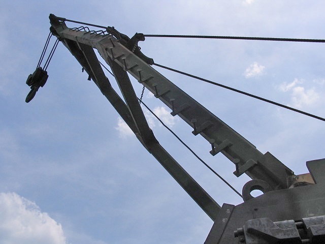
Details of the rigging of the lifting boom can be gleaned from this image.
The auxiliary winch that helped with outlay of the main winch cable was mounted on the front of the vehicle. The driver and mechanic were provided with vision blocks around their hatches and one each in the front slope of the cab. The opening for the main winch cable can be seen at the bottom of the picture.
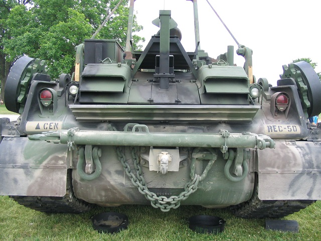
The rear of the vehicle is shown here. The tow bar and combat tow chain are stowed on the rear, and extra road wheels and drive sprockets are mounted to the sides of the vehicle. The twin exhaust doors flank the boom support.
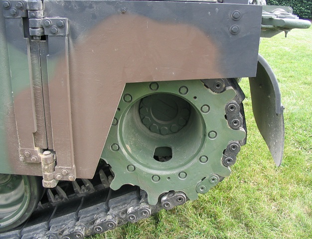
Details of the drive sprocket and mounting of the ballistic skirts are shown here.
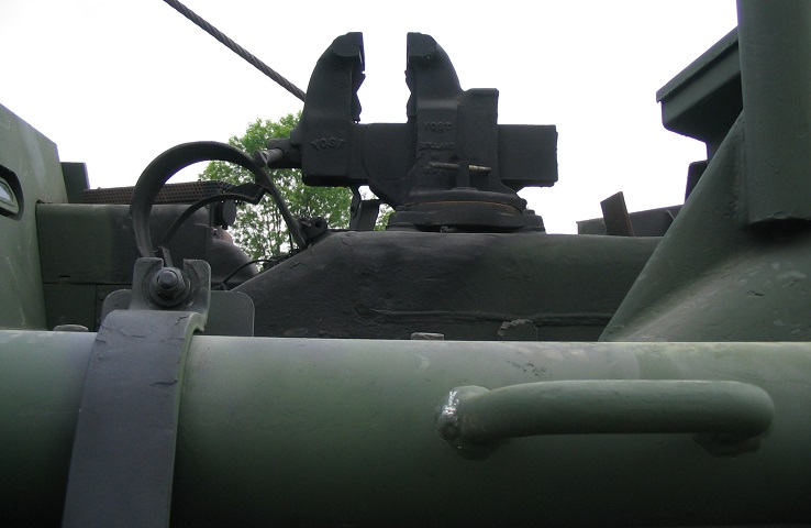
A close-up of the vise mounted on the left rear of the vehicle is provided here. Note the vision block in the rear of the cab, just visible to the left of the image.
The commander's seat is lowered beneath his cupola here. The red toggle switch below the commander's cupola was for arming the vehicle's smoke grenade launchers.
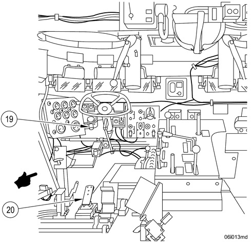
Looking forward to the driver's and mechanic's positions, we can see the transmission shift lever and the hydraulics control panel detailed above.
