Medium Tank M1.
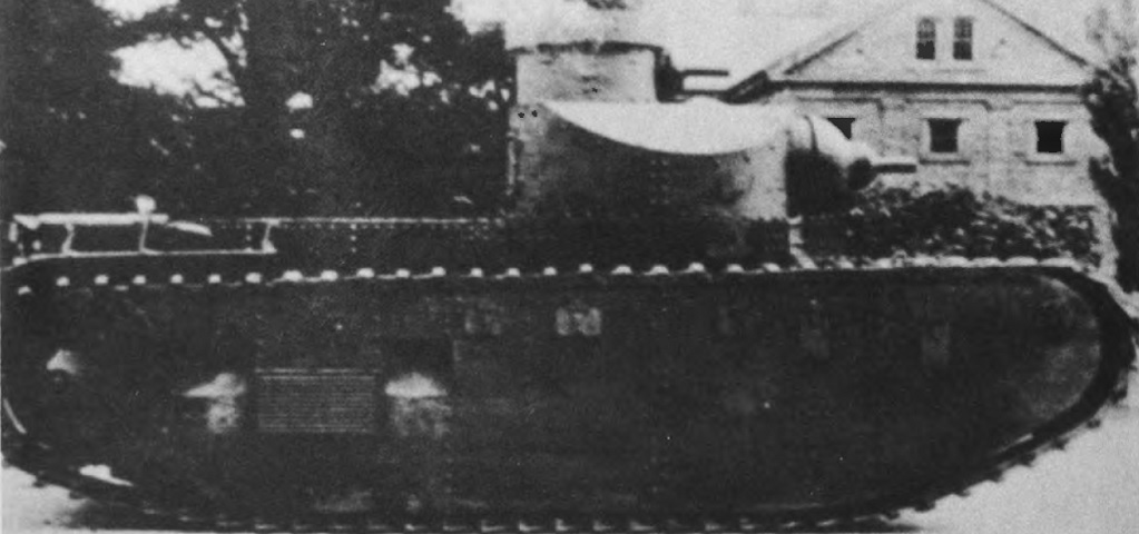
The suspension, designed by Holt engineer Emil Francis Norelius, and running gear of the M1 were almost totally protected by plates. The large machine gun-armed commander's cupola would look at home on the M48 and M60 tanks that would appear decades later. (Picture from Development of Armored Vehicles, volume 1: Tanks.)
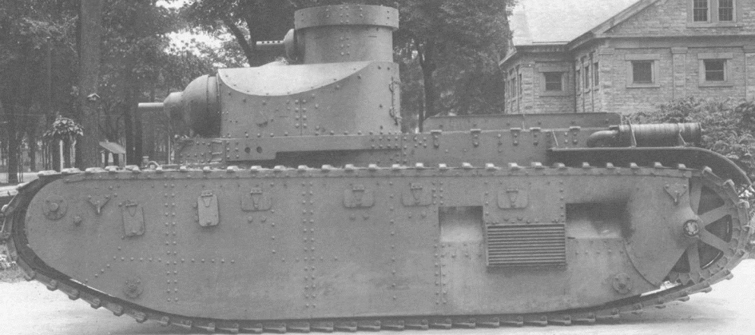
A clearer image of the tank's opposite side is provided here from the same series as the above. (Picture from Tank Data, vol. 2.)
The beveled shape of the turret and the open design of the tracks can be seen in this picture. The driver was provided with two outward-opening doors in the front of the hull as well as a flap with an integral vision slit. Note that there are two sighting apertures for the cupola machine gun: one was for a telescopic sight, and the other was a direct vision port closable with a plug. The machine gun itself was offset to the right in the mount. (Picture from Tank Data, vol. 2.)
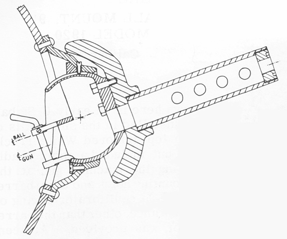
A cross-section of the 7½" (19cm) cupola ball mount is sketched here. The ball was a hollow one-piece unit with an integral cradle for the machine gun, whose forward bearing surface was a structurally mounted conical flange. An antirotation pin inserted through the installation flange into a groove on the ball's surface kept the gun from rotating about its axis due to its off-center placement. The gun barrel protection tube was screwed into the shield. (Picture from Weapon Mounts for Secondary Armament.)
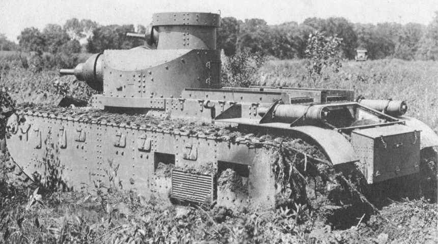
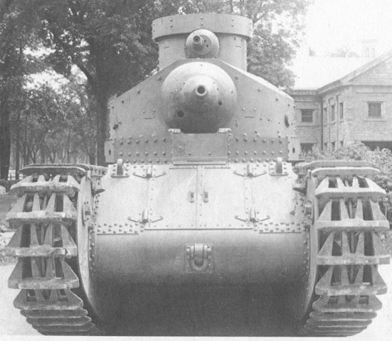
Details of the engine compartment and the vehicle's rear are seen here. An exhaust pipe was placed on each side fender, and the mud clearing chutes in the side skirts are being put to good used in the apparently marshy terrain. The turret overhang of the tracks is more easily seen from this angle. (Picture from Tank Data, vol. 2.)
