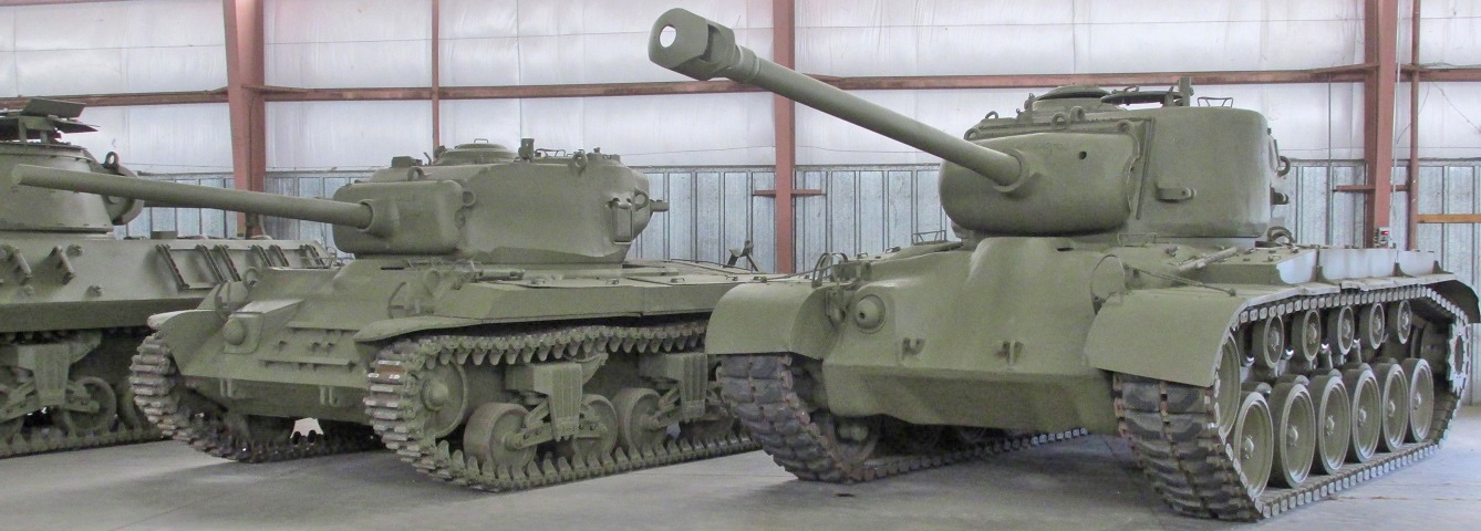
Medium Tank T23 belonging to the US Army Armor and Cavalry Collection.
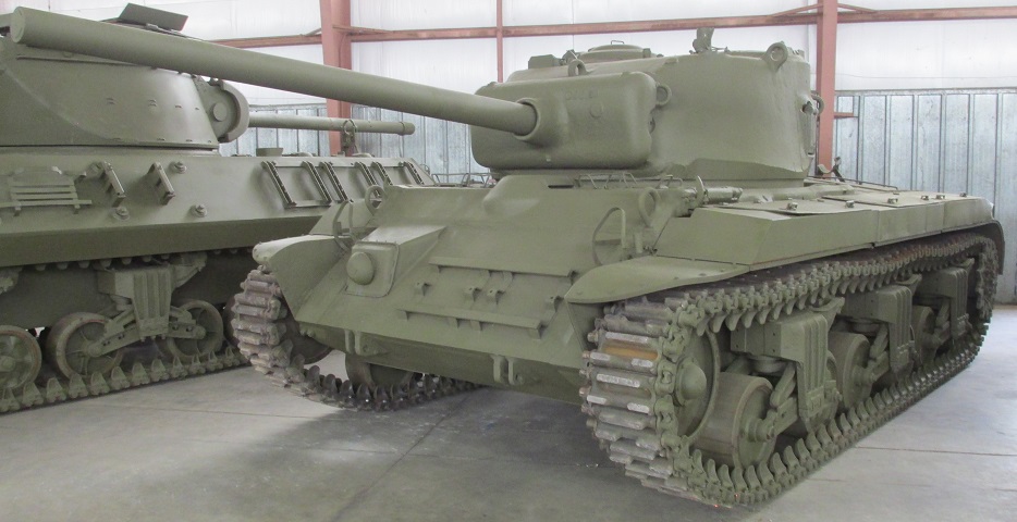
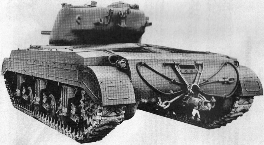
Compared with the medium tank M4, the T23 featured a much lower box-type hull that lacked sponsons over the tracks. Stowage boxes line both fenders. The T23 was not accepted for service due to reasons of excessive maintenance requirements and the potential need to retrain maintenance personnel for its electric drive system, however its turret formed the basis of the 76mm gun turret seen on the M4 Sherman.
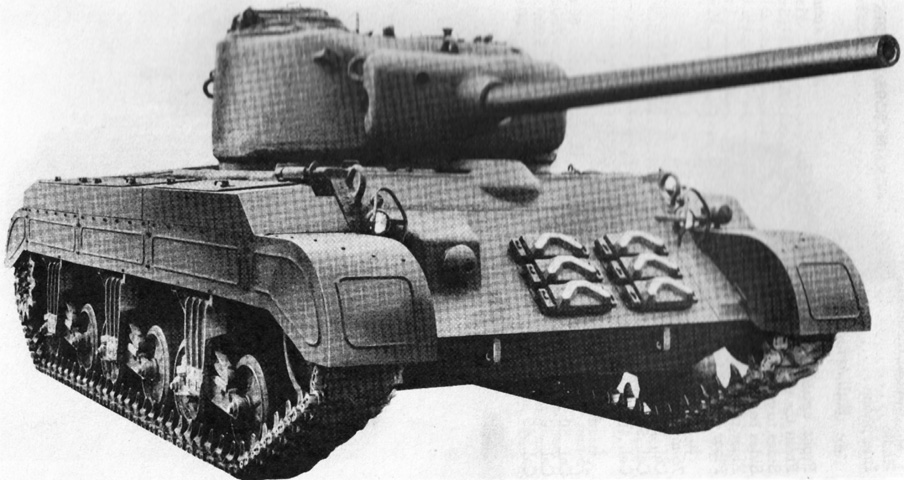
Spare tracks and sand shields are present on this tank. (Picture from TM 9-734 Medium Tank T23.)
The engine exhaust was routed through a port in the rear between the legs of the gun travel lock. A towing pintle could be installed centrally at the bottom between the two towing lugs, and the claw-like fittings all over the hull rear were for the stowage of a towing cable.
A closer look at the rear is provided in this image. Note that the hull rear is made up of two sections that came together under the center of the exhaust port.
The intricate stowage of the tow cable is illustrated on this tank. The gun travel lock is folded down, and the towing pintle is mounted. Note that the turret lacked the rear ventilator that was eventually added in turrets for 76mm gun M4 Shermans, since the rotoclone blower installed between the drivers was sufficient for ventilation. (Picture from TM 9-734 Medium Tank T23.)
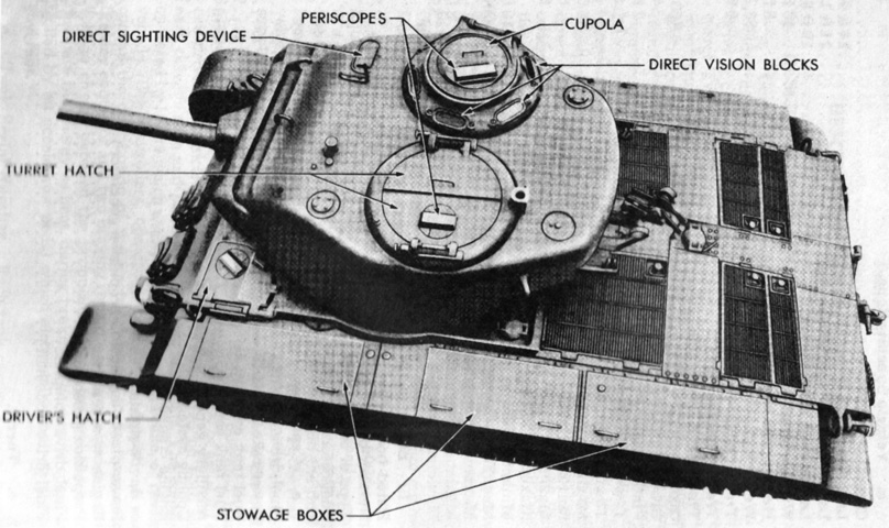
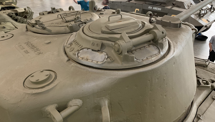
The commander was provided with a vision cupola, and the loader with a split hatch similar to the hatches on earlier medium tanks M4 with a rotating socket for a .50cal machine gun. (Picture from TM 9-734 Medium Tank T23.)
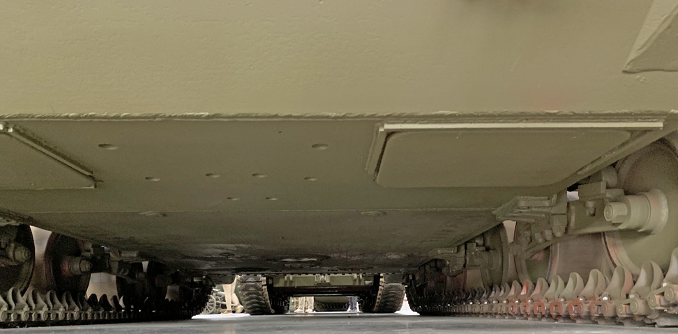
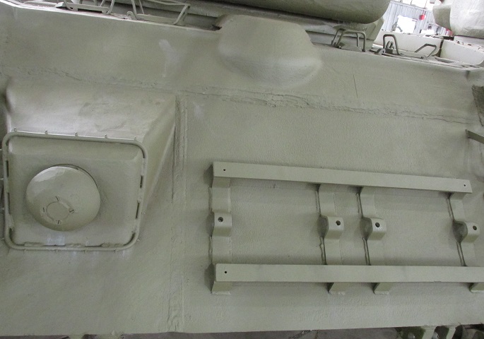
The locations of the driver's floor escape hatches are illustrated from this view of the hull floor plates.

Access panels for the engine and generator compartments were found on the bottom of the rear hull. The left towing lug and the towing pintle socket can be seen along the top of the image.
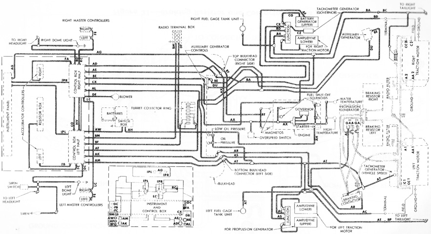
This schematic illustrates the complex routing of conduit necessitated by the electric drive system. (Picture from TM 9-734 Medium Tank T23.)
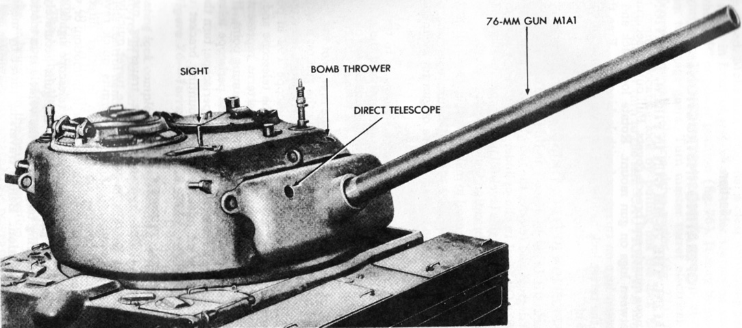
The familiar shape of the turret and combination gun mount M62 would see widespread use in the medium tank M4. The 2" smoke mortar M3 was installed in front of the loader's position. (Picture from TM 9-734 Medium Tank T23.)
The lower rim of the turret features significant machining to allow it to clear various hull fixtures. The assistant driver's periscopes can be seen as well.
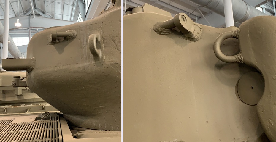
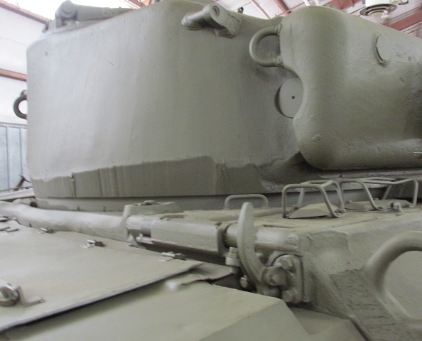
Mounts for a hoist to assist in tasks such as removing the engine were welded to the turret; they are seen here on the left at the turret's right rear between the lifting eye and the machine gun stowage, and on the right at the turret's right front. The gunner's periscope visible in the right image has also been plated over.
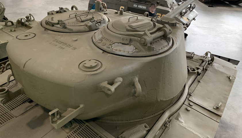
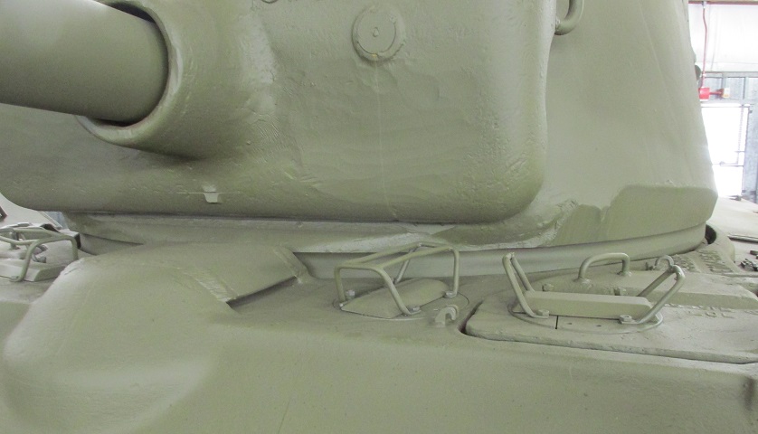
The commander's vision blocks have been plated over, but his cupola and the loader's split hatch combine to span the turret roof. The loader's rotating hatch ring incorporated a socket for a .50cal machine gun, and the rear of the turret features a socket and brackets for stowing the .50cal when not in use. Antenna mounts are present at the rear corners of the turret roof, and a mount for a spotlight can be seen on the forward roof of the turret ahead of the loader's hatch. A fuel filler is present in the hull roof at each rear corner of the turret.
A closer look at the commander's cupola is provided here. The gunner's periscope head emerged from the turret roof ahead of the cupola, and to the left of this is the commander's vane sight that was used to roughly bring the turret onto a target. A third antenna mount can be seen on the far corner of the turret roof on the other side of the loader's hatch.
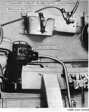
The commander was provided with an override traverse handle on the right turret wall. By pressing the button on top of the handle and moving it forward to traverse left or backward to traverse right, inputs from the gunner's hydraulic control handle would be cut. (Picture from TM 9-734 Medium Tank T23.)
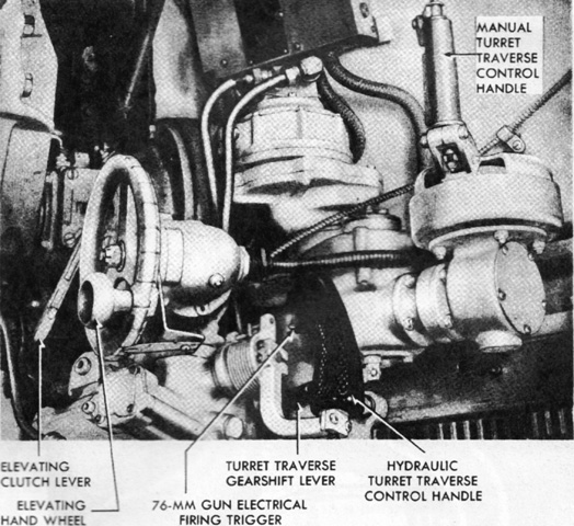
The gunner's controls are labeled in this image. Hydraulic traverse was accomplished by rotating the hydraulic turret traverse control handle to the right or left once the system was energized. Elevation was manual only and accomplished by the elevating hand wheel. (Picture from TM 9-734 Medium Tank T23.)
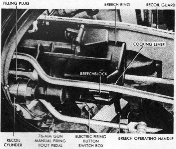
The 76mm gun was mounted so that the breech closed towards the loader. The gunner could fire the 76mm gun electrically by the right-side foot button on the electric firing button switch box or by a trigger on his hydraulic traverse handle. To manually fire the gun, the manual firing foot pedal was used. (Picture from TM 9-734 Medium Tank T23.)
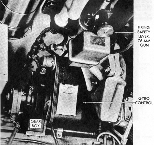
The stabilizer gear box and gyro control were mounted on the underside of the 76mm gun. The firing safety lever was moved to the FIRE position by pulling it down and rotating it a quarter-turn in either direction. (Picture from TM 9-734 Medium Tank T23.)
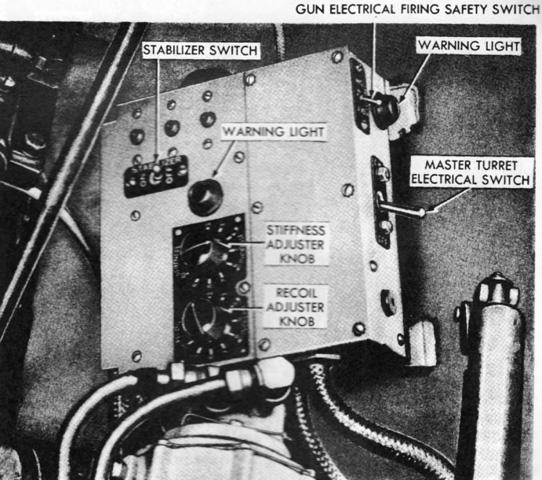
The turret control box allowed the gunner to turn on or off turret electrical power, the gun stabilizer, and the gun firing circuit. The stabilizer's recoil and stiffness could be adjusted at the box as well. The stabilizer's stiffness was too high if the gun vibrated, and too low if the gun failed to remain in its aimed or set position. The recoil adjustment prevented the breech end of the gun from dropping during recoil. (Picture from TM 9-734 Medium Tank T23.)
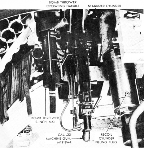
The loader's side of the turret front is seen here. The coaxial machine gun was fired electrically by the left-side button on the gunner's floor switch box. It could also be fired manually by lifting its trigger by hand. The 2" bomb thrower was loaded by snapping the operating handle a quarter-turn to the left, then hinging the breech downward. The smoke projectile was dropped into the breech, then the breech was secured by closing and snapping the handle back to the right. The bomb thrower was fixed in elevation, and aimed in azimuth by traversing the turret. (Picture from TM 9-734 Medium Tank T23.)
The drivers were each provided with a periscope in their hatch as well as one in the hull roof. The aperture for the rotoclone ventilator can be seen on the roof between the drivers.
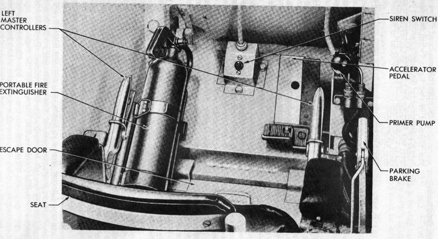
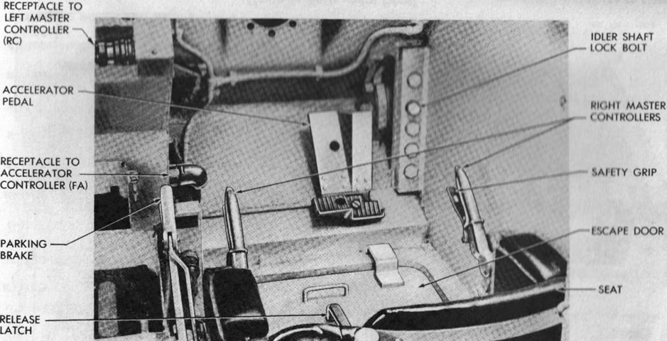
The driver's position is labeled in this image. The master controller steering levers featured smaller safety grips that needed to be held closed against the steering levers while the tank was being controlled. These levers were released if the vehicle was to remain at rest. (Picture from TM 9-734 Medium Tank T23.)
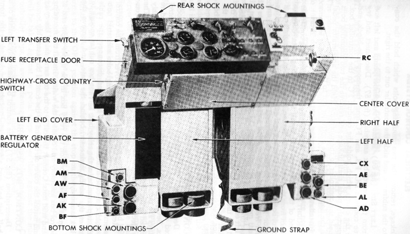
The control box consisted of right and left halves attached to a shock-mounted frame installed between the drivers. The instrument panel, resistor box, and accelerator controllers were mounted on the control box assembly, and the right and left halves contained voltage regulating equipment for the battery charging system and some of the power transmission controls. Transfer switches were found on the right and left sides of the control box. These switches were mounted on a common shaft, and were used to transfer control between the driver and the assistant driver, since only one position at a time could control the tank. The two-letter codes refer to different electrical conduits. (Picture from TM 9-734 Medium Tank T23.)
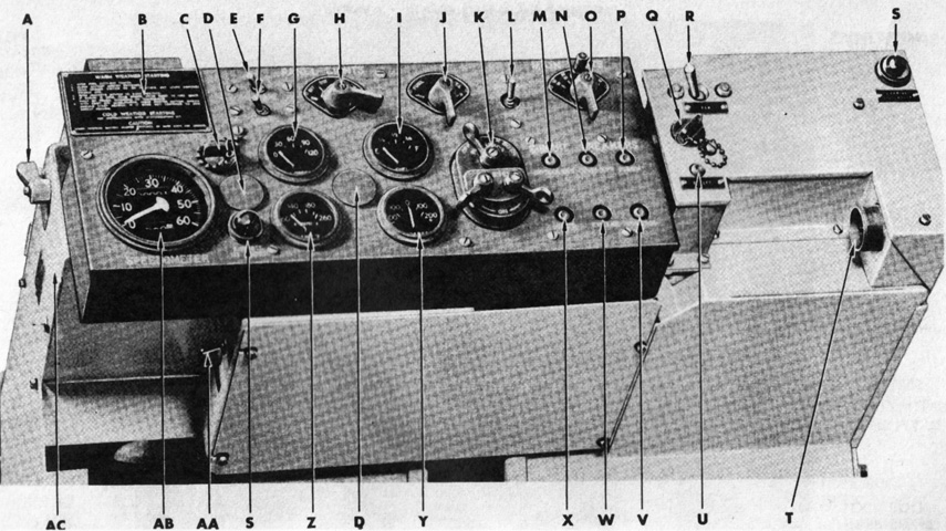
The driver's instrument panel is labeled here. The driving controls did not function if the control switch was turned off. The HIGHWAY position of the highway-cross country switch was used during general operation and provided more precise control. The CROSS-COUNTRY position enabled greater pulling power for tougher terrain.
A. Control transfer switch (left). B. Starting instruction plate. C. Utility outlet receptacle. D. Instrument light cover. E. Control switch. F. Engine switch. G. Engine oil pressure gage. H. Panel light switch. I. Fuel level gage. J. Fuel tank selector switch. K. Magneto and starter switch assembly. L. Engine stop switch. M. Headlight circuit breaker. N. Dome light circuit breaker. O. Main light switch. P. Siren circuit breaker. Q. Utility outlet receptacle. R. Crew compartment blower switch (fan). S. High water and low oil pressure warning light. T. Connector (LC) to left master controllers. U. Outlet circuit breaker. V. Control circuit breaker. W. Engine circuit breaker. X. Instruments circuit breaker. Y. Ammeter. Z. Water temperature gage. AA. Highway-cross country switch. AB. Speedometer. AC. Battery charging generator fuse and instrument panel outlet circuit breaker box. (Picture from TM 9-734 Medium Tank T23.)
The projection for the bow machine gun is shown here, and the weld lines for the various plates and castings that make up the glacis are also visible.
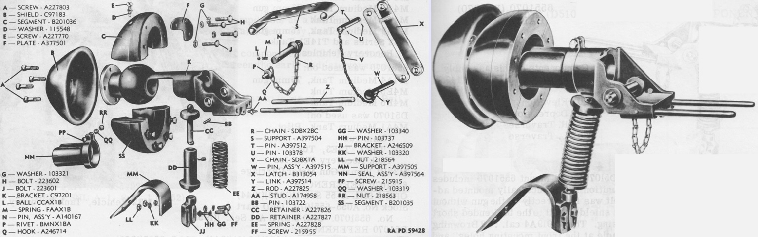
Exploded and assembled views of the D93884 caliber .30 ball mount are seen on the left and right, respectively. The D93884 was similar to the 6551070 found on the medium tank M4. A travel lock was provided that was hinged from above. (Picture from Weapon Mounts for Secondary Armament.)
The assistant driver was provided with a duplicate set of driving controls. (Picture from TM 9-734 Medium Tank T23.)
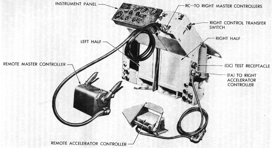
The remote controllers are seen in this image connected to the control box. The remote master controller could be mounted at the commander's position or used when walking alongside the tank. The remote accelerator controller could be installed, for example, on the commander's lower seat or at the left driving position. If the tank needed to be moved in close quarters or where power output didn't exceed 1,300 engine rpm, the remote accelerator controller was optional. (Picture from TM 9-734 Medium Tank T23.)
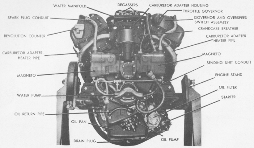
The GAN engine is seen here from the rear. Similar to the GAA of the medium tank M4A3 and GAF of the medium tank M26, it displaced 1,100in³ (18,000cm³) with a 5.4" (14cm) bore, 6" (15cm) stroke, and 7.5:1 compression ratio. The engine was 59.02" (149.9cm) long, 33.25" (84.46cm) wide, and 47.78" (121.4cm) high, and weighed 1,300lb (590kg). It differed from the GAA by using two Stromberg Model HD-5 or HH-5 carburetors instead of the former's Model NA-Y5G carburetors; having an hydraulic electric instead of a mechanical governor; and mounting a special flywheel that acted as the driving plate for the propulsion generator. (Picture from TM 9-1731B Ordnance Maintenance--Ford Tank Engines (Models GAA, GAF, and GAN).)
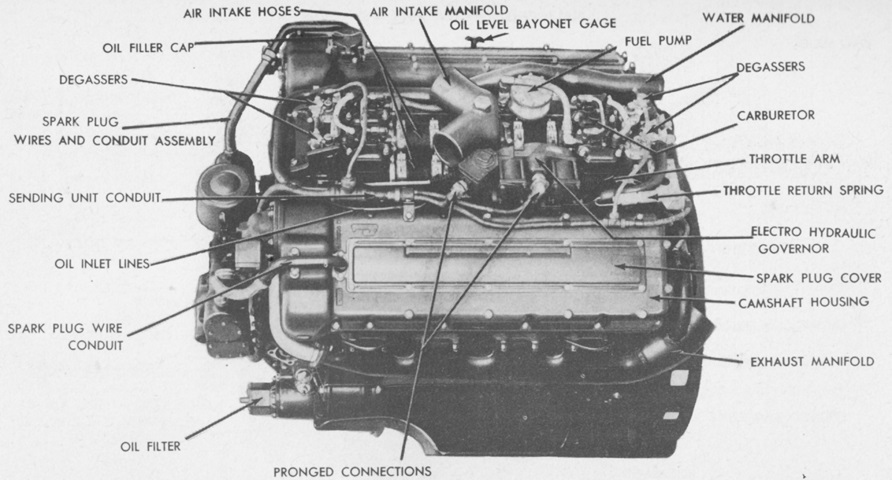
A carburetor and the electric hydraulic governor are visible in this side view. (Picture from TM 9-1731B Ordnance Maintenance--Ford Tank Engines (Models GAA, GAF, and GAN).)
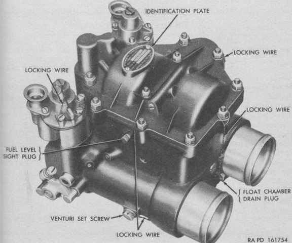
Designed for tracked vehicles, the Stromberg Model HH-5 was a dual horizontal carburetor with neither a choke nor power system. There was a single accelerating pump system that was actuated by a throttle valve plate shaft, and each barrel had its own metering and idle system. It was completely sealed: air used for venting the float chamber and for air bleeds was sourced from the air intake sleeves. A degasser assembly was present for each barrel; these would automatically shut off fuel to the idle system when the manifold vacuum was high. When the engine was turned off, an electric control provided positive shut-off of fuel. (Picture from TM 9-8625/TO 19-75CCA-7 Carburetors (Stromberg).)
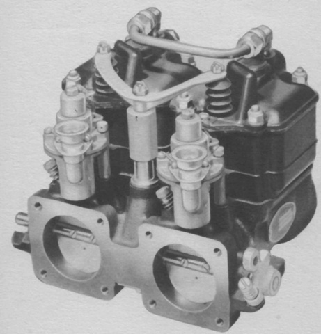
Also designed for tank engines, the Stromberg HD-5 carburetor was a double-barrel horizontal type with each barrel having its own fuel system, main metering system, idle system, accelerating system, and degasser. and two floats connected by one lever and operating on one needle valve. Each barrel had its own main metering and idling system and degasser. A single throttle operated both barrels. (Picture from TM 9-1826B Ordnance Maintenance--Carburetors (Stromberg).)
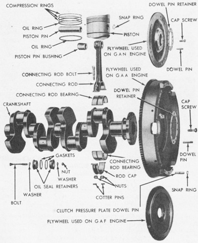
The special flywheel of the GAN engine is visible at the top, and can be compared with the conventional flywheel found on the GAA engine in the center. (Picture from TM 9-1731B Ordnance Maintenance--Ford Tank Engines (Models GAA, GAF, and GAN).)
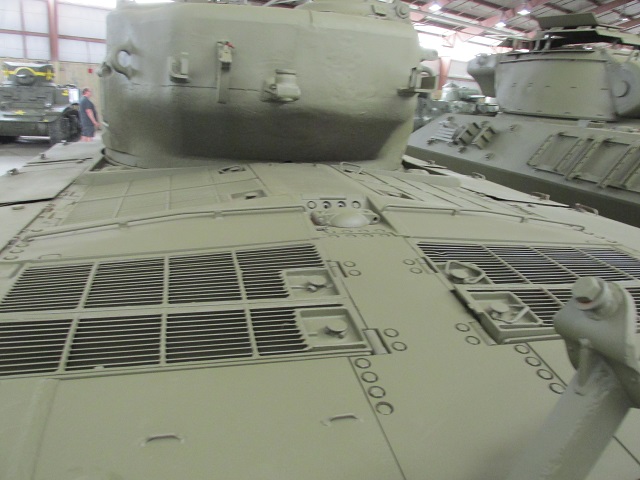
The engine deck is shown here. The louvres closest to the camera were for air outlet, while those toward the turret were for air inlet. The left and right braking resistors and track driving motors were under the air outlet louvres, while the generator and GAN engine were further forward under the air inlet louvres. Stowage for the antiaircraft machine gun is provided on the turret bustle.
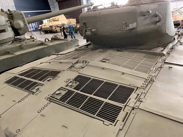
Further details of the engine deck are seen here, including the coolant filler cover in the center.
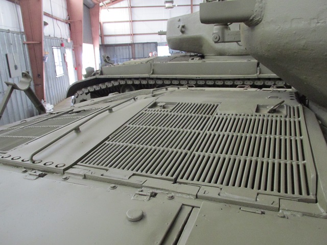
The air inlet louvres are shown here. The louvres were all hinged at the outside.
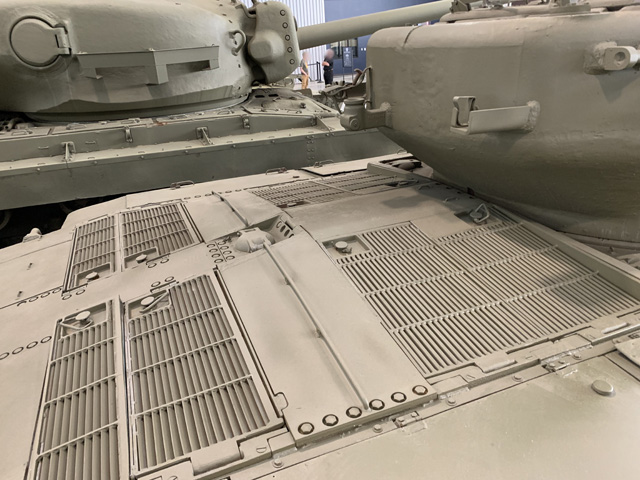
A steeper angle makes the coolant filler cover in the center of the rear deck easier to see.
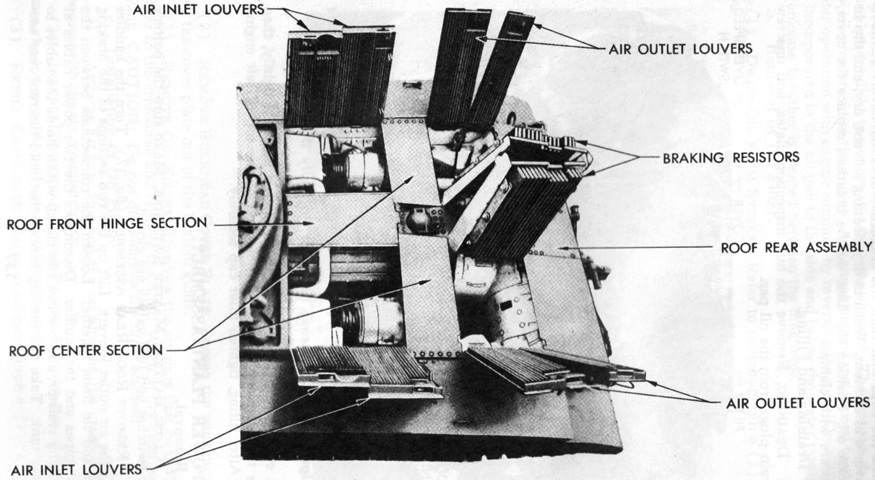
The louvres are seen open, revealing a look into the engine compartment. Braking contactors were shock-mounted in the air duct between the left radiator and left traction motor; these automatically opened or closed to break or provide a direct electrical connection between the propulsion generator and the traction motors for braking or motoring, respectively. The two braking resistors labeled in this image were mounted in hinged frames under the air outlet louvres, and were connected into the electrical circuit by copper braid connectors. The braking resistors took the energy generated by braking the tank and dissipated it as heat. (Picture from TM 9-734 Medium Tank T23.)
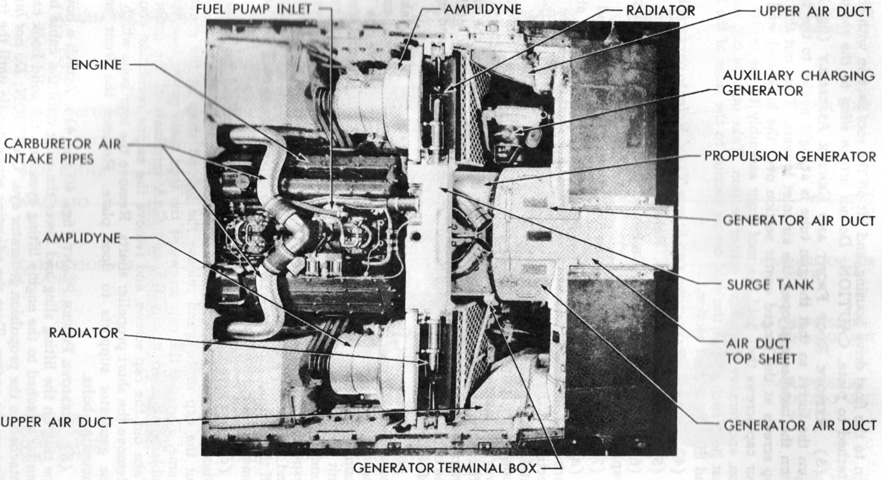
The top armor and louvres have been removed, and the powerplant can be seen. The engine was coupled directly to a direct-current propulsion generator that furnished the electrical energy to each track's traction motor mounted in the final drive housing. (Picture from TM 9-734 Medium Tank T23.)
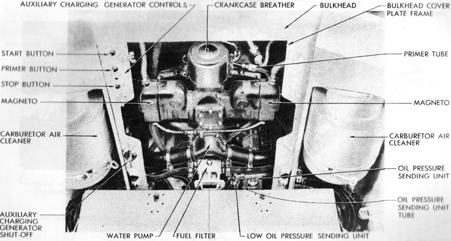
The engine is seen here after the cover plate was removed from the rear bulkhead in the crew compartment. The flywheel end of the engine was considered its front, while the right or left side were determined by looking at the engine from the magneto end. (Picture from TM 9-734 Medium Tank T23.)
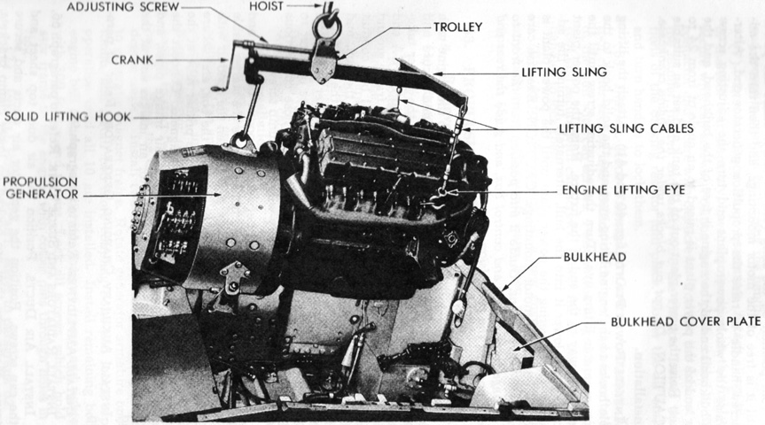
The GAN and propulsion generator are being removed. (Picture from TM 9-734 Medium Tank T23.)
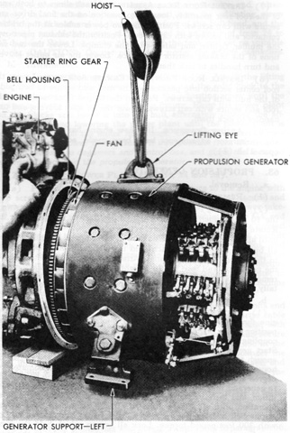
The 6-pole, direct current, commutating-pole General Electric 5 GT-563-A1 propulsion generator and its coupling are shown here being disconnected from the engine. The propulsion generator included a fan, coupling, and ring gear, and weighed 2,036lb (923.5kg). (Picture from TM 9-734 Medium Tank T23.)
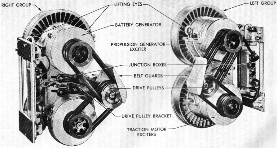
Three amplidyne exciters were used to control the field excitation of the propulsion generator and the two traction motors. Two amplidynes were mounted to the left hull wall in the engine compartment, and the third was mounted to the right hull wall in combination with the battery charging generator. The amplidynes were identical except for their drive mechanisms: the lower amplidynes used a three-groove pulley driven by two belts, while upper amplidyne and the battery charging generator used a five-groove pulley and three belts. The belts were driven from a main drive pulley mounted with an adjustable bracket to the amplidyne assembly mounting bracket, which was itself driven by right angle drive gear boxes mounted on the rear of the engine compartment bulkhead. The right angle drives were driven by short jack shafts from the engine's power take-off. (Picture from TM 9-734 Medium Tank T23.)
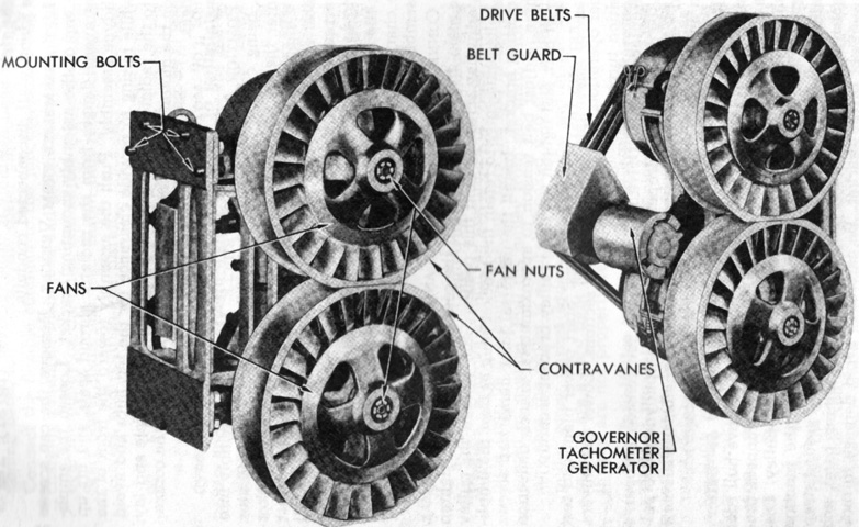
The amplidynes and battery charging generator were all equipped with a ventilating fan and a contravane. The contravanes directed air through the radiators and assisted the propulsion generator's fan in circulating air through the air ducts and cooling the traction motors and propulsion generator. (Picture from TM 9-734 Medium Tank T23.)
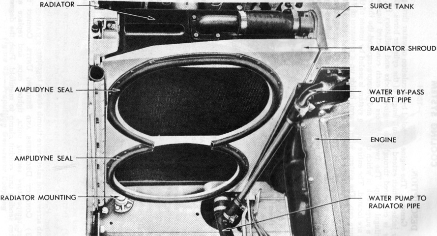
The engine's cooling system held 16gal (61L) of water, and used two radiators each connected with a surge tank. The radiators were held in place by shock mountings, and seals between the radiators and amplidynes in the radiator shrouds helped to direct air from the amplidynes to the radiators for cooling. (Picture from TM 9-734 Medium Tank T23.)
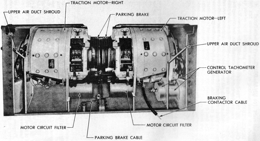
The final drive assembly contained two direct-current traction motors, with their gear reduction units, that drove the rear drive sprockets. The motors were independent of each other, and could drive or brake their tracks individually over the entire range of speed or tractive effort. The parking brakes were connected to the spline shaft extension on the commutator end of the traction motors, and could also be used to stop the tank in an emergency. The control tachometer generator was a totally enclosed, direct-current machine that controlled horsepower output, heating, and maximum speed of the traction motors. It was driven by a pinion that meshed with the left traction motor gear train and was connected to the electrical circuit by a coupling ring on its flange mount. The motor circuit filters consisted of a coil and capacitor enclosed in a cylindrical metal container, and suppressed the static caused by the traction motors that contributed to radio reception interference. (Picture from TM 9-734 Medium Tank T23.)
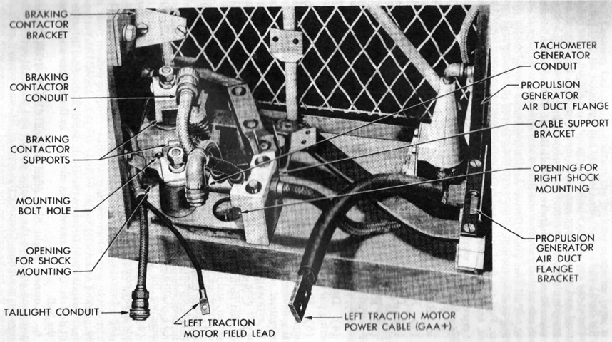
The left rear of the hull is shown here with the final drive removed. (Picture from TM 9-734 Medium Tank T23.)
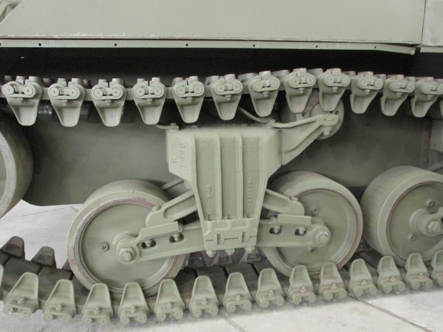
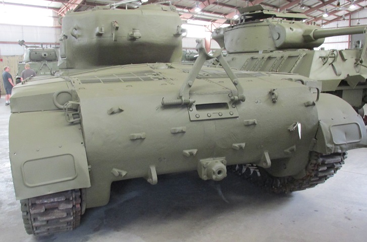
The T23 used the same vertical volute spring suspension as found on the M4 Sherman. This tank's suspension features the raised return roller arms that were intended to decrease wear on the track skids that was caused by steel track.
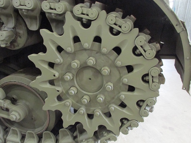
The drive sprockets were at the rear of the tank, obviating the need for a propeller shaft running through the fighting compartment.
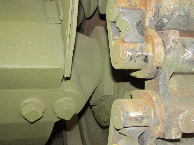
Conversely, the adjustable idler was moved to the front. A large wrench was used to engage the hexagonal fitting and move the wheel in or out as needed.
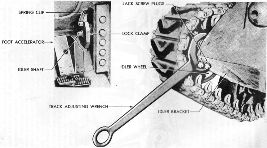
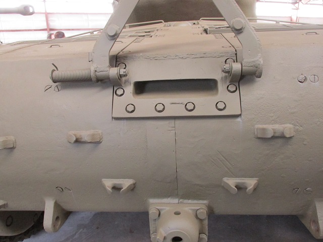
In order to adjust the track tension, first the plugs were removed in front of the idler bracket and the two jack screws were loosened. Inside the drivers' compartment, a lock clip needed to be swung out of the way after its top cap screw was removed. This would allow the serrated collar to be slid away from the idler shaft, freeing the shaft to turn. (Picture from TM 9-734 Medium Tank T23.)
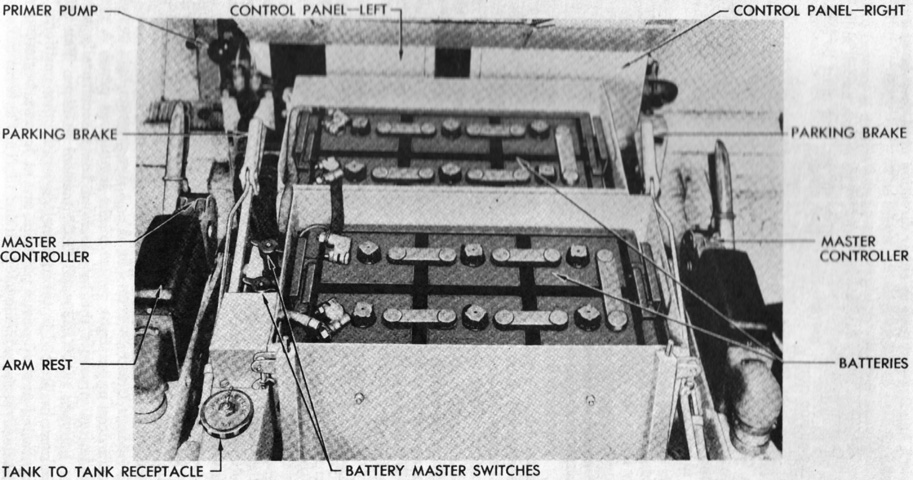
Two 12-volt lead-acid storage batteries were connected in series to create a 24-volt system. Each 180lb (82kg) battery had six cells with 25 plates per cell, for a 168 ampere-hour capacity. Each battery was mounted in its own box between the drivers' seats. (Picture from TM 9-734 Medium Tank T23.)
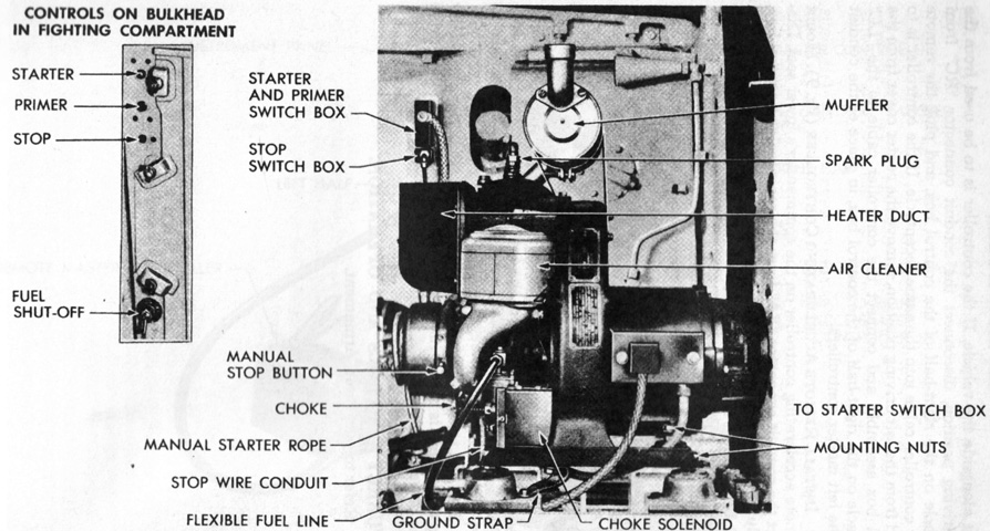
The auxiliary generator consisted of a 20-volt, 50-ampere (1,500 watt) generator driven by a 1-cylinder, two-cycle, air-cooled gasoline engine. The engine could be started electrically or manually by a pull rope. The assembly could be used to start the main engine, preheat the engine compartment, or charge the batteries and operate electrical accessories with the main engine off. It was shock-mounted at the right rear corner of the powerplant compartment, and had its own 5gal (19L) fuel tank built into the upper rear corner of the right fuel tank. Consequently, the right main fuel tank only held 87gal (330L) of fuel compared to the left fuel tank's 92gal (350L). (Picture from TM 9-734 Medium Tank T23.)
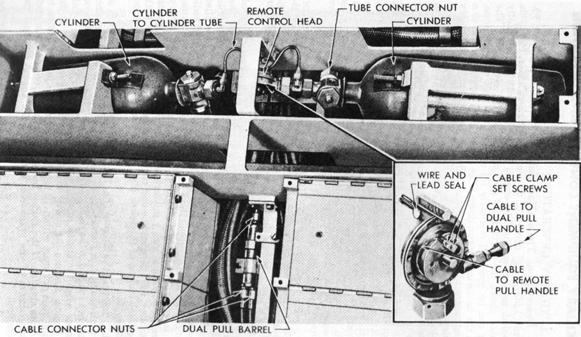
The fixed fire extinguisher system contained two 10lb (4.5kg) CO2 cylinders mounted on the hull floor just in front of the bulkhead. They discharged into six nozzles placed around the engine compartment, and could be actuated by control handles on the hull top behind the assistant driver's door or on the hull interior roof behind the driver's seat. The cylinders could also be discharged by removing the locking pins and rotating the handles in their control heads. (Picture from TM 9-734 Medium Tank T23.)
Though the 250 T23s built did not see active service, their direct descendant did. Fifty additional T23s were constructed with 90mm guns; ten of these were to be built with thicker armor and called T26. Further development and modifications including a more conventional powertrain and torsion bar suspension eventually yielded the T26E3, which was standardized as the M26 Pershing.
