
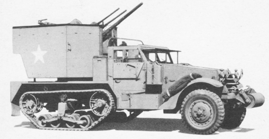
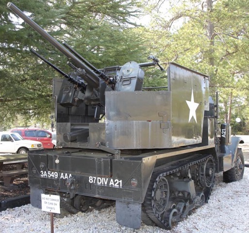
The combination gun mount M42 formed an imposing structure on the rear of the MGMC M15. The armor gun shield moved in elevation with the weapons, but the turret body was open to the rear. The gun shield was eventually deleted since it obstructed the gun crew's vision to an unacceptable degree. The guns could depress no farther than +20° above the cab and 0° for the rest of their traverse. The right side ammunition stowage box is visible between the cab and the turret. This half-track is fitted with the double coil spring loaded idler wheel, and the exhaust pipe can be seen in front of the track return roller. (Picture from Standard Nomenclature List G-102.)
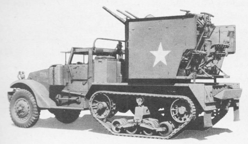
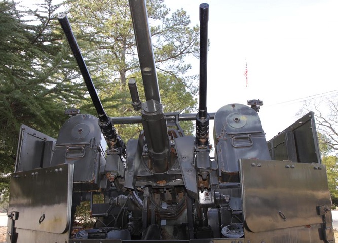
With the guns trained forward, it is easy to see how they would foul on the cab if below 20° elevation. (Picture from Tank Data, vol. 3.)
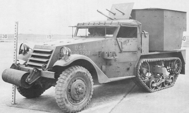
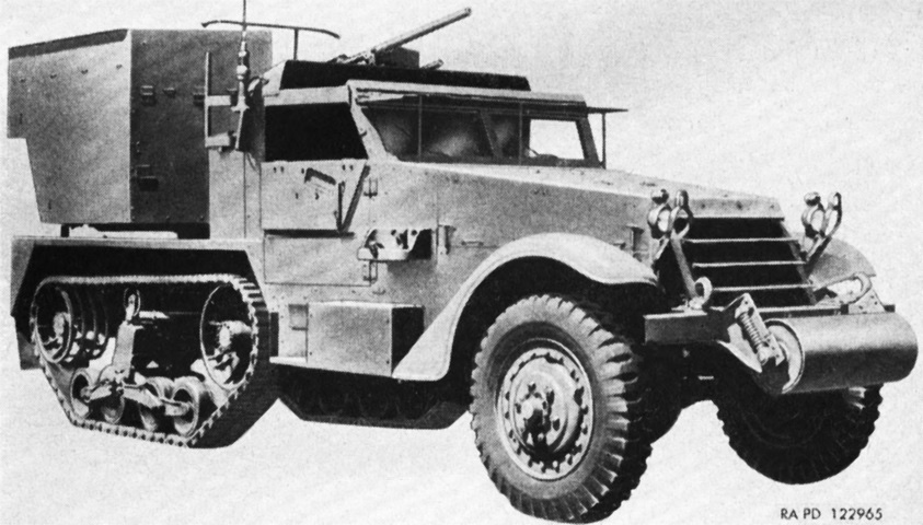
The gun shield has been removed from this machine. (Picture from TM 9-710 Basic Half-Track Vehicles (White, Autocar, and Diamond T).)
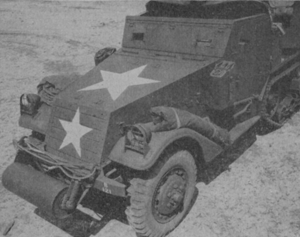
The armor for the windshield and doors has been emplaced, and the radiator louvres have been closed. The door armor flaps were held in place by rods, and before the windshield armor could be lowered the shatterproof glass and windshield wipers needed to be removed. The radiator louvres were controlled by the driver and had three positions between fully open and fully closed. (Picture from FM 4-159.)
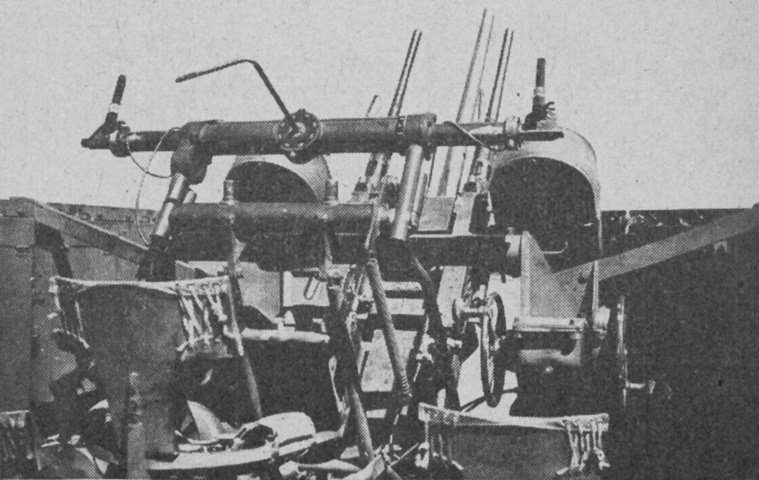
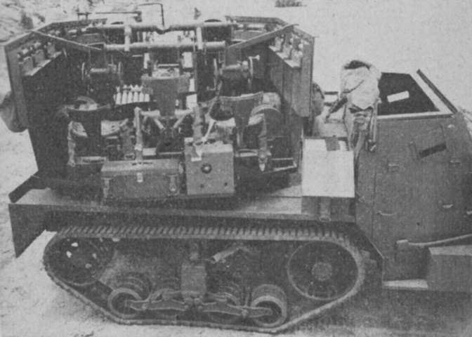
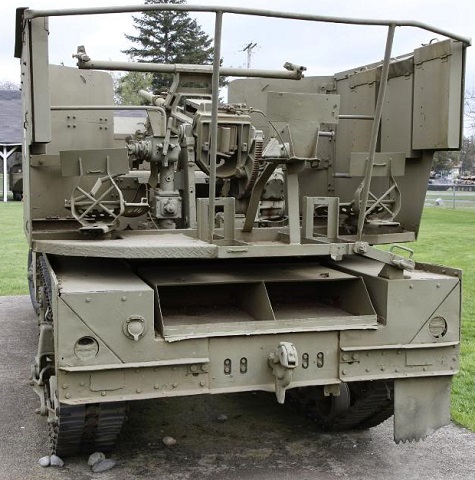
The open nature of the turret rear can be seen in this image. Three crew seats lined the rear turret opening. (Picture from TM 9-710 Basic Half-Track Vehicles (White, Autocar, and Diamond T).)
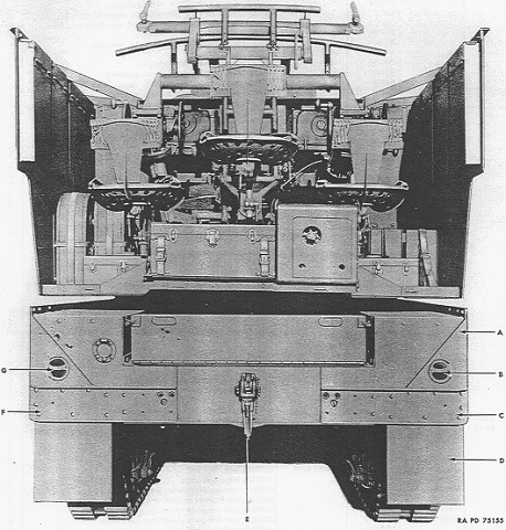
Details of the crew positions and rear of the vehicle can be seen here. A stowage compartment for .50cal ammunition was mounted right above the towing pintle. The letters refer to part numbers in the service parts catalog. (Picture from Standard Nomenclature List G-102.)
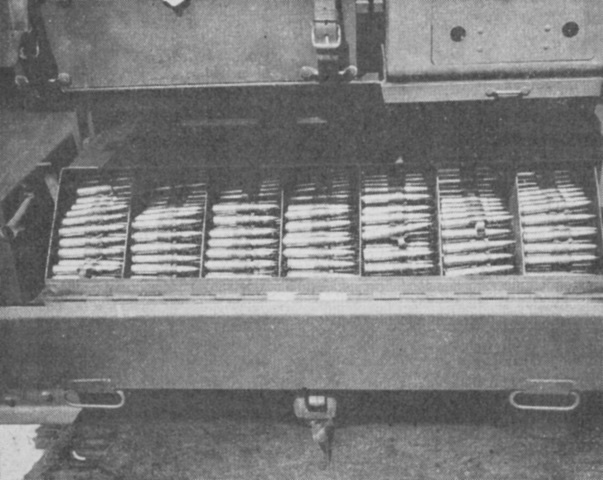
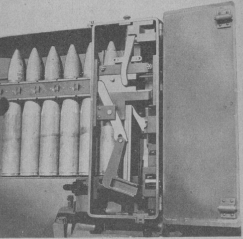
The machine gun ammunition stowage compartment is open here, showing placement of seven 200-round belts. Ten 200-round chests were stowed on the rotating platform in the fighting compartment. (Picture from FM 4-159.)
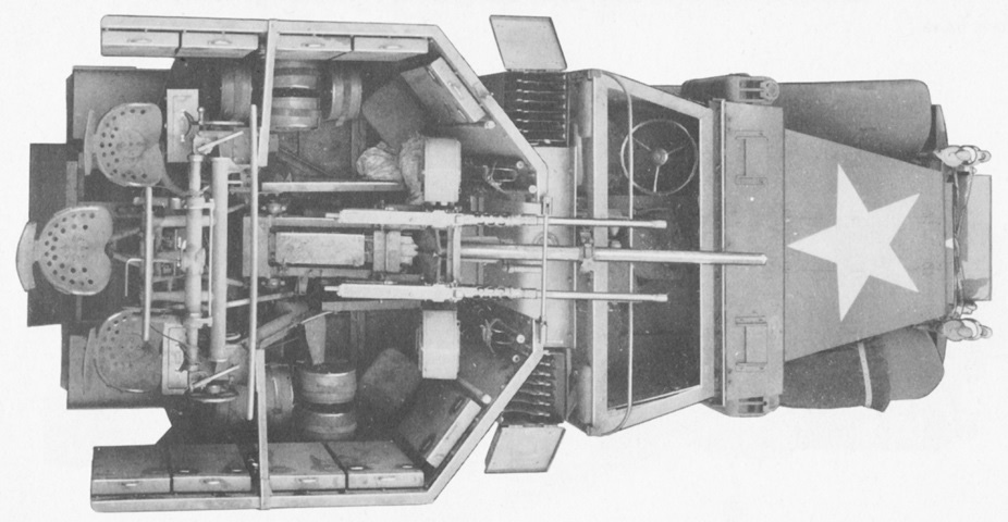
More details of the turret and crew positions can be seen here. An ammunition box was positioned on each side of the fuel tank behind the cab, and they are open in this image. (Picture from TM 9-710 Basic Half-Track Vehicles (White, Autocar, and Diamond T).)
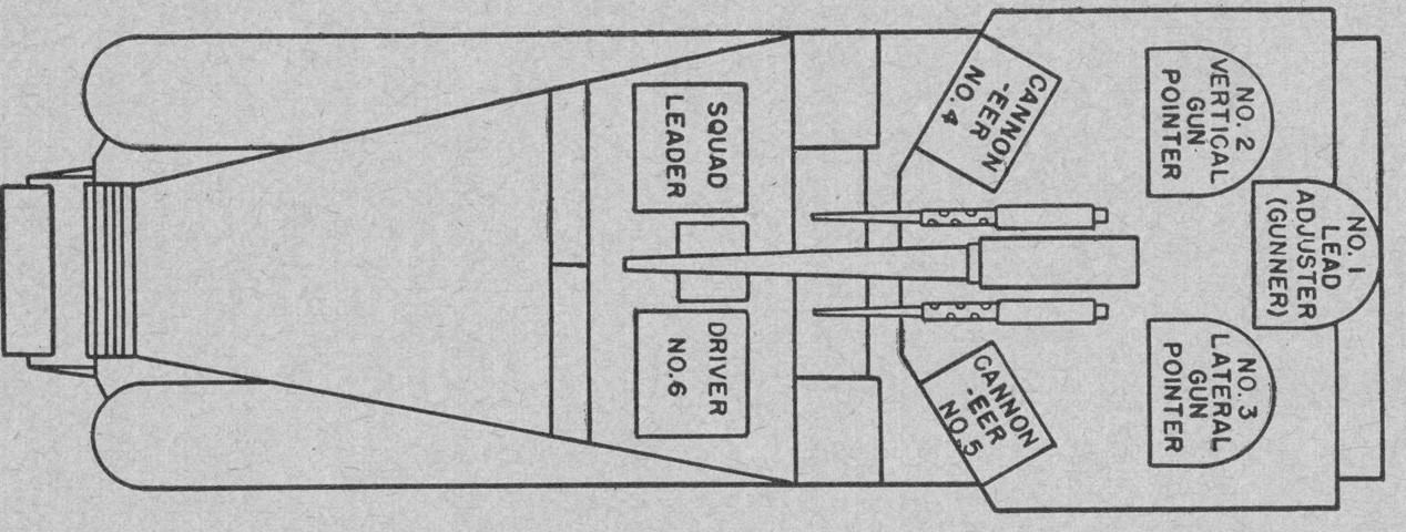
The crew positions are shown here. The driver operated the radio when the vehicle was halted and engaging targets; otherwise this was the commander's responsibility. The two cannoneers served the weapons, keeping the ammunition flowing and ensuring the guns were functioning. The gun pointers each had their own telescopes; keeping both eyes open and having their dominant eyes about one foot (30cm) from the telescopes were requirements. The vertical gun pointer had two foot pedals, the left one for firing the 37mm gun and the right one for firing the machine guns. The lead setter, who was the crew's second in command, applied leads to the sighting system and adjusted the tracer stream to obtain strikes on the target. (Picture from FM 4-159.)
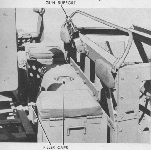
The fuel tanks in the M15 were relocated to directly behind the cab. The upper tank was just behind the drivers, while the lower tank was under the floor just behind the upper tank. The filler for the lower tank can be seen rising from the floor. Seat cushions were provided on the stowage boxes. (Picture from TM 9-710 Basic Half-Track Vehicles (White, Autocar, and Diamond T).)
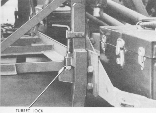
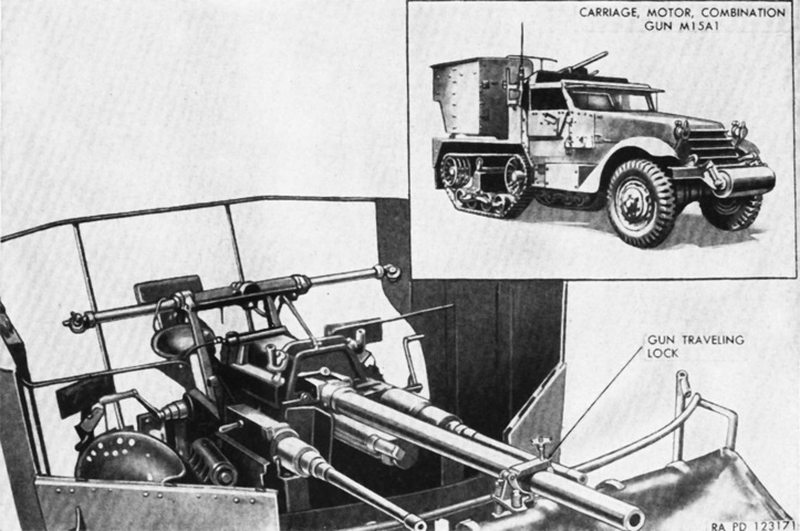
In addition to the gun support behind the drivers, two turret locks on the rear hull kept the turret in position while traveling. (Picture from TM 9-710 Basic Half-Track Vehicles (White, Autocar, and Diamond T).)
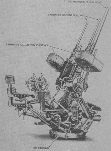
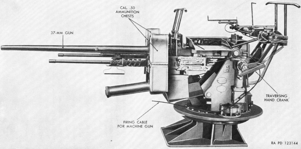
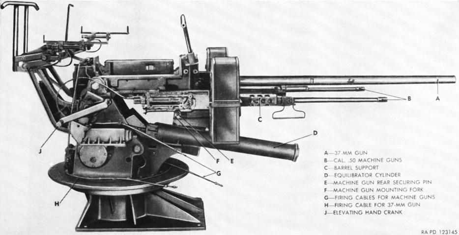
The combination gun mount M42 is shown here; the lower pedestal was secured to the vehicle, while the gun mount was attached to the upper pedestal. The elevation mechanism is visible on this side of the mount, with its two large handwheels with grab handles on opposite sides of the wheels. The elevation rate could be changed between two speeds by sliding the handwheels laterally along their axes. (Picture from FM 4-159.)
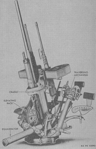
The traverse mechanism was found on the opposite side of the mount. Two speeds were obtainable by sliding the handwheels, like with the elevation mechanism. The slow speed moved the mount 3.75° for each complete turn of the handwheels, while the fast speed accomplished 11.25° for each turn. The spring-operated equilibrator mechanism visible in front of the mount balanced the handwheel load when the weapons were elevated or depressed. A rod attached the equilibrator to the rear of the gun cradle so that the spring compressed when the guns were lowered and was extended when the guns were elevated. (Picture from FM 4-159.)
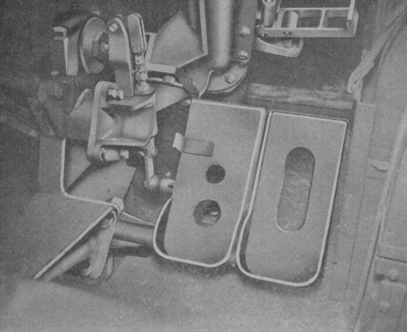
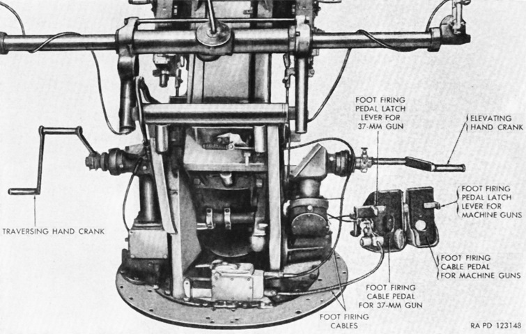
The foot pedals for the vertical gun pointer on the right side of the mount are shown here. The left pedal fired the 37mm gun, and the right fired the machine guns. The latch visible on the 37mm gun pedal needed to be disengaged by moving it to the left before the pedal could be depressed. When the 37mm pedal was released, the latch automatically reengaged the pedal. (Picture from FM 4-159.)
The sighting system M6 consisted of a telescope M7 on the left for tracking in azimuth, a telescope M64 on the right for tracking in elevation, a deflection mechanism for both vertical and horizontal deflection, and the support to mount these to the gun cradle. The 1x telescopes could be illuminated at night, and provided an 11° field of view. Deflection was accomplished by a single handle: turning it to the right or left set a right or left deflection, respectively, while pushing the handle up or down set a down or up deflection, respectively. It was important that the lead setter allowed his hand to ride with the deflection handle as the guns were elevated or depressed or else he could inadvertently change the vertical lead set-in. (Picture from FM 4-159.)
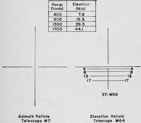
The reticle pictures of the sighting telescopes are sketched above. The M7 featured a continuous vertical crosshair that was used to track the target laterally, and a horizontal crosshair broken in the center. The M64 had a vertical center line and horizontal lines that denoted range in hundreds of yards, with the zero range line extending all the way across the field of view. The vertical center line was broken around the zero range line. The M64's range scale was derived from ballistic data of the 37mm gun M1A2 firing armor-piercing shot M59 at 2,050 feet/sec (625m/s), including the initial jump. (Picture from FM 4-159.)
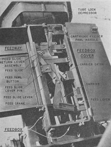
The 10-round clips for the 37mm gun were fed into the feed box from the left, and could be continuously loaded while the gun was consuming the previous clip. To keep the gun firing, just before the last round of the previous clip entered the feed box opening, the next clip was lightly pressed against the first clip until the pawl grasped the new clip. Expended shell cases were ejected from the bottom of the gun, and the clip from the right of the feed box. (Picture from FM 4-159.)
Ammunition is present in the feed box in this image. (Picture from FM 4-159.)
The stowage compartment for the 37mm ammunition is open in this image. The rounds were assembled into 10-round clips; 140 rounds were stowed in the boxes and 100 rounds were stowed on the gun shield. (Picture from FM 4-159.)
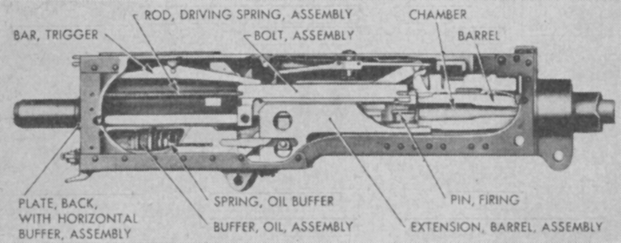
Interior parts of the M2HB machine gun are shown in this cutaway. The oil buffer was not filled with oil in the heavy barrel guns due to the higher weight of recoiling parts used in this model versus the water-cooled version. (Picture from FM 4-159.)
From this angle, the .50cal MGs are barely visible below the 37mm gun, marking this vehicle as an M15A1. (Picture from TM 9-710/TO 19-75A-77.)
A better view of the relationship between the machine guns and 37mm gun is provided here. (Picture from TM 9-710/TO 19-75A-77.)
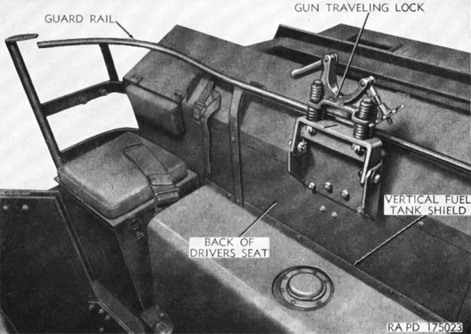
The guard rail and gun travel lock can be compared with those used with the mount M42. (Picture from TM 9-710/TO 19-75A-77.)
The combination gun mount M54 is shown here from the left. (Picture from TM 9-710/TO 19-75A-77.)
The opposite side of the gun mount is labeled. (Picture from TM 9-710/TO 19-75A-77.)
The elevating, traversing, and firing mechanisms are shown from behind the mount. Like the gun mount M42, the M54 used a two-speed traversing mechanism, and a shift lever was provided at the upper housing of the traversing mechanism. One turn of the handwheel rotated the mount 12° in slow speed and 24° in high speed. (Picture from TM 9-710/TO 19-75A-77.)
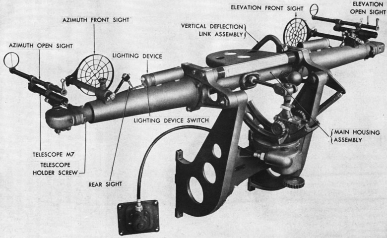
The computing sight M14 was composed of a support tube that reached across the rear of the gun mount, a computer, and an azimuth drive mechanism. A telescope M7, an open sight, and a direct fire sight were installed at each end of the support tube. The vertical deflection link assembly connected the sight's main body to the gun so that a parallel relationship with the gun was maintained during elevation. (Picture from TM 9-710/TO 19-75A-77.)
The sighting and fire control equipment is mounted. (Picture from TM 9-710/TO 19-75A-77.)
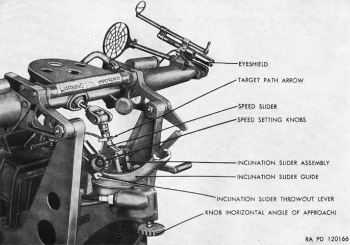
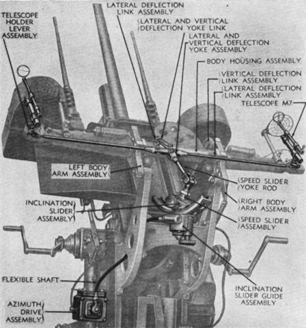
The target's estimated speed was inputted into the computer by speed setting knobs, which then caused the speed slider to move inside the inclination slider assembly until the index was opposite the correct speed value on the scale, which was graduated in 25mph (40kph) increments from 0 to 525mph (845kph). The target's horizontal path was entered so that a target path arrow was aligned with the target, and its vertical path by tipping the inclination slider in the appropriate direction. The target was then centered in the reticles of the azimuth and elevation telescopes. The computing sight could become locked at certain geometries of its armatures, and if not rectified these conditions could destroy the speed slider assembly. (Picture from TM 9-710/TO 19-75A-77.)
The turret is reversed on this vehicle, and the recuperator can be seen protruding from the armor under the guns. (Picture courtesy 8Hussar Ottawa.)
The hinged armor sections are folded down and are shown to good effect here. (Picture courtesy 8Hussar Ottawa.)
The large railing added to the gun mount to ease entry and exit is obvious when compared to the vehicles above. (Picture courtesy 8Hussar Ottawa.)
