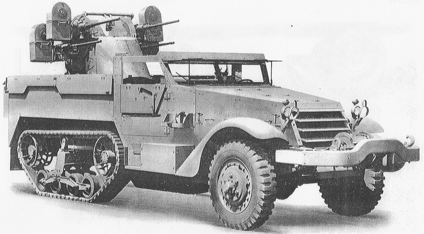
Multiple Gun Motor Carriage M16.
The M16 illustrated here is ready for fire with the armor flaps hinged down on the sides and rear. The notches in the side armor to allow free rotation of the turret can also be seen. (Picture from Standard Nomenclature List G-102.)

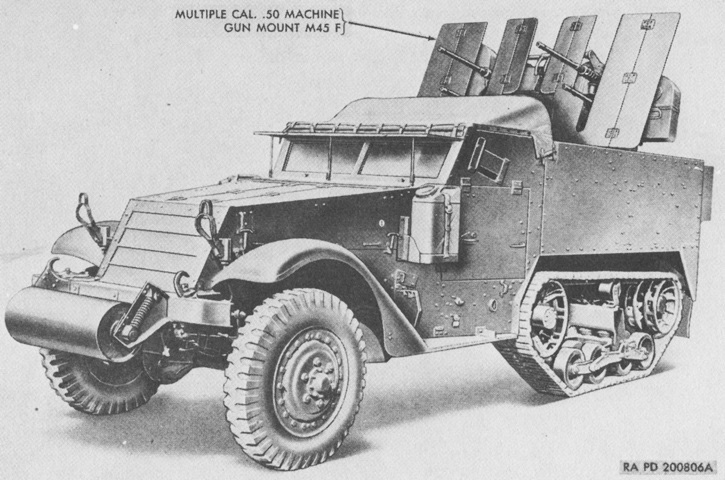
The rear door in the passenger compartment was not present, and stowage was mounted on the hull rear instead. (Picture from TM 9-710 Basic Half-Track Vehicles (White, Autocar, and Diamond T).)
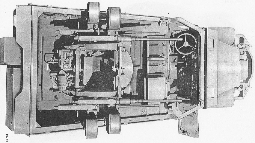
The gunner's position inside the turret can be glimpsed here, as well as how much room in the passenger compartment is taken up by the turret. Ammunition chests were stowed behind the driver's seat, although none are present in this image. (Picture from Standard Nomenclature List G-102.)
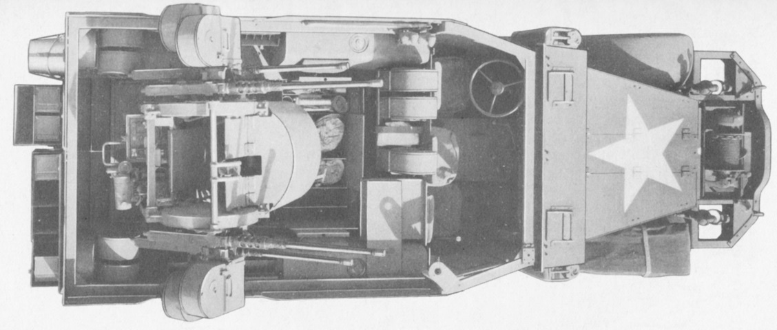
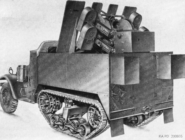
Ammunition chests are stowed on this vehicle, further reducing room in the rear compartment. (Picture from TM 9-710 Basic Half-Track Vehicles (White, Autocar, and Diamond T).)
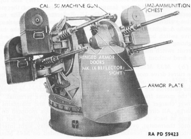
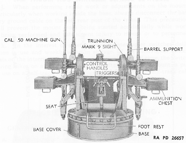
The multiple machine gun mount M45D is shown here with the armor plates in place to protect the gunner. Fully equipped, it weighed around 2,400lb (1,100kg), was 81.5" (207cm) wide overall, and 55" (140cm) tall with the guns at 0° elevation. Later-production M45s saw the addition of larger batteries (which retained the same 6-volt, 150 ampere-hours at 20-hour rate capacity); the replacement of the voltmeter with a hydrometer; a separate turret drive switch and circuit breaker, replacing the earlier combination turret drive switch and circuit breaker; and safety belts for the gunner. (Picture from TM 9-223 Twin Cal. .50 Machine Gun Mount M33 and Multiple Cal. .50 Machine Gun Mount M45.)
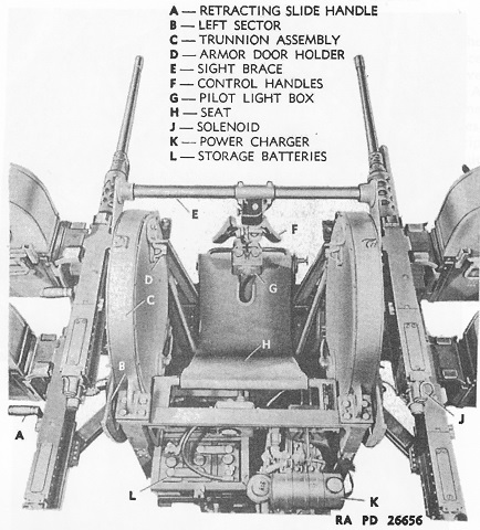
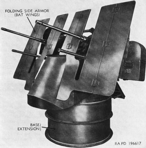
The M45D mount is seen here from the front with the guns elevated to 90°. The mount was 75" (190cm) tall in this configuration. (Picture from TM 9-223 Twin Cal. .50 Machine Gun Mount M33 and Multiple Cal. .50 Machine Gun Mount M45.)
This view is looking down into the gunner's seat. (Picture from TM 9-223 Twin Cal. .50 Machine Gun Mount M33 and Multiple Cal. .50 Machine Gun Mount M45.)
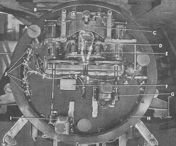
The power drive unit is revealed when seeing the gun mount from the bottom. A. Foot. B. Guard. C. Thermostat. D. Block. F. Relay. G. Elevation gear box. H. Turret ring gear. I. Azimuth gear box. J. Azimuth interrupter switches. (Picture from TM 9-223 Twin Cal. .50 Machine Gun Mount M33 and Multiple Cal. .50 Machine Gun Mount M45.)
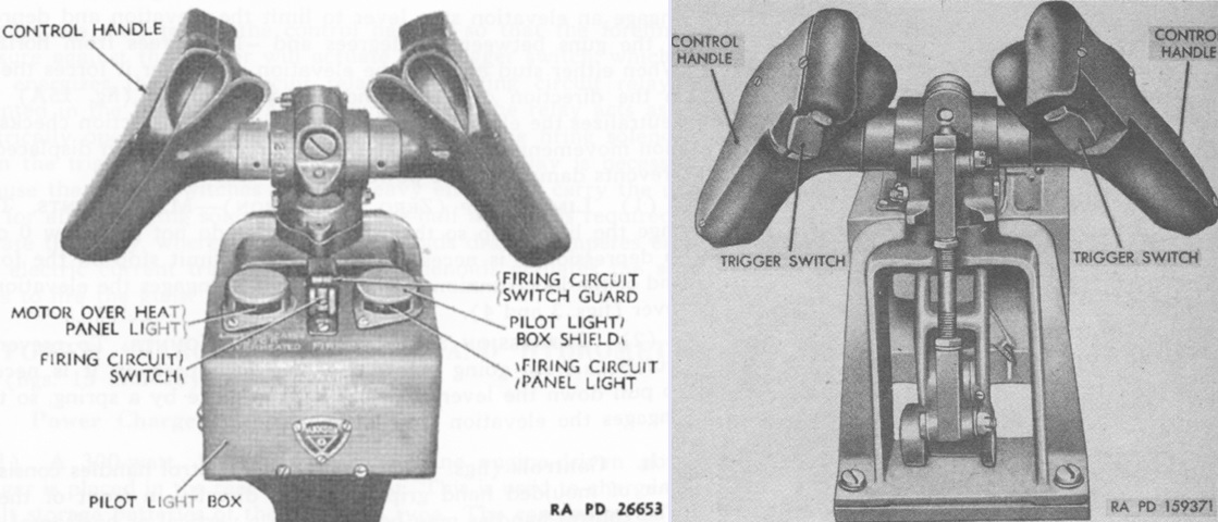
The gunner's control handles are shown from the front and rear, respectively. The motor over heat panel light would turn on when the motor reached 190-210°F (88-99°C). (Picture from TM 9-223 Twin Cal. .50 Machine Gun Mount M33 and Multiple Cal. .50 Machine Gun Mount M45 and TM 9-2010.)
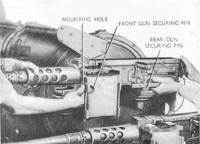
To mount the machine gun, it was slid backwards until the rear gun pin dropped into the horizontal slot in the horizontal adjustment block, then the gun was pushed forward until the hole in the forward end of the receiver lined up with the holes in the vertical adjustment yoke. The front gun securing pin was then twisted through the holes in the vertical adjustment yoke and gun receiver, and the gun securing pin latch was engaged to the front gun securing pin. (Picture from TM 9-223 Twin Cal. .50 Machine Gun Mount M33 and Multiple Cal. .50 Machine Gun Mount M45.)
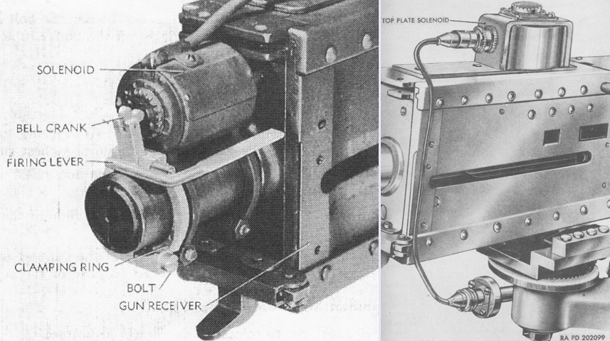
The original back plate solenoids B269179 (left) used to fire the guns were clamped onto the buffer tubes of the machine guns. Manual triggers were mounted behind the solenoids to enable the use of the guns without electrical power. Pressing on the trigger forced the solenoid core forward and fired the gun. The bell crank could be rotated away from the gun as a safety mechanism to prevent negligent discharges. Top plate solenoids 7162613 (right) eventually replaced the back plate solenoids. (Picture from TM 9-223 Twin Cal. .50 Machine Gun Mount M33 and Multiple Cal. .50 Machine Gun Mount M45 and TM 9-2010.)
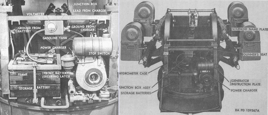
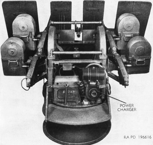
This rear view highlights the batteries and Briggs & Stratton Model 304 type 25592 power charger. The power charger was a 300-watt, 12-volt, one-cylinder 4-cycle gasoline engine that could be started either electrically or manually. As seen on the right, the voltmeter was eventually replaced by a hydrometer. The platform for the loaders of the M45D is also apparent in the right-hand image. (Picture from TM 9-223 Twin Cal. .50 Machine Gun Mount M33 and Multiple Cal. .50 Machine Gun Mount M45 and TM 9-2010.)
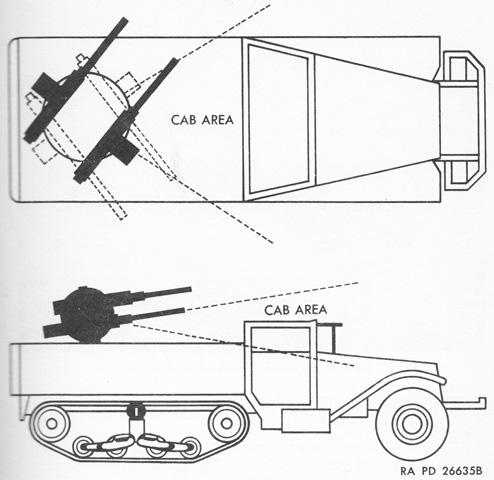
Interrupter switches in the gun mount prevented firing when the guns approached the vehicle cab. The limits were set in azimuth as from 56.5°±1° left traverse to 29.5°±1° right traverse for the bottom right-hand gun; 53°±1° left traverse to 33°±1° right traverse for the top right-hand gun; 22.5°±1° left traverse to 63.5°±1° right traverse for the bottom left-hand gun; and 26°±1° left traverse to 60°±1° right traverse for the top left-hand gun. In elevation, the restrictions were from the guns' lowest limit of depression to +4°±1° for the bottom guns and from the lowest limit of depression to -1.5°±1°for the top guns. Leaving the guns in the interrupted zone for long periods caused the springs in the interrupter switches to take a set, and the switches consequently would fail to function. (Picture from TM 9-2010.)
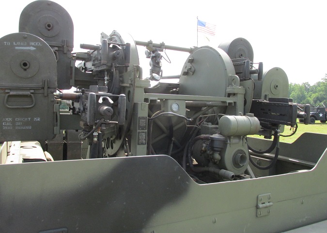
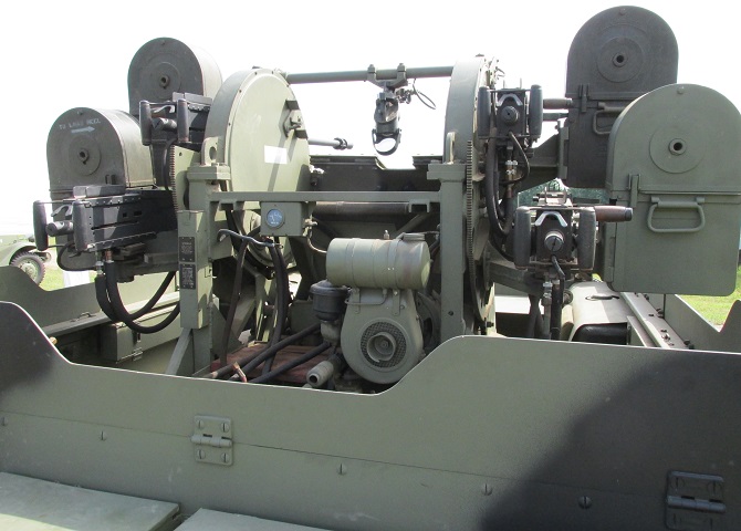
Details of the rear of the gun mount are provided here. Four two-hundred-round ammunition chests M2 fed the machine guns, and the hinged armor can be seen as well. Note that this vehicle has been fitted with flexible-type machine guns.
With the gun mount taking up so much room in the rear, the vehicle's fuel tanks were relocated to the front of the passenger compartment. The right-side fuel tank with its filler cap on top can be glimpsed towards the front of the vehicle.
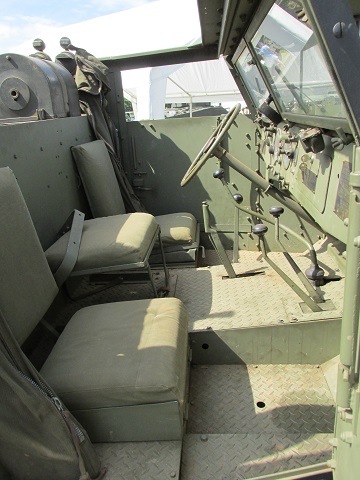
Three seats were still provided in the driver's area. Stowage for spare ammunition chests can be seen behind the seats. From foreground to background, the floor-mounted levers are the front drive shift lever, the transfer case shift lever, the (very long) transmission shift lever, the parking brake lever (the only lever without a black knob), and the power take-off shift lever. The power take-off lever operates the winch: when pushed forward the winch reverses to unwind cable and when pulled to the rear the winch operates in forward speed to wind the cable. The vehicle's clutch was depressed before moving the power take-off lever, and when the clutch was released the winch speed was controlled by the vehicle's foot accelerator pedal.
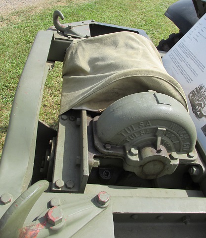
The mounting of the front winch is shown here.
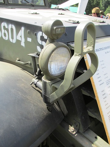
A closeup of the later, small demountable headlight is provided in this image. A marker light is mounted above the headlight. When the headlight assembly was dismounted, a plug chained to the mounting bracket filled the resulting hole, protecting it from debris. Half-tracks manufactured by International Harvester also used demountable headlights, but the brush guard was of a different design.
This machine lacks the folding passenger compartment armor panels found on the custom-made antiaircraft half-tracks, but the quad-machine gun turret was raised 6" (15cm) to enable the weapons to fire over the sides and rear of the half-track. The folding shields for the gun crew are deployed. Elevation interruption for the M45F was changed: for the lower guns it was from the lowest limit of depression to 0°±1°, and for the upper guns it was now from the lowest limit of depression to -5.5°±1°. Azimuth interruption was unchanged from the M45D. (Picture from TM 9-2010.)
Since the M16A1 featured a rear door, stowage on the rear armor was rearranged so that it was not blocked. Coverage of the passenger compartment by the folding shields can be gleaned as well. (Picture from TM 9-710/TO 19-75A-77.)
The base extension allowed the multiple machine gun mount M45F to deliver ground fire over the cab and sides at closer ranges. In addition to the riser and the folding shields, the mount M45F incorporated a slip ring for the intercom system that connected the gunner, the squad leader in the cab, and a field telephone connection at the motor carriage's rear; and wiring that enabled two-way power between the vehicle generator and the gun mount battery, and between the gun mount power charger and the vehicle battery. This two-way circuit was controlled by a switch on the mount accessible to the gunner. The M45F weighed around 2,900lb (1,300kg). (Picture from TM 9-710/TO 19-75A-77.)
Gaps were necessarily left in the shields to provide for the gun barrels' elevation and the gunner's sightline. (Picture from TM 9-710/TO 19-75A-77.)
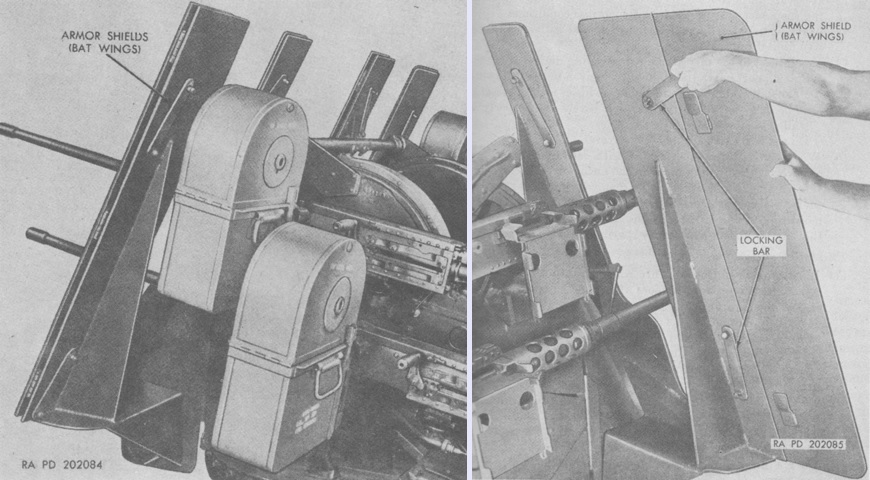
The armor shields are shown folded on the left and in the process of deployment on the right. Locking bars ensured the shields remained in the open position. The mount could be operated with the shields in the folded position. (Picture from TM 9-2010.)
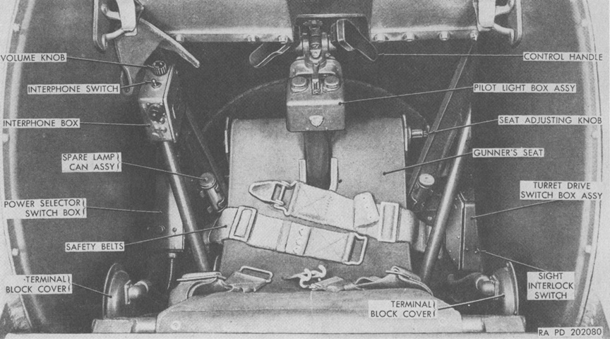
The controls of the mount M45F are labeled here. The power selector switch box and interphone switch were new to the M45F. The power selector switch box had a charger switch and a power supply switch that enabled power to be provided from either the vehicle battery or from the mount battery while the vehicle battery was charging. It also allowed the vehicle battery to be charged by running the gun mount if the half-track battery was dead, and similarly to charge the half-track battery while simultaneously using it to supply power. (Picture from TM 9-2010.)
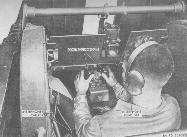
The gunner is shown at the mount controls with the interphone headset in position. The interphone allowed communication between the gun mount and half-track, and also radio contact from outside sources. (Picture from TM 9-2010.)
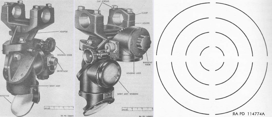
The original reflector sight Mk. 9 was replaced by the reflex sight M18, seen on the left and in the center respectively from the right rear and right front. The M18 was a projection-type collimator sight that could use sunlight or artificial illumination when desired. The artificial illumination was provided by the housing assembly, shown lowered on the left and raised in the center image. When raised, daylight was allowed to pass into the sight. Its reticle, sketched on the right, consisted of four lead circles. The 65-mil circle corresponded to 100mph (160kph), the 130-mil circle to 200mph (320kph), the 195-mil circle to 300mph (480kph), and the 260-mil circle to 400mph (640kph). Three sighting dots were also used but are not present in the drawing. The top dot was used for determining the line of sight, while the lower two, with one at 5 mils elevation and the other at 10 mils elevation, were used for superelevation. (Picture from TM 9-2010.)
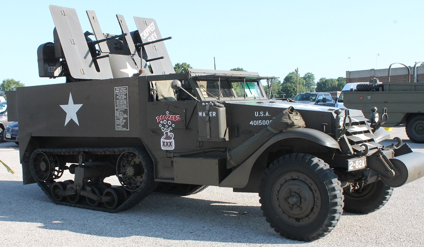
This MGMC M16A1 also illustrates features of the M3 half-track, like fenders that are thick in cross-section and bolted armor. Notice also the late, double-coil spring-loaded idler wheel. This machine lacks the folding passenger compartment armor panels found on the custom-made antiaircraft half-tracks, but the quad-machine gun turret was raised 6" (15cm) to enable the weapons to fire over the sides and rear of the half-track. The driver's armored door cover is folded down, and the armored windshield cover is elevated. The folding shields for the gun crew are readily visible, and the inner shields are folded onto each other. (Photo by Richard S. Eshleman.)
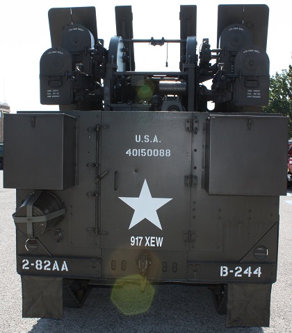
The rear door was retained, and the inner shields are folded onto each other. (Photo by Richard S. Eshleman.)
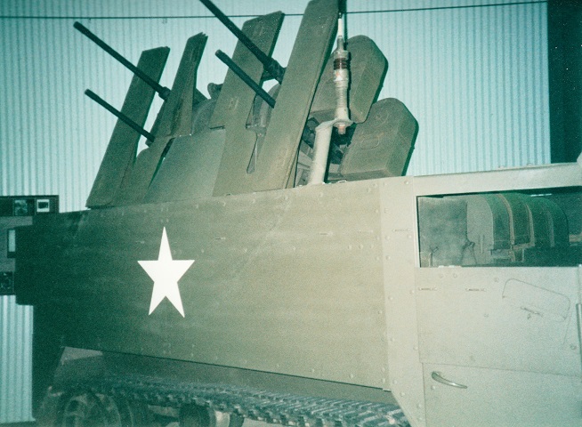
The outer sections of the "bat wing" shields on this MGMC M16A1 are folded inward and resting on the inner plates.
