Heavy Tank Mark VIII.
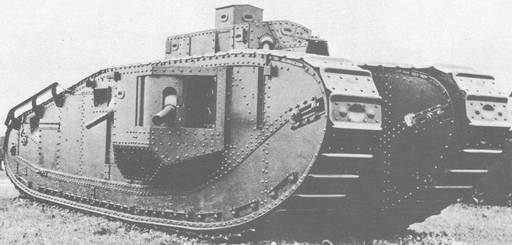
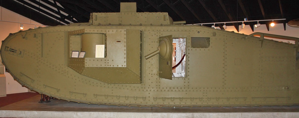
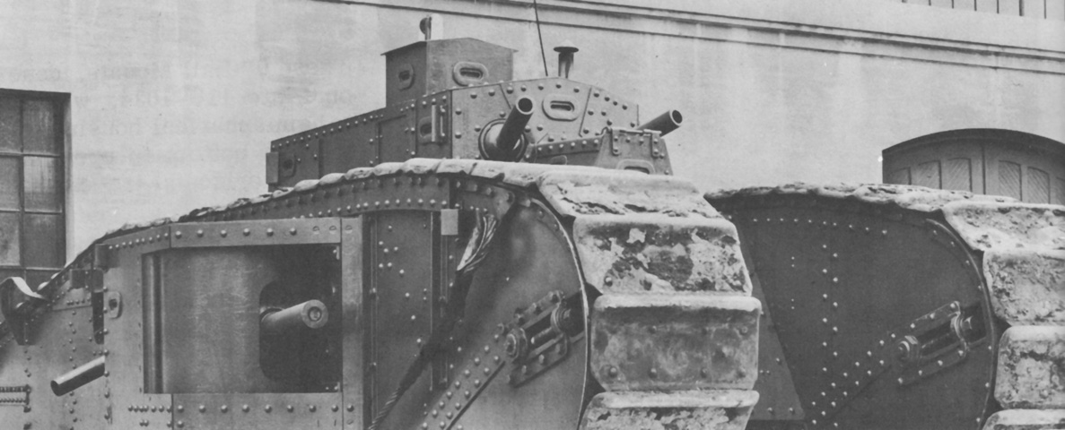
The rhomboid shape of the Mk. VIII's track frames resembled previous British landships. The 6 pounder guns were located in the sponsons, as in earlier designs, and behind each sponson was a door that mounted a .30cal MG. The longitudinal line of rivets that runs under the sponson shows the outline of the hull, which itself is hidden between the tracks. The screw mechanism for the road-track adjusting wheel (i.e., idler) can be seen at the front of this line of rivets. The commander's boxlike lookout turret can be seen resting atop the nonrotating main turret. The structure above the rear tracks was the unditching gear strut, and the apertures along the upper run of the track to the rear were mud deflection chutes. Note that the plate directly below the lookout turret is hinged at the top and is slightly ajar in this image. (Picture from Tank Data, vol. 1.)
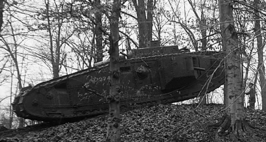
The imposing size of the Mk. VIII can be gleaned by comparing it to the man standing in front of the tank on the hill's reverse slope. (Picture taken in 1921-3 by Harris & Ewing, Inc.; available from the Library of Congress.)
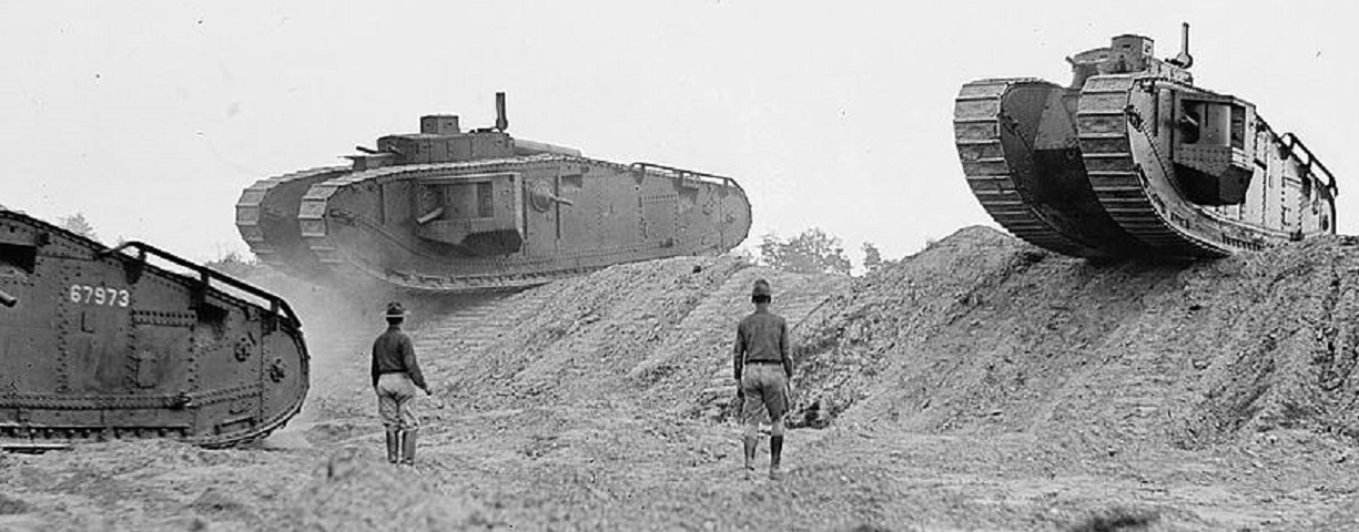
These tanks are taking part in a demonstration. Of interest are the colored semaphore signals mounted to the left rear of the turrets, which can be better seen in this image versus the picture above. (Picture taken in 1922 by the National Photo Company; available from the Library of Congress.)
The tanks driving toward the soldiers in the above image would certainly present an impressive view from the ground.
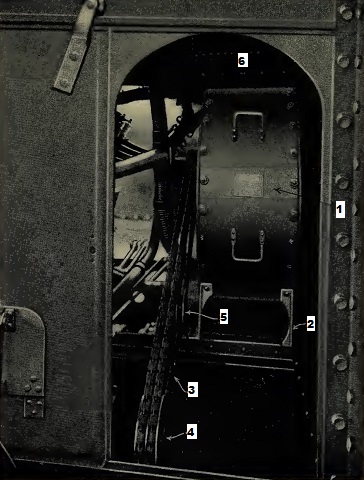
The upper rear hull is illustrated here. 1. Roof towing bracket. 2. Inlet louver. 3. Exhaust pipes. 4. Filter pipe for water-cooling system. The intake louver aperture was 37.25" (94.62cm) wide and 25.825" (65.596cm) long, and the 34 louvers were bars of 2.5"- (6.4cm-) wide, 6mm- (.2"-) thick armor bent to 90° and spaced face to face herringbone style. Above the radiator could be found a 37.25"- (94.62cm-) wide by 37.625"- (95.568cm-) long exhaust louver aperture protected by 29 similar louvers. Each set of louvers was between a set of two 6mm (.2") flanged steel bars that rose 8.75" (22.2cm) above the hull roof. (Picture from Preliminary Handbook of the Mark VIII Tank.)
In contrast to the above handbook image, production tanks accepted by the US Army had engine exhaust pipes that ran the entire length of the rear deck. No mufflers were fitted.
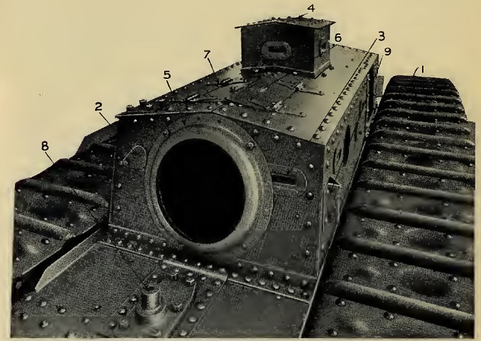
The forward upper rear hull and turret rears are the subject of this image. 1. Road track. 2. Revolver port cover. 3. Peephole. 4. Outlook turret. 5. Cover plate for hemispherical turret. 6. Main turret roof doorplate, starboard. 7. Main turret roof doorplate, port. 8. Roof towing bracket. 9. Camouflage net support socket. The door on the turret roof was 20" (51cm) long and 15.785" (40.323cm) wide. (Picture from Preliminary Handbook of the Mark VIII Tank.)
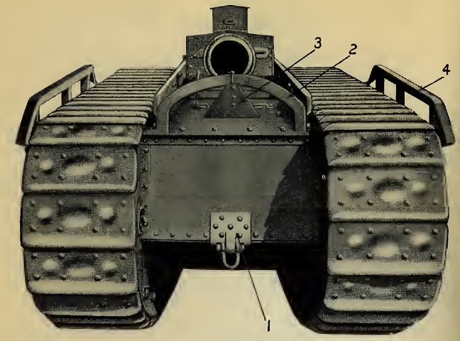
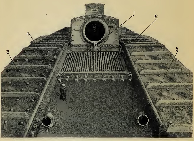
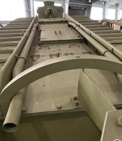
The rear of the tank and towing gear are shown in this image. 1. Towing bracket. 2. Stern guide for haulage rope. 3. Deflector plate. 4. Rear strut unditching gear. (Picture from Preliminary Handbook of the Mark VIII Tank.)
The attachment of the triangular splash deflector plate is highlighted, along with details of the exhaust pipes and engine louvre covers.
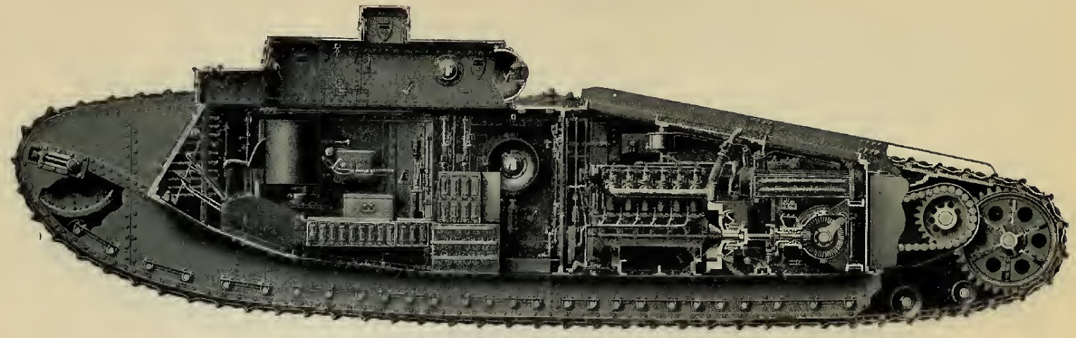
A cross-section of the vehicle is provided here. The large road-track adjusting wheel can be seen at the front; the driver's seat is at the front of the fighting and operating room, as the crew compartment was called; the engine is separated by a bulkhead; followed by the gearbox and chain-driven roller sprocket and track driving sprocket. The engine room was 9'9" (3.0m) long. On the floor below the lookout turret can be seen the officer's kit box, on which the commander stood to see out of the lookout turret. (Picture from Preliminary Handbook of the Mark VIII Tank.)
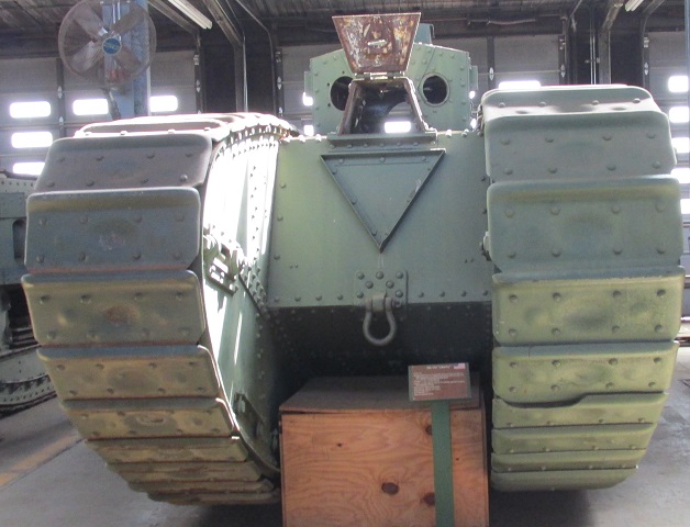
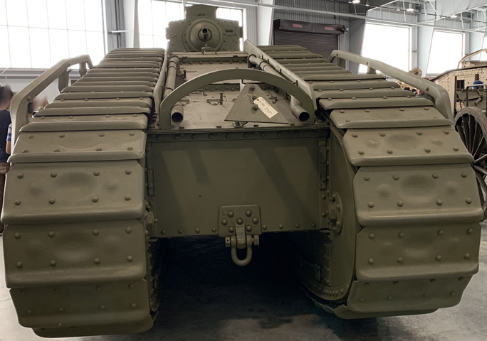
The door in the driver's turret is open, and the machine gun mounts flanking the driver in the main turret are absent. The large triangular bullet splash angle is apparent on the front of the hull, and a towing bracket hangs beneath.
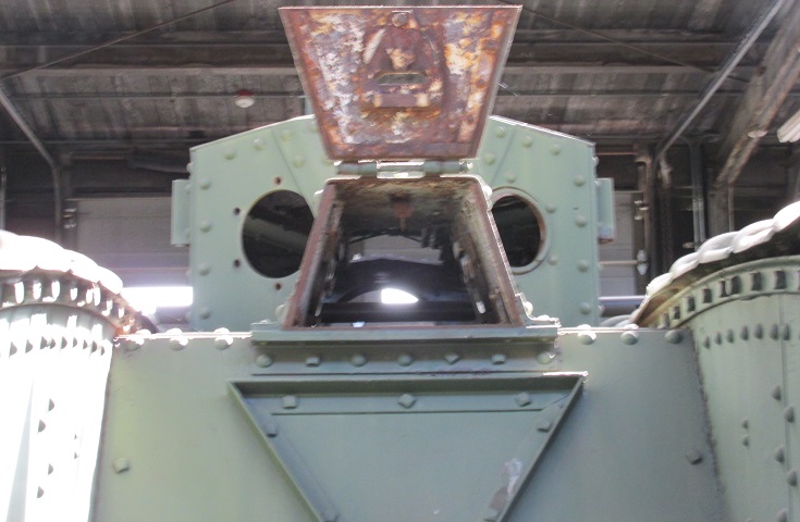
A closer view of the open driver's turret is provided here. The small fixtures on each side of the main turret outboard of the machine gun mount apertures are camouflage brackets.
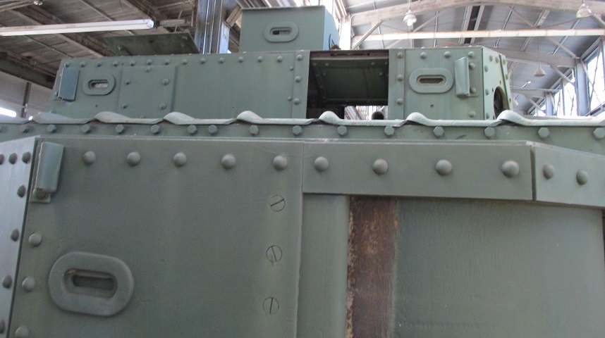
The right side of the main turret and commander's lookout turret are the focus of this image, and the right sponson dominates the lower half of the picture. Camouflage brackets were mounted on each corner of the turret as well as on the sponsons. The hinged armor plate in the main turret is more easily seen here since it is open farther than in the picture above.
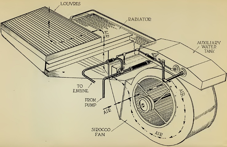
The cooling system is shown schematically here. (Picture from Preliminary Handbook of the Mark VIII Tank.)
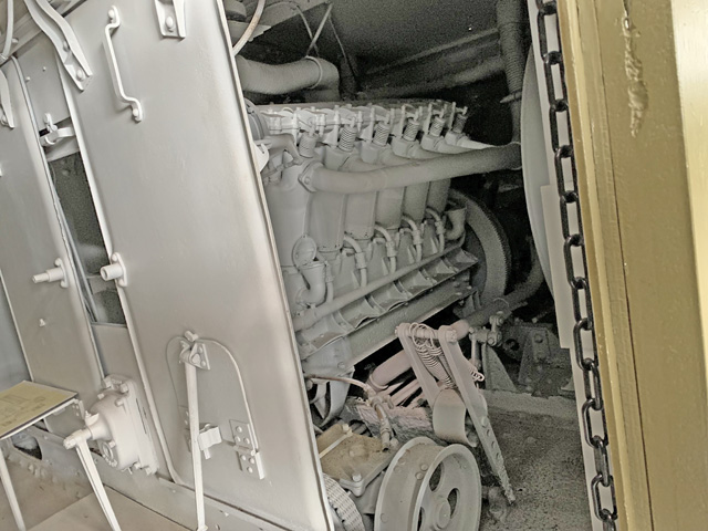
The Sirocco fan for the cooling system is shown installed here. The fan would draw air in through the roof intake lovers and send it through the engine radiator behind the fan. The fan's capacity was 11,000ft³ (310m³) of air per minute. 1. Large fan. 2. Fan support. 3. Whittle belt. 4. Driving pulley (fan bevel box). 5. Jockey pulley. 6. Water tank. (Picture from Preliminary Handbook of the Mark VIII Tank.)
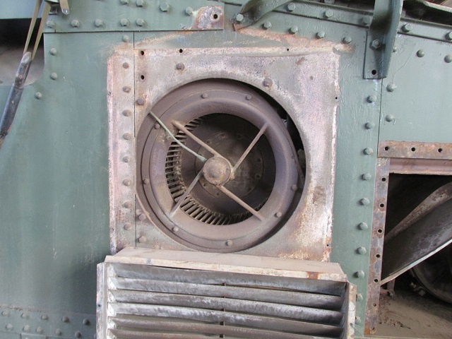
The mounting of the fan on this example has been modified from the original design.
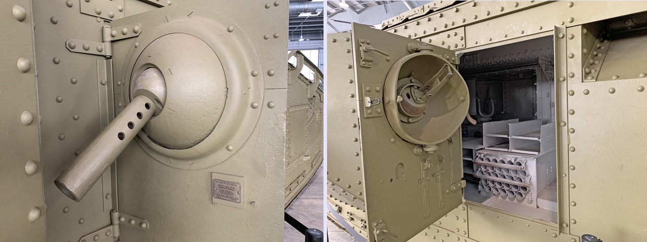
A closer view of the side of the vehicle is shown here. The sponson gun is not mounted, but the location of the side door machine gun ball mount can be seen, and the machine gun positions in the turret can just be glimpsed immediately above the track. The side doors were 28.5" (72.4cm) wide and 41.875" (106.36cm) tall. A peep hole was placed in the sponson behind the gun; these slots had visors with three different protection levels. (Photo by Richard S. Eshleman.)
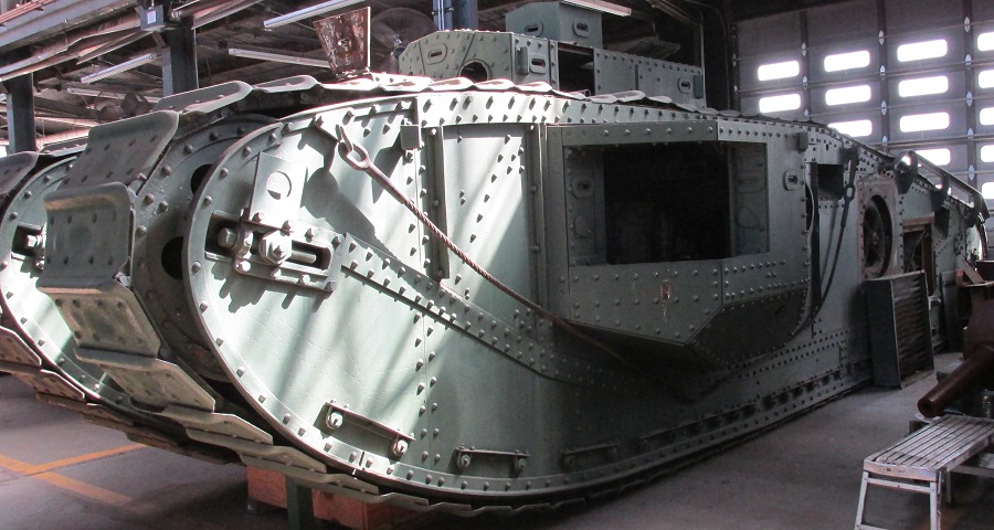
The 6 pounder has been removed from this tank, which better allows the peep holes and revolver holes on the sponson to be seen. Note that the road-track adjusting wheel has been moved forward compared to the tank above.
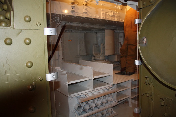
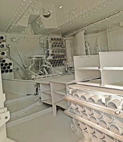
This image was taken through the open right side door, looking diagonally forward into the tank. The left-side sponson gun mount can be seen, as well as the peep hole behind it. The mannequin is standing up in the turret, and copious ammunition stowage is apparent under the floor and under the sponson gun mount opposite. (Photo by Richard S. Eshleman.)
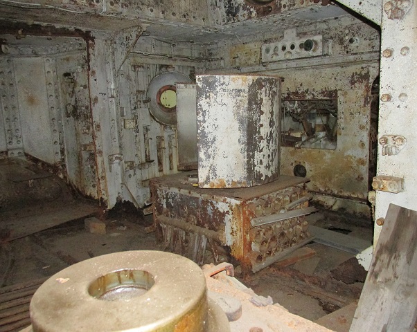
This view is looking toward the right rear of the fighting compartment. A sponson gun shield rests on an ammunition rack, a space normally occupied by racks for machine gun ammunition. The engine compartment bulkhead with its missing vertically-sliding center door can be seen behind this. Two side doors carried by rollers were also integrated into the bulkhead. The right-side sponson juts outward, and behind this can be seen the door with the round machine gun mount. Above the aperture for the sliding door to the engine compartment is the instrument board, which contained the oil gauge, a gauge for each of the three three gasoline tanks as well as the auxiliary gasoline tank, a tachometer, and a yardometer.
Looking forward to the right front, the driver's position is visible. His seat is flanked by four control levers: two speed control levers to the inside that changed the transmission ratios, the clutch lever to the outer left, and the reverse lever to the outside right. Spark and throttle levers were mounted on the front wall in front of the driver to his left and right, respectively, and a track brake pedal was placed between the speed control levers. Racks for 6 pounder ammunition flanked his position to the front.
This image is looking up into the rear of the main turret. Ball machine gun mounts are visible in the turret rear as well as the green door opposite the camera. Sliding doors for the engine compartment are present on this machine.
Another view of the driver's position is shown here. The driver could shift from high to low gears without using the clutch lever, but pulling the clutch lever was a necessity before using the reverse lever. Steering was accomplished by shifting one track into low or neutral gear while keeping the opposite in a higher gear. Turns could be made tighter by using the brake pedal which, due to a swing link connecting with the shifter levers, only affected the tracks when they were shifted to neutral; when both tracks were in neutral the brake could be applied to both. (Picture from Preliminary Handbook of the Mark VIII Tank.)
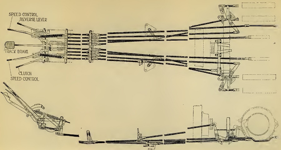
The driver's controls and linkages are diagrammed here, with the exception of the spark and throttle levers. (Picture from Preliminary Handbook of the Mark VIII Tank.)
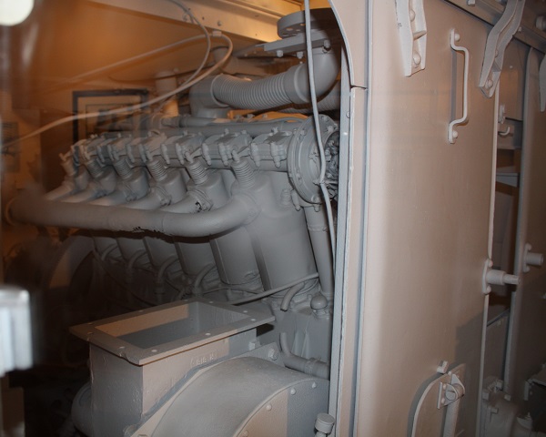
The tank's engine was provided with a bulkhead, as opposed to earlier rhomboid designs, and this picture is shot through an opening in the bulkhead. The 900ft³/minute (25m³/minute) fan for the ventilation system is to the left of the engine in this image, and the fan's vertical attachment to the missing inlet ducting is below the engine's exhaust manifold. The dual overhead camshaft engine's hand crank mounting can be seen at the extreme bottom right of the photograph. The engine cylinders had a 5" (13cm) bore and a 7" (18cm) stroke for a displacement of 1639.34in³ (27027.7cm³). It was governed to 1400rpm. (Photo by Richard S. Eshleman.)
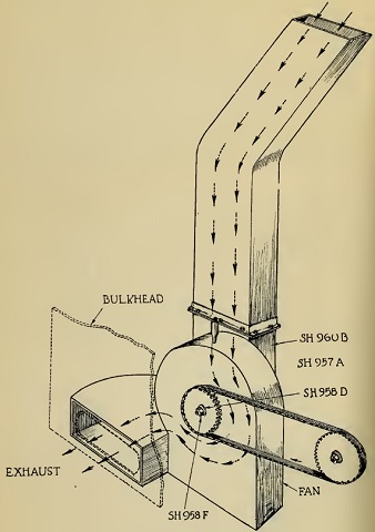
The ventilation fan is sketched here from the opposite side with the ducting intact. (Picture from Preliminary Handbook of the Mark VIII Tank.)
A view at the opposite side of the engine compartment is shown here. The shroud for the Sirocco cooling can can be seen to the right. Liberty engines intended for aircraft use were not significantly different from the tank version: a flywheel was installed on the tank engine, shafts were added to help increase oil flow to the connecting rod bearings, and a tie was welded between the intake and exhaust elbows to help prevent cracks in the cylinder jacket.
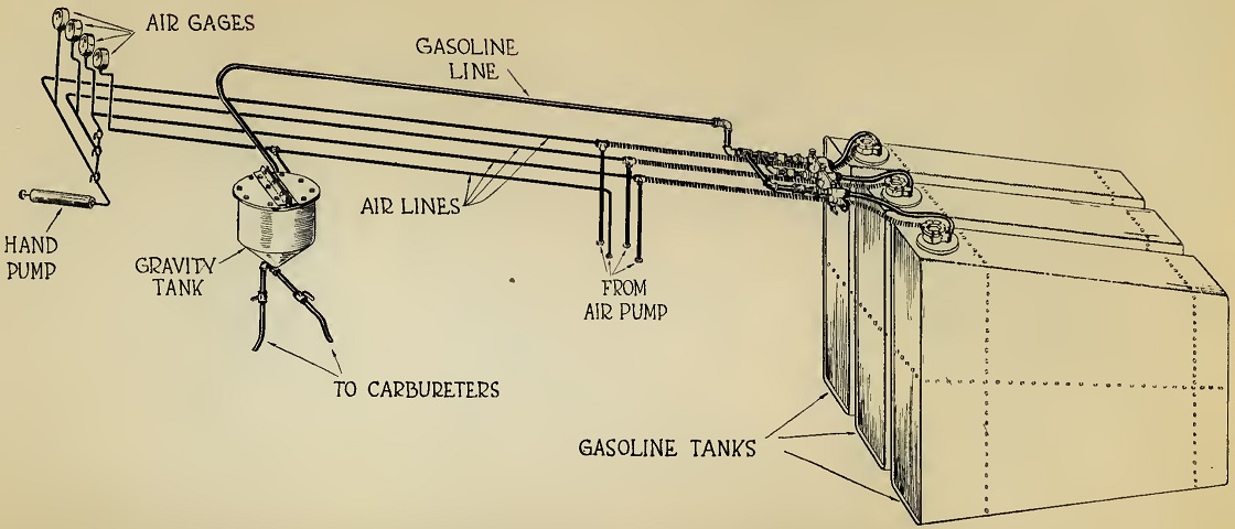
The fuel system is diagrammed in this drawing. Three 80gal (300L) tanks were installed at the rear of the vehicle, separated from the engine room by a bulkhead. An engine-driven air pump forced gasoline from these tanks into a gravity tank above the engine, from which fuel flowed into the two carburetors by gravity. A hand pump was provided to start the flow of gasoline. (Picture from Preliminary Handbook of the Mark VIII Tank.)
The gasoline tanks are mounted in this picture. 1. Petrol tank. 2. Port cover for petrol tank. 3. Starboard cover for petrol tank. 4. Petrol tubes from tank to combination tap. 5. Air-pressure tubes tank to combination tap. 6. Filling cap. (Picture from Preliminary Handbook of the Mark VIII Tank.)
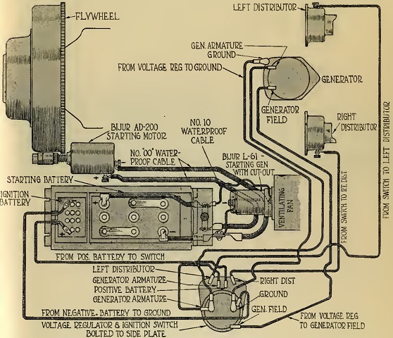
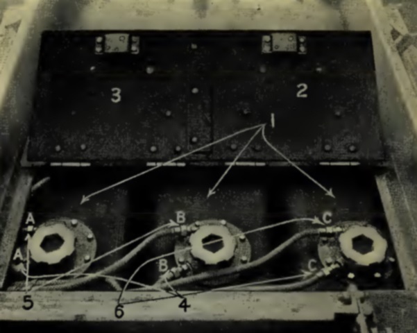
The wiring for the lighting, starting, and ignition is diagrammed. A 6-volt, 140 ampere hour battery powered the starting motor, although when cold the starting motor needed help from the engine's manual hand crank. (Picture from Preliminary Handbook of the Mark VIII Tank.)
This removed panel allows a look into the engine compartment. The engine is to the right of the image, and in the background the compound clutch and clutch stop drum can be seen working back to the epicyclic transmission. A cross shaft carried the power through the large track brake to the driving sprocket chain, which spun the chain sprocket to the rear, which finally engaged the road-track driving wheel via roller bearings.
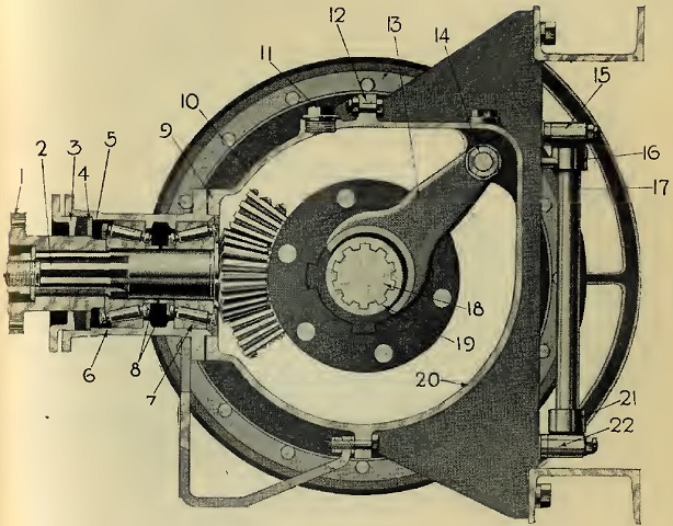
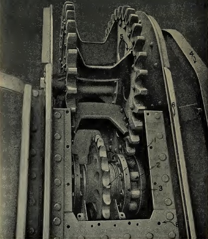
The epicyclic drive is diagrammed in this image. 1. Flange coupling for bevel-pinion shaft. 2. Bevel pinion and shaft. 3. Stuffing-box gland. 4. Oil-retaining washer for stuffing box. 5. Stuffing-box disk. 6. Stuffing box and Timken bearing casing. 7. Timken bearing. 8. Distance piece for bevel-pinion shaft. 9. Packing washers for bevel-pinion adjustment. 10. Bevel-gear case cover. 11. Oil-filling cap. 12. Joint for bevel-gear case. 13. Clutch fork for reversing gear. 14. Striking rod for reversing gear. 15. Vertical shaft bearings for reversing gear. 16. Top lever for reversing gear. 17. Vertical shaft for reversing gear. 18. Bevel and epicyclic cross shaft. 19. Clutch for cross shaft. 20. Bevel-gear case. 21. Bottom lever for reversing gear. 22. Vertical shaft bearings for reversing gear. (Picture from Preliminary Handbook of the Mark VIII Tank.)
An exterior view of the epicyclic transmission is shown. (Picture from Preliminary Handbook of the Mark VIII Tank.)
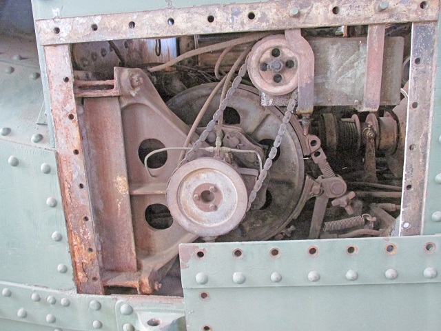
A closer look reveals the large driving sprocket chain in more detail as it wraps around the 12-tooth sprocket just outboard of the track brake.
The roller pinion and track drive are isolated in this picture. 1. Chain sprocket and roller pinion. 2. Roller. 4. Guide rail. 5. Road track driving wheel. 6. Upper track rail.
The drive from the epicyclic gear on each side of the tank was transmitted to the track by a chain which was looped around the driving sprocket on the epicyclic cross shaft and the roller pinion which meshed with the road-track driving wheel. The chain sprocket of the roller pinion had 23 teeth. The maximum working load of the driving chains was 53,000lb (24,000kg) and their breaking load was 150,000lb (68,000kg). The outside bars of the chains were .5" (13cm) thick, while the inner bars were .625" (1.59cm) thick. The chain is not present in the illustration for clarity. (Picture from Preliminary Handbook of the Mark VIII Tank.)
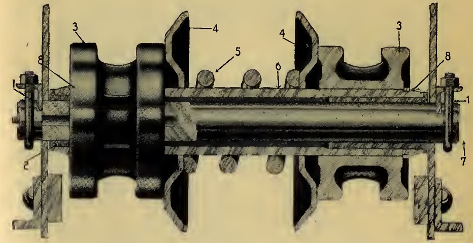
One of the lower road-track rollers with spring plates is crossed here. The inner face of the tracks featured rails which meshed with the channels in the rollers. The rollers without the springs were similar except for the springs' and spring plates' absence. 1. U bolt. 2. Floating bushings. 3. Roller. 4. Spring plate. 5. Spring. 6. Tube. 7. Roller pin. 8. Spring ring. (Picture from Preliminary Handbook of the Mark VIII Tank.)
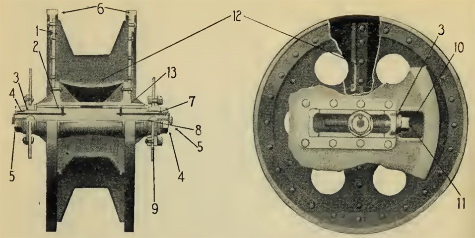
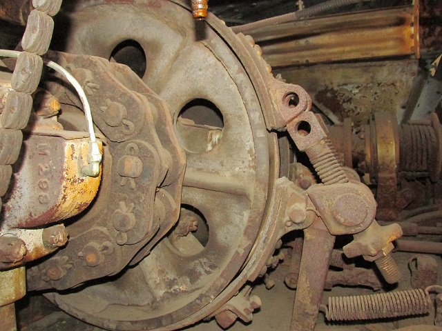
The idler wheel, referred to as the road-track adjusting wheel, could be used to adjust track tension via the adjusting screw found on each side of each wheel. To change the tension, the locking screws needed to be loosened, then the tension-adjusting screws could be used to move the wheel to the front or rear. 1. Disc for road-track adjusting wheel. 2. Bush for road-track adjusting wheel. 3. Bracket for tension-adjusting screw. 4. Nut for shaft for track-adjusting wheel. 5. Locking screw for adjusting wheel. 6. Rim for road track. 7. Bracket for tension-adjusting screw. 8. Shaft for tension-adjusting screw. 9. Plate for track-adjusting bracket. 10. Guard in hull plate for adjusting screw. 11. Tension-adjusting screw. 12. Diaphragm road-track adjusting wheel. 13. Boss for road-track adjusting wheel. (Picture from Preliminary Handbook of the Mark VIII Tank.)
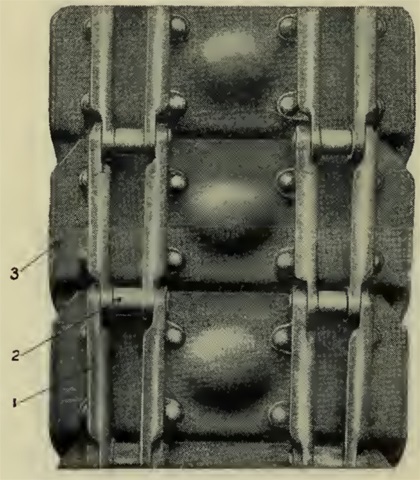
The inner faces of three track shoes can be seen here. The links were drop forged steel, and as the tank progressed the links formed a rail bed over which the road-track rollers could roll. Left and right link bars were joined by pins surrounded by carbon-steel bushings. The links were riveted to the track shoes. 1. Road-track link. 2. Bushing for road-track link. 3. Road-track shoe. (Picture from Preliminary Handbook of the Mark VIII Tank.)
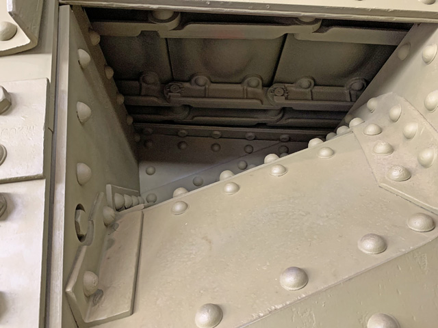
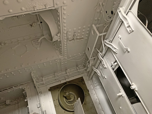
The tracks were visible when looking up through the mud chutes, as demonstrated here when peering into the rear chute.
The starboard sponson is shown here rolled back for shipping. (Picture from Preliminary Handbook of the Mark VIII Tank.)
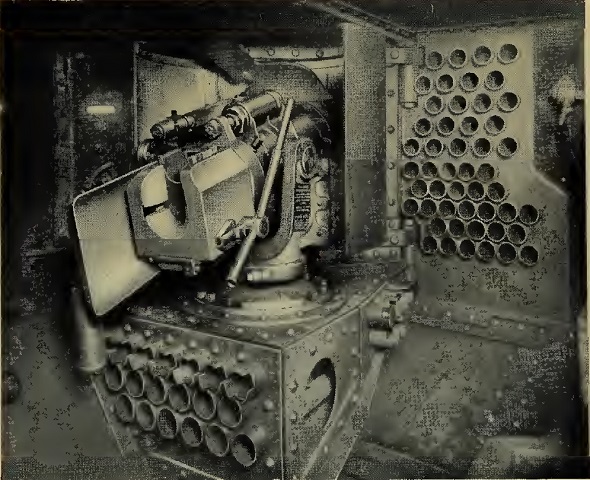
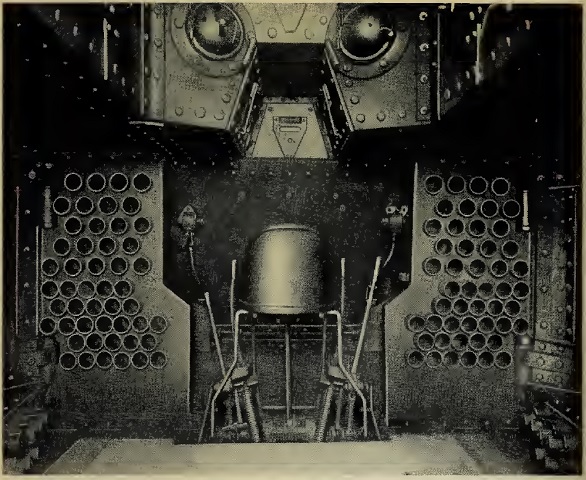
The port 6 pounder is shown here mounted in the sponson and facing forward. The large ammunition rack is the one to the driver's left, and the spark lever can be seen on the inner hull wall. Thirteen smoke shells could be accommodated in the top rows of the magazine under each of the 6 pounders in special cylindrical cases; the rest of the stowage was for common shells: 49 on each side of the driver, 60 in the center stowage of the hull, and 12 in each sponson magazine. (Picture from Preliminary Handbook of the Mark VIII Tank.)
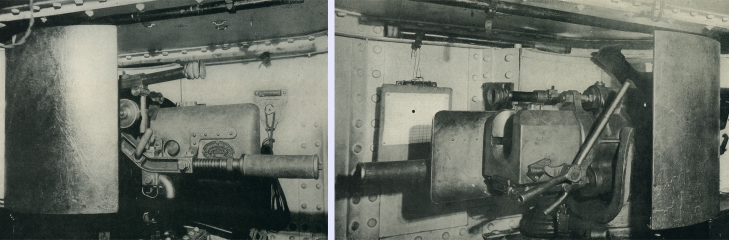
A 6 pounder mount is shown from the left and right. On the left side, the trigger grip is visible along with the telescope, which had 2x magnification and a 20° field of vision. Open sights were fitted to the telescope holders, with an acorn to the front and a V at the rear. The cylinder pointing to the rear of the mount behind the trigger grip is the gunner's shoulder piece, which was a rubber-padded steel bar held in place by a sleeve tensioned by a spiral spring. The sleeve could be retracted and the shoulder piece hinged downward when not in use. The crank handle on the right side of the gun was used to open the breech for loading, and after the shell was pushed home until the case rim engaged the hook on the extractor, the crank handle was pushed forward to close the breech. (Picture from Handbook for the Q. F. Hotchkiss 2.244-inch, 6-pdr., 6-cwt, Mark II Gun with Tank Mounting.)

Cross-sections of the 6 pounder mount are provided here. The recoil cylinder had five tapered grooves to accommodate the flow of oil from one side of the recoil piston to the other. During recoil, the piston was moved rearward as it was attached to a rod connected to the recoil band of the gun. The resistance of the oil as it flowed through the grooves of the cylinder as the piston was pulled to the rear absorbed the recoil energy. The two counter-recoil springs were also compressed during recoil, absorbing more energy and then expanding to return the gun to battery. A projection on the recoil piston entered a recess in the closing plug of the recoil cylinder as it finished its counter-recoil stroke, displacing oil in the recess and cushioning the shock of the counter-recoil action. A. Pivot plate. B. Clip ring. C. Revolving bracket. D. Trunnion bearing caps. E. Pivot bolt. F. Cradle. G. Hydraulic recoil cylinder. H. Stuffing box. I. Gland. J. Packing. K. Closing plug. L. Filling plug. M. Piston rod and piston. N. Counter recoil cylinders. O. Counter recoil springs. P. Counter recoil rod. Q. Front steel head. R. Rear-end plate. S. Steel plug. T. Clamp. (Picture from Handbook for the Q. F. Hotchkiss 2.244-inch, 6-pdr., 6-cwt, Mark II Gun with Tank Mounting.)
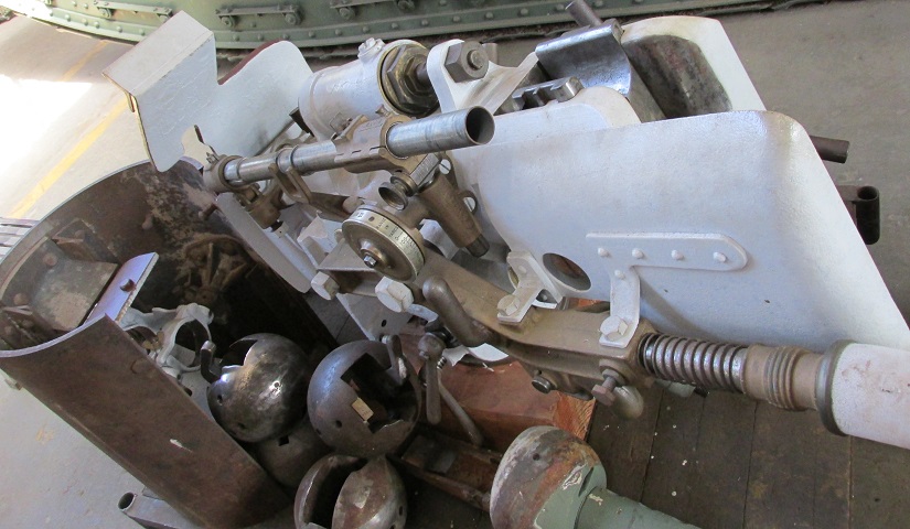
The 6 pounder has been removed from the left-hand sponson and can be seen here. A green machine gun shroud is below the 6 pounder, and round machine gun mounts are piled up to the lower left. The 6 pounder's vertically-sliding breechblock can be seen behind the recoil shield, and the sighting telescope holder, range dial, and trigger grip can be seen on the gold-colored frame on the left side of the mount. Together, the gun and breech weigh 644lb (292kg), and the ordnance is 23 calibers long including the chamber.
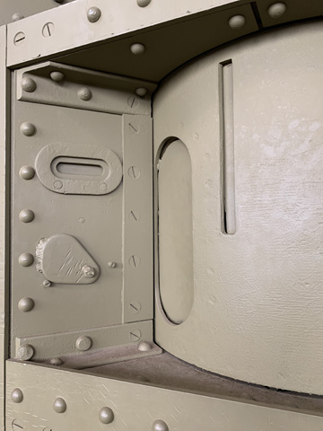
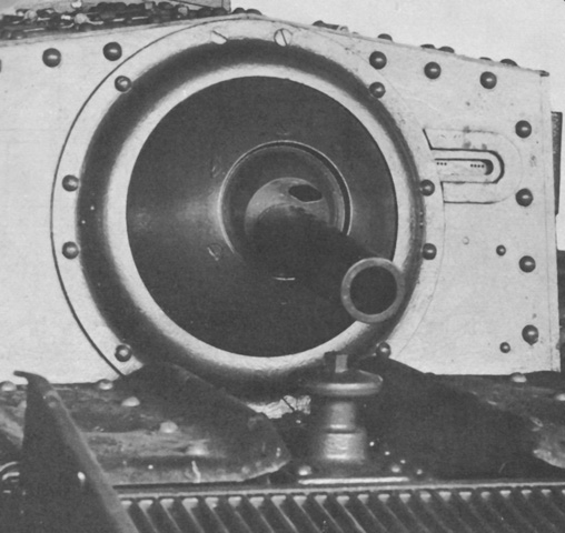
The left-side 6 pounder rotor is shown without the ordnance mounted. The aperture for the gun and the telescopic sight both have patches installed, and a pistol port and vision slit are forward of the gun mount.
The machine guns were mounted in 9" (23cm) ball mounts. A large direct vision port can be seen in the ball above the gun's barrel protector tube; this port could be closed with a plug when not in use. The ball mounts in the side doors and turret rear, seen in this image, were further installed in large bell housings. (Picture from Weapon Mounts for Secondary Armament.)
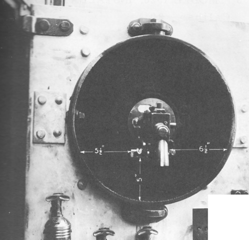
The right-side door machine gun ball mount is seen from the inside. The bell housings were provided with trunnions on the top and bottom in order to add more horizontal traverse. (Picture from Weapon Mounts for Secondary Armament.)
External and internal views of the machine gun mount in the left hull door are shown here.
The machine gun ball mounts on either side of the turret front were not ensconced in bell housings. (Picture from Weapon Mounts for Secondary Armament.)
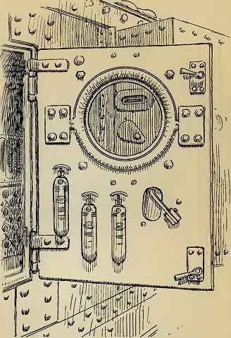
Three Pyrene fire extinguishers were mounted on each door, and two more were found in the engine room, for a total of eight extinguishers in the tank. The extinguishers are sketched here mounted inboard of the revolver hole on the right-side door. (Picture from Preliminary Handbook of the Mark VIII Tank.)
