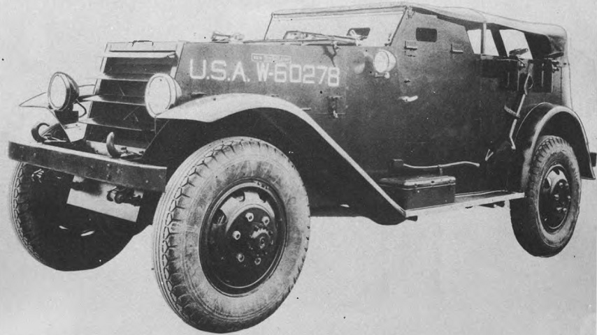
Scout Car M2.
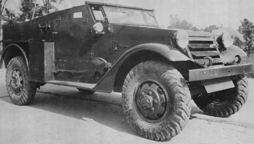
The scout car M2 featured external pintle mounts for its .30cal machine guns, and two of these can be seen above the rear wheel. This car has its removable canvas top installed, and the protective flaps have been lowered in front of the drivers and raised on the side door. This machine happens to be the prototype of the M2, the scout car T9, and was made from mild steel. (Picture from Development of Armored Vehicles, volume II: Armored Cars, Scout Cars, and Personnel Carriers.)
With the canvas top removed, the interior seating can be seen from this steep angle. A .30cal machine gun is mounted in a pintle on the far side of the car, and a radio antenna has been attached to the exterior behind the driver. The armored windshield is raised, and the armored door flaps have been lowered. (Picture taken 1 Jul 1938 by E.O. Goldbeck; available from the Library of Congress.)
Stowage on the other side can be seen here, including a pick and a canvas bucket. No machine guns are present, but a radio antenna is visible behind the driver. (Picture taken 1 Jul 1938 by E.O. Goldbeck; available from the Library of Congress.)
In contrast to the earlier M2 on the right, the scout car M2A1 (later renamed M3) on the left had a skate rail mounted even with the top of the armor. The layout of the side armor was changed from the earlier machine to protect the rail, and stowage racks took advantage of the larger amount of surface area. (Picture taken 1 Jul 1938 by E.O. Goldbeck; available from the Library of Congress.)
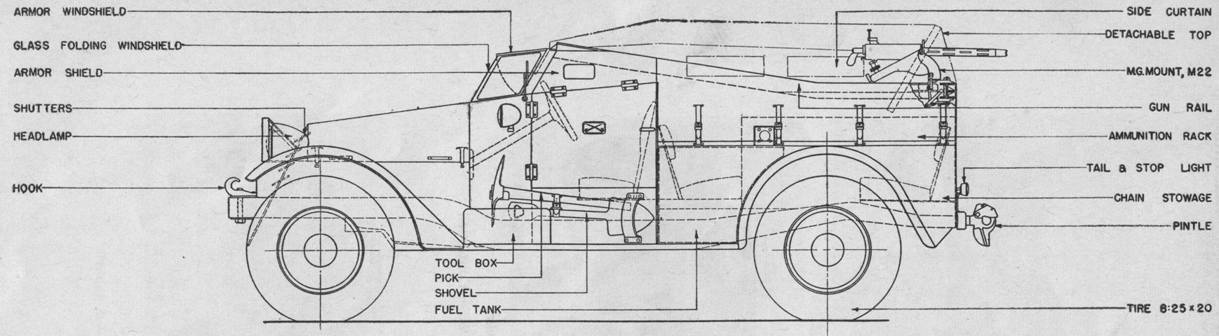
The .25" (.64cm) shatterproof glass windshield featured side wing panes and protruded to the edge of the armored flap above. The glass windshield folded forward and secured to the hood when the armored flap was lowered. (Picture from Tank Data, volume 3.)
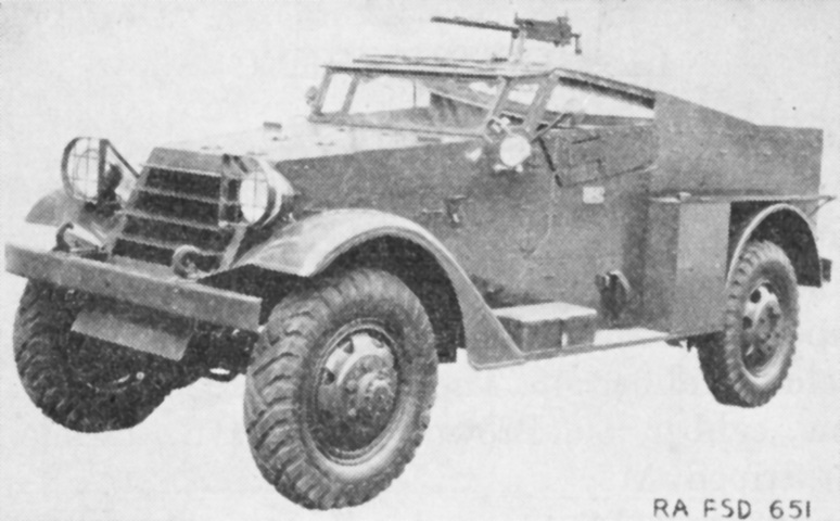
Brush guards now protect the Guide Lamp Corp. Model 828-M 8.25"- (21.0cm-) lens headlights, and a .30cal machine gun is present. (Picture from TM 9-705 Scout Cars, M3, M3A1, and 4.2 Mortar Motor Carriage, M2.)
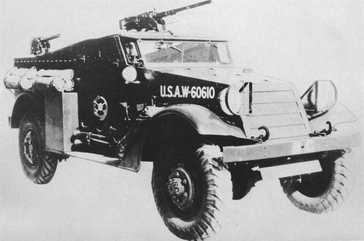
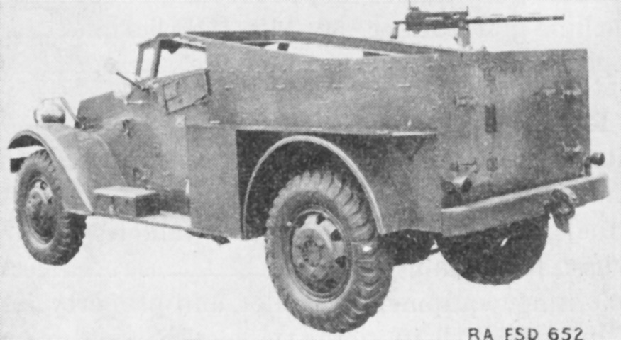
A .50cal machine gun in mounted on this vehicle in addition to the .30cal. (Picture from Development of Armored Vehicles, volume II: Armored Cars, Scout Cars, and Personnel Carriers.)
The rear door and the path of the machine gun rail in the passenger compartment can be seen from behind. (Picture from TM 9-705 Scout Cars, M3, M3A1, and 4.2 Mortar Motor Carriage, M2.)
The opposite angle is shown in this picture. (Picture from TM 9-705 Scout Cars, M3, M3A1, and 4.2 Mortar Motor Carriage, M2.)
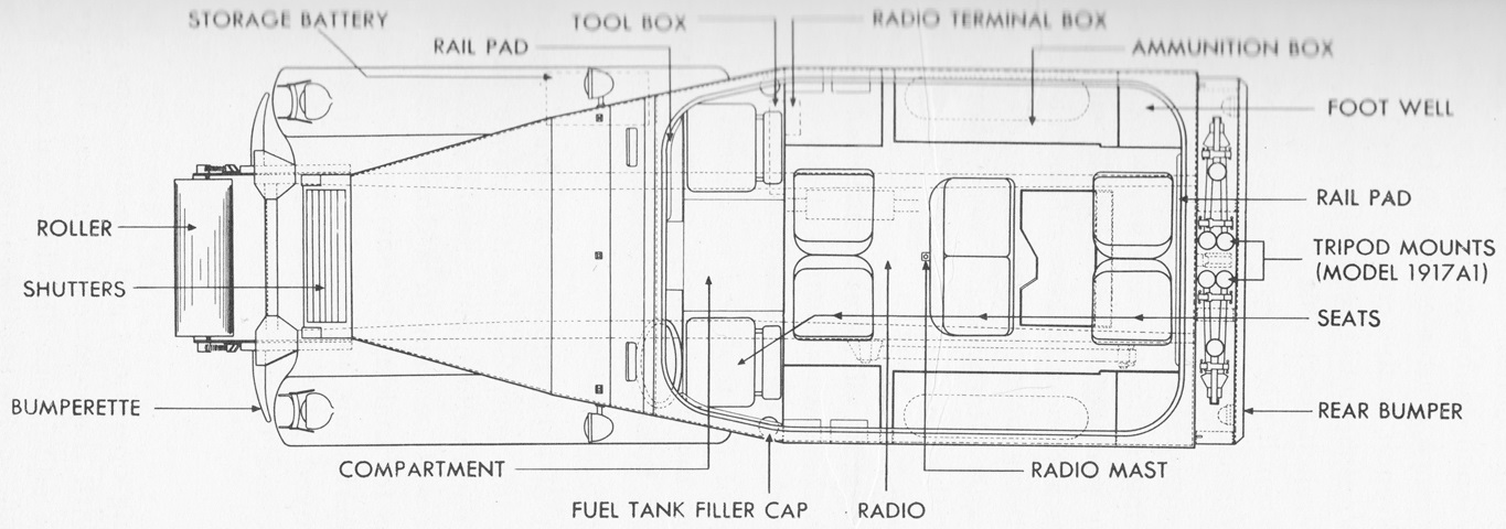
The machine gun skate rail is visible in this overhead view. (Picture from FM 30-40 Military Intelligence Identification of United States Armored Vehicles.)
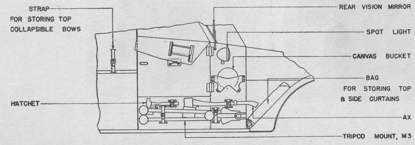
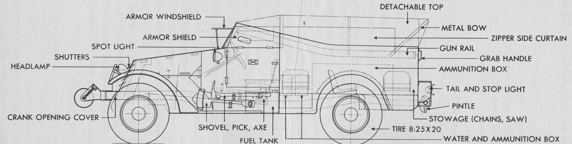
External stowage and some internal features are labeled here. Note the seating arrangement in the rear. (Picture from TM 9-705 Scout Cars, M3, M3A1, and 4.2 Mortar Motor Carriage, M2.)
Stowage on the front right side of the vehicle is diagrammed in this sketch. The tripod mount M3 was for the .50cal M2HB machine gun. (Picture from TM 9-705 Scout Cars, M3, M3A1, and 4.2 Mortar Motor Carriage, M2.)
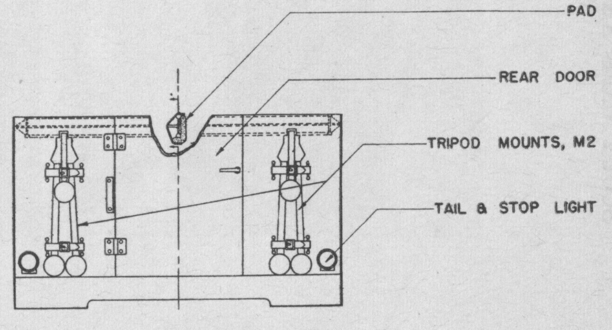
The tripod mounts M2 stowed on the hull rear were for the .30cal M1917A1 machine guns. (Picture from TM 9-705 Scout Cars, M3, M3A1, and 4.2 Mortar Motor Carriage, M2.)
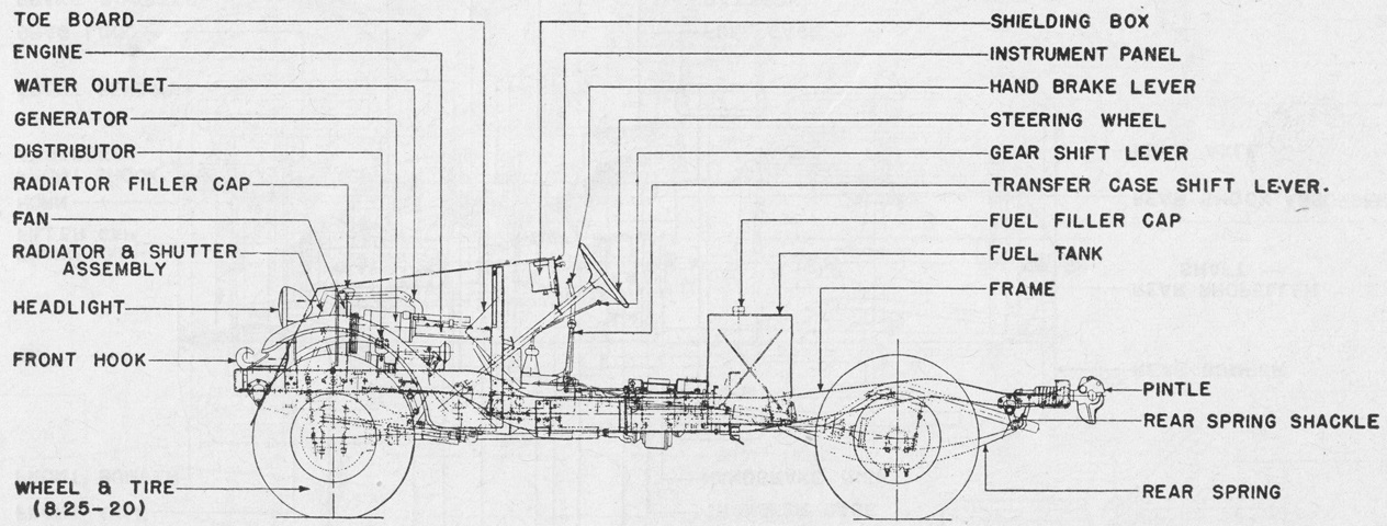
The chassis is diagrammed here in plan view. (Picture from TM 9-705 Scout Cars, M3, M3A1, and 4.2 Mortar Motor Carriage, M2.)
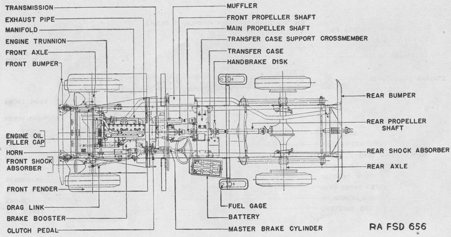
Further details of the chassis are sketched here. The Hotchkiss drive principle was used at the rear springs. (Picture from TM 9-705 Scout Cars, M3, M3A1, and 4.2 Mortar Motor Carriage, M2.)
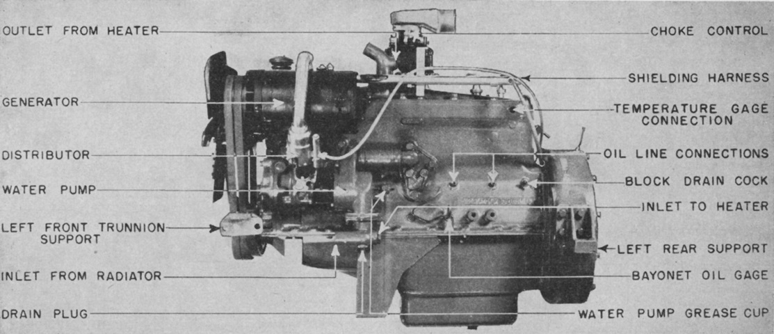
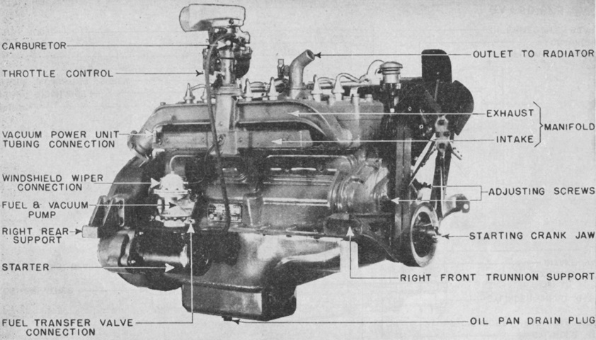
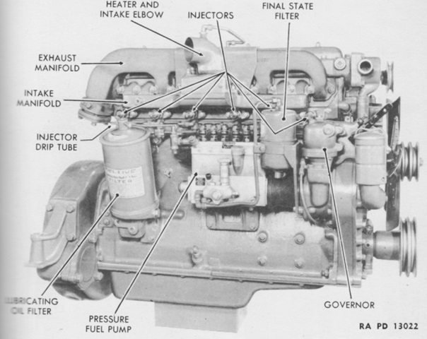
The left side of the engine is labeled in this picture. Bore and stroke were 4" and 4.25" (10cm and 10.8cm), respectively, for a displacement of 320in³ (5,240cm³). (Picture from TM 9-705 Scout Cars, M3, M3A1, and 4.2 Mortar Motor Carriage, M2.)
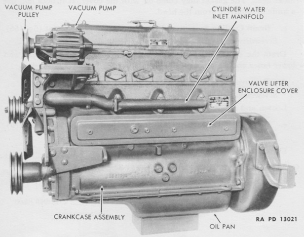
The engine's right side is displayed here. Weight including the flywheel, timing drive, and oil and water pumps was 590lb (270kg) without accessories. (Picture from TM 9-705 Scout Cars, M3, M3A1, and 4.2 Mortar Motor Carriage, M2.)
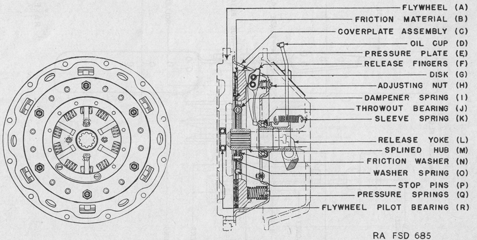
The Long Manufacturing Co. Model 12-CB-CL clutch was a single-plate, dry disk, semicentrifugal unit with a mechanical spring-and-friction vibration dampener and automatic adjustment to compensate for wear. It could be interchanged with the Rockford (Borg-Warner) Model CLA-1191 found on the scout car M3A1. (Picture from TM 9-705 Scout Cars, M3, M3A1, and 4.2 Mortar Motor Carriage, M2.)
The transmission is shown from the left and right. It used the SAE standard 4-speed truck gear shift. The ratio for first gear was 5.00:1, second was 3.07:1, third was 1.71:1, fourth was 1.00:1, and reverse was 5.83:1. (Picture from TM 9-705 Scout Cars, M3, M3A1, and 4.2 Mortar Motor Carriage, M2.)
The Wisconsin Axle Co. Model T-32-9 transfer case provided an additional speed reduction for prolonged slow-speed driving or developing maximum traction, and it also offset the front propeller shaft so that it didn't foul the engine's crankcase. Pushing the transfer case shift lever forward enabled the usual direct drive, and pulling the lever to the rear changed to the low ratio of 1.94:1. (Picture from TM 9-705 Scout Cars, M3, M3A1, and 4.2 Mortar Motor Carriage, M2.)
The third lever emanating from the transmission was for operating the American Cable Tru-Stop hand brake that arrested the propeller shaft to the rear of the transfer case. Two brake shoes clamped a disc mounted on a companion flange of the propeller shaft. (Picture from TM 9-705 Scout Cars, M3, M3A1, and 4.2 Mortar Motor Carriage, M2.)
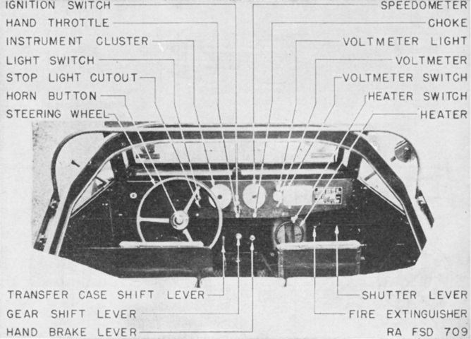
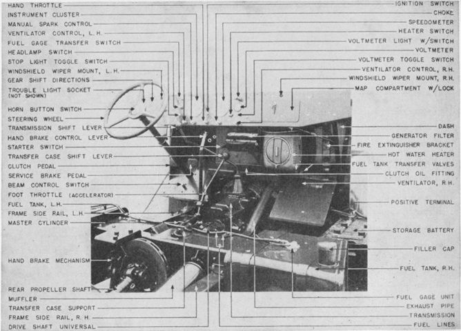
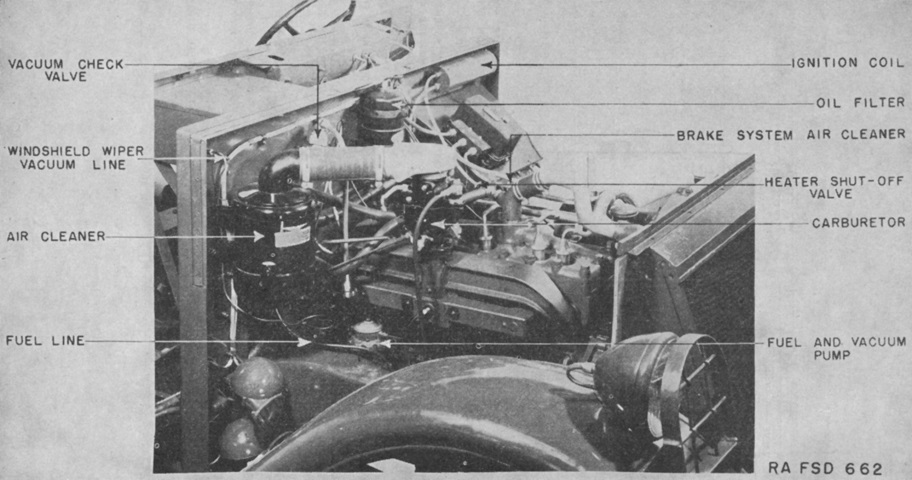
The instruments and controls are labeled in this image. The shutter lever controlled the radiator shutters. A portable 1-quart (1L) Pyrene fire extinguisher was mounted in the driver's compartment. (Picture from TM 9-705 Scout Cars, M3, M3A1, and 4.2 Mortar Motor Carriage, M2.)
Details of the carriage mount M21 for the .50cal machine gun are shown here. (Picture from TM 9-705 Scout Cars, M3, M3A1, and 4.2 Mortar Motor Carriage, M2.)
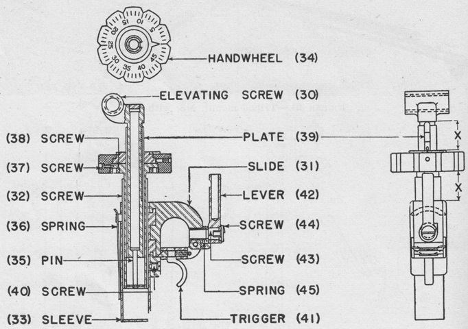
The carriage mount elevation mechanism functioned similarly to that found on the tripod mount. The elevating handwheel (34) was graduated into fifty 1-mil divisions, and a click mechanism provided the gunner with feedback when going through each division. (Picture from TM 9-705 Scout Cars, M3, M3A1, and 4.2 Mortar Motor Carriage, M2.)
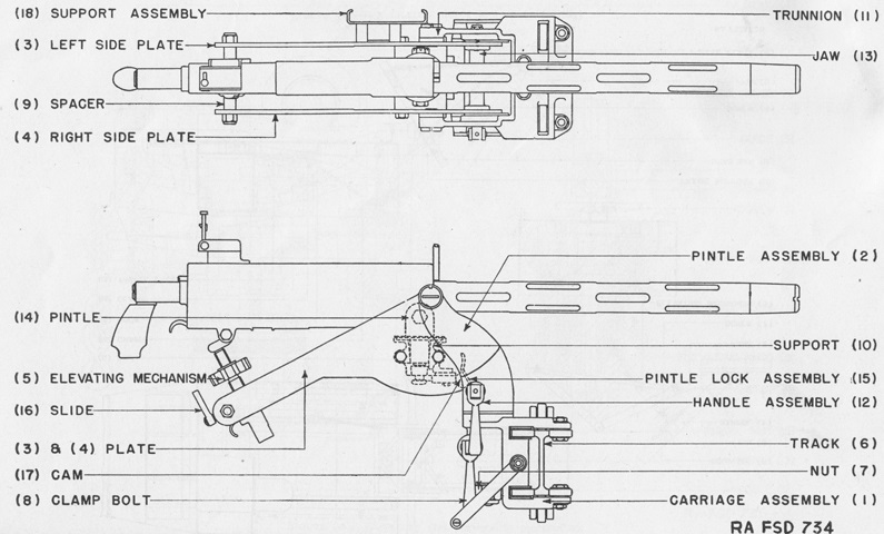
The .30cal machine gun's carriage mount M22 can be compared to the mount for the .50cal machine gun. (Picture from TM 9-705 Scout Cars, M3, M3A1, and 4.2 Mortar Motor Carriage, M2.)
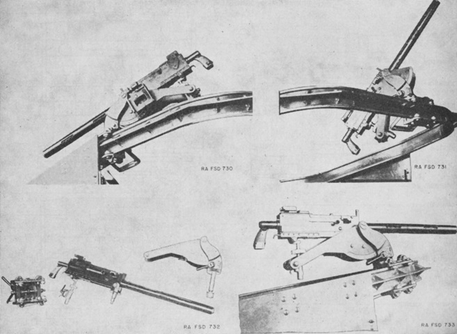
The carriage mount M22 is shown disassembled on the lower left, and mounted on the track in the other images. (Picture from TM 9-705 Scout Cars, M3, M3A1, and 4.2 Mortar Motor Carriage, M2.)
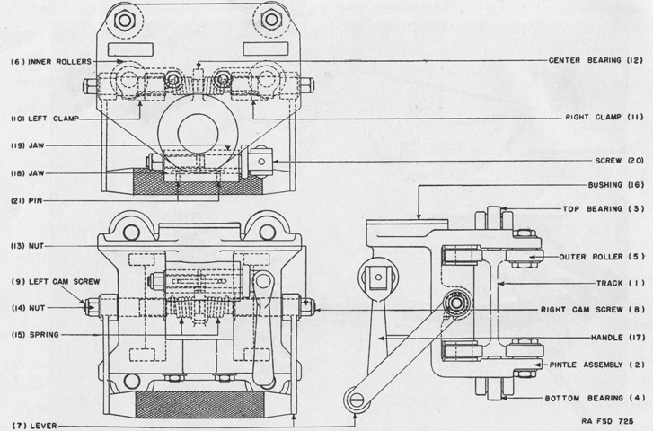
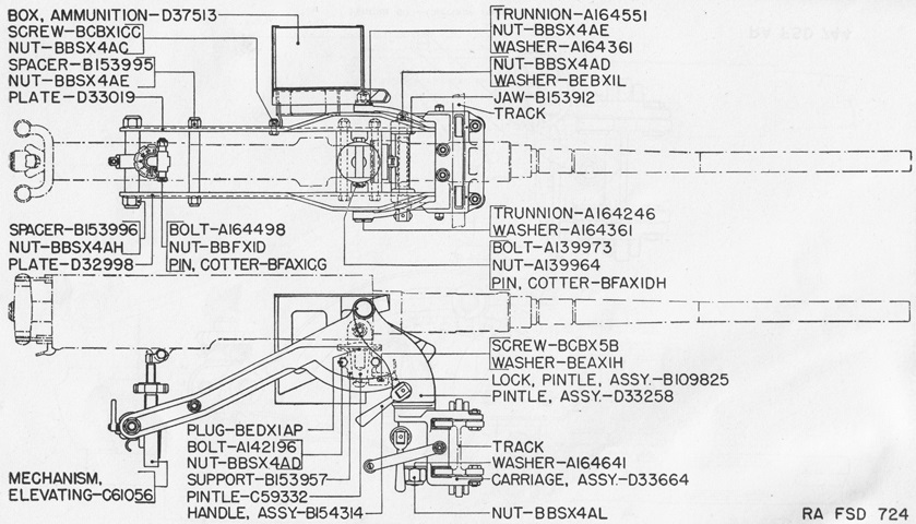
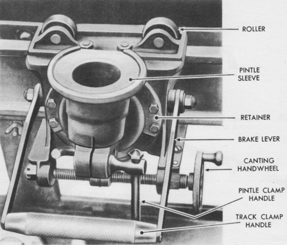
The rolling carriage for both machine gun mounts is diagrammed in this picture. The carriage rode on the track via the two top (3) and two bottom (4) bearings and four inner (6) and four outer (5) rollers. It could be locked to the track by lever (7); the lever was raised to unlock the carriage. Handle (17) clamped the machine gun pintle into bushing (16) by closing jaws (18) and (19). (Picture from TM 9-705 Scout Cars, M3, M3A1, and 4.2 Mortar Motor Carriage, M2.)
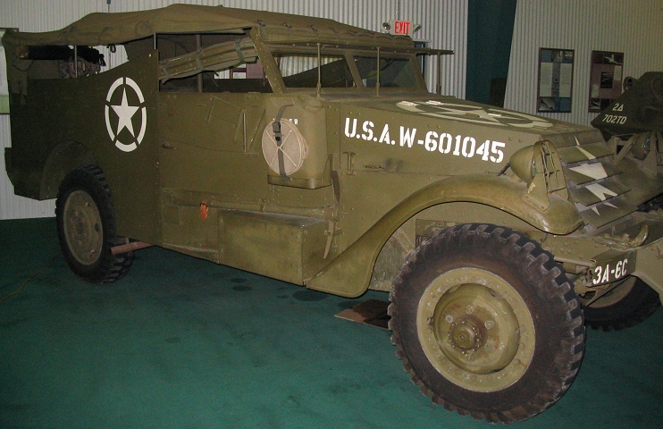
Compared to the cars above, the wider body of the M3A1 is obvious. The top-hinged armored windshield cover is raised on this vehicle, and the glass panels can be contrasted to the earlier vehicle above. The box on the passenger running board housed the battery. The armored radiator louvres at the front of the vehicle were controlled in the driver's compartment, and the engine exhaust pipe can be see in front of the rear wheel. The headlights have decreased in size, being Guide Lamp Corp. Model 364-E units with a 6.24" (15.9cm) lens. (Picture from TM 9-705 Scout Car M3A1.)
The armored flap on the driver's door is lowered; it folded outward. (Picture from TM 9-705 Scout Car M3A1.)
The rear door found on earlier scout cars was eliminated on the M3A1. (Picture from TM 9-705 Scout Car M3A1.)
External stowage and internal details are revealed in this sketch. Note the revised seating arrangements in the passenger compartment as well as the relocated fuel tank. (Picture from TM 9-705 Scout Car M3A1.)
The rearranged seating is easier to see in this top-down view. (Picture from TM 9-705 Scout Car M3A1.)
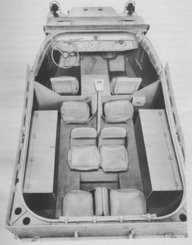
The seating arrangements and internal stowage can be seen in this picture. (Picture from TM 9-705 Scout Car M3A1.)
The canvas top is on this car, but rolled up at the sides and rear. The machine gun skate rail can be seen above the passenger door; note the padding to protect passengers.
This vehicle has its canvas top removed since it's a pleasant day. A .50cal M2HB machine gun is facing forward over the hood, and a .30cal M1917A1 machine gun faces out from each side of the passenger compartment.
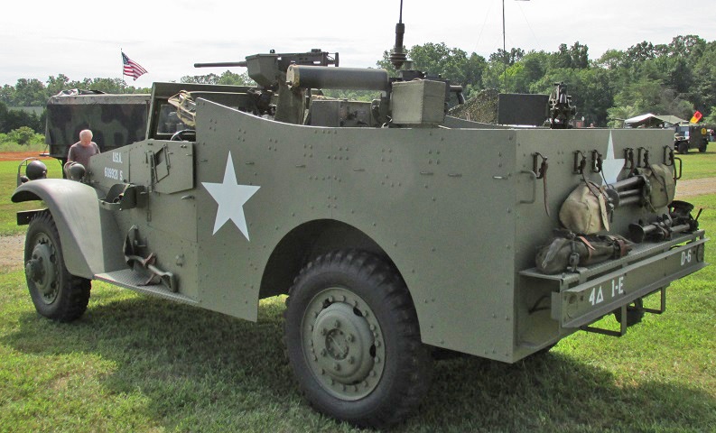
This rear view showcases the water-cooled .30cal machine guns. Stowage for the machine gun tripods is visible on the rear plate and bumper.
A view into the passenger compartment from the driver's door is shown here. The tall radio installation can be seen behind the driver's seat, and details of the .30cal MG skate mount are visible towards the rear of the vehicle. The rail was lower when compared with the scout car M3, where the rail was even with the top of the armor.
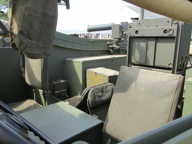
The driver's and front passenger's seats are shown here. The bottom of the cradle mount for the .50cal MG can be seen at the top of the image.
The controls and instruments from an early-production car are labeled in this image. (Picture from TM 9-705 Scout Cars, M3, M3A1, and 4.2 Mortar Motor Carriage, M2.)
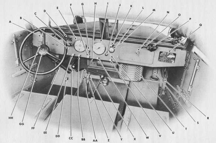
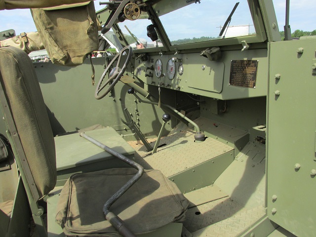
A later-production driver's compartment is detailed here. A 2lb (.9kg) portable CO2 fire extinguisher was normally secured in the driver's compartment. A. Trouble light receptacle. B. Stop light switch. C. Blackout and service lights switch. D. Dual fuel tank selector switch for fuel gage. E. Instrument cluster [clockwise from top: ammeter, oil pressure gage, water temperature gage, fuel gage]. F. Throttle control. G. Ignition switch. H. Starter motor switch. I. Speedometer. J. Heater switch. K. Dash light. L. Voltmeter. M. Screw. N. Map compartment door with key. O. Windshield wiper tube. P. Windshield wiper assembly. Q. Vehicle registration plate. R. Radiator shutter control lever. S. Fire extinguisher bracket. T. Heater. U. Voltmeter push switch. V. R. H. ventilator control. W. Choke. X. Transfer case shift lever. Y. Hand brake lever. Z. Transmission gearshift lever. AA. Accelerator pedal. BB. Spark. CC. Brake pedal. DD. Foot dimmer switch. EE. L. H. ventilator control. FF. Clutch pedal. GG. Horn button. HH. Gearshift instruction plate. (Picture from TM 9-705 Scout Car M3A1.)
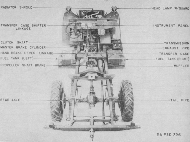
A plan view of the chassis is labeled here. (Picture from TM 9-705 Scout Cars, M3, M3A1, and 4.2 Mortar Motor Carriage, M2.)
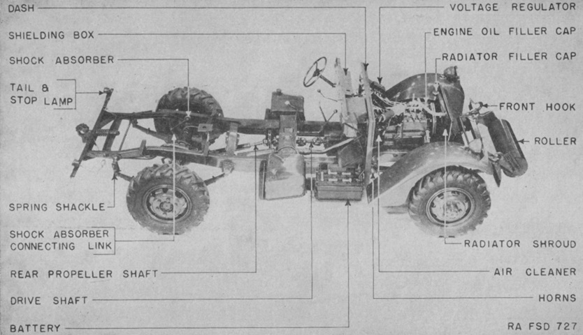
The chassis is shown in elevation. (Picture from TM 9-705 Scout Cars, M3, M3A1, and 4.2 Mortar Motor Carriage, M2.)
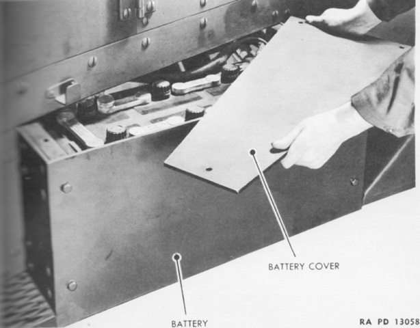
The 12-volt, 6-cell, 25-plate lead-acid battery was moved from its left-side position on the scout car M3 to a box below the right door. (Picture from TM 9-705 Scout Car M3A1.)
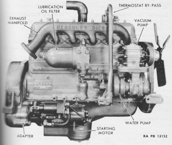
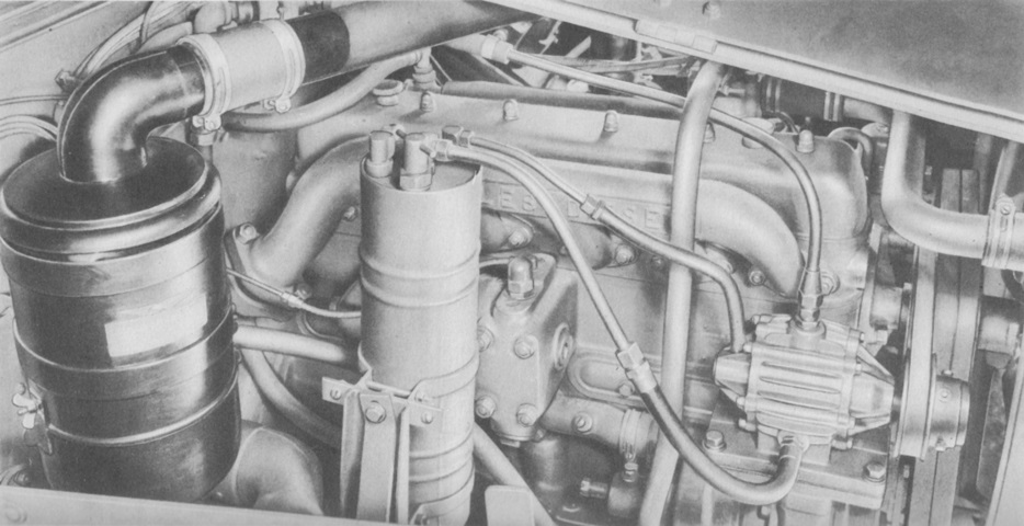
The Hercules JXD engine is installed in this picture. (Picture from TM 9-705 Scout Cars, M3, M3A1, and 4.2 Mortar Motor Carriage, M2.)
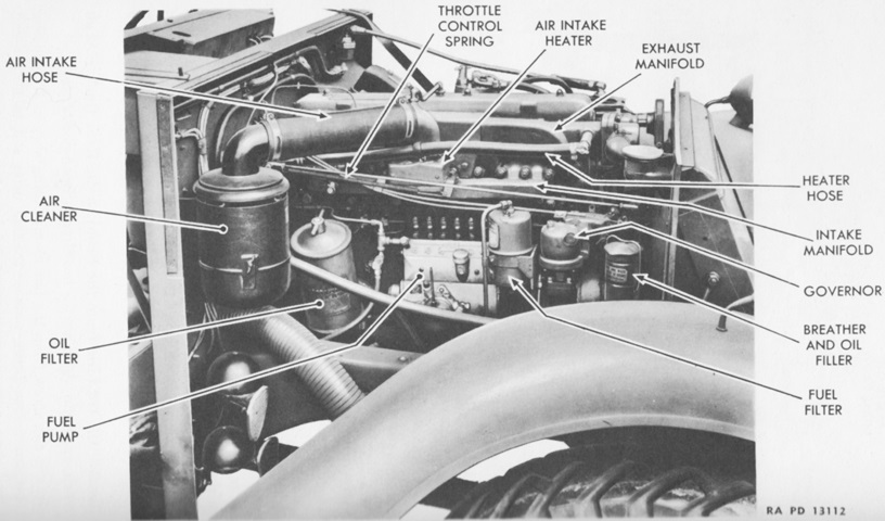
The right side of the Hercules DJXD diesel engine is shown here. Bore and stroke were 4" and 4.5" (10cm and 11.4cm), respectively, for a displacement of 339in³ (5,560cm³). (Picture from TM 9-705 Scout Car M3A1.)
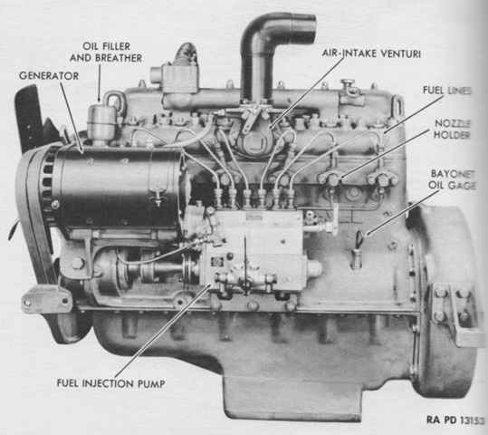
The DJXD's compression ratio was 14.5:1, and with accessories it weighed 3,380lb (1,530kg). (Picture from TM 9-705 Scout Car M3A1.)
The DJXD is shown here installed in the engine compartment. (Picture from TM 9-705 Scout Car M3A1.)
Parts of the right side of the 6DT-317 are labeled here. (Picture from TM 9-705 Scout Car M3A1.)
The Buda-Lanova 6DT-317 had a bore and stroke of 3.625" and 5.125" (9.208cm and 13.02cm), respectively, for a displacement of 317in³ (5,190cm³). (Picture from TM 9-705 Scout Car M3A1.)
The 6DT-317 is shown installed in this picture. (Picture from TM 9-705 Scout Car M3A1.)
The transmission is installed in this picture. First and second speeds were sliding mesh, while third and fourth were constant mesh. (Picture from TM 9-705 Scout Car M3A1.)
The Wisconsin Axle Co. Model T-32-15 transfer case was behind the transmission on rubber mounts. (Picture from TM 9-705 Scout Car M3A1.)
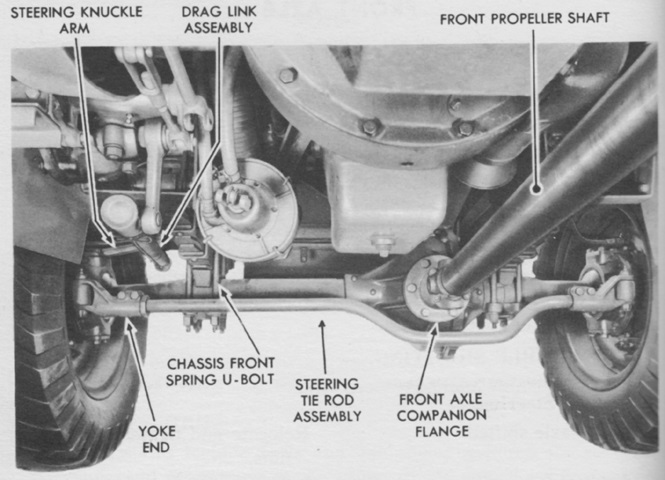
The front axle was a spiral-bevel, single-reduction, full-floating type with a straddle-mounted pinion gear and a standard type differential. Rzeppa-type universal joints enclosed in knuckles at the axle ends drove the front wheels. (Picture from TM 9-705 Scout Car M3A1.)
Two types of springs were used to suspend the front axle. The early type featured a joint between the center and outer sections of the third leaf, which then resembled a broken leaf. The later spring had the top three leaves wrap around the shackle pin bushing, and the top leaf's center section was articulated with two intersections. (Picture from TM 9-705 Scout Car M3A1.)
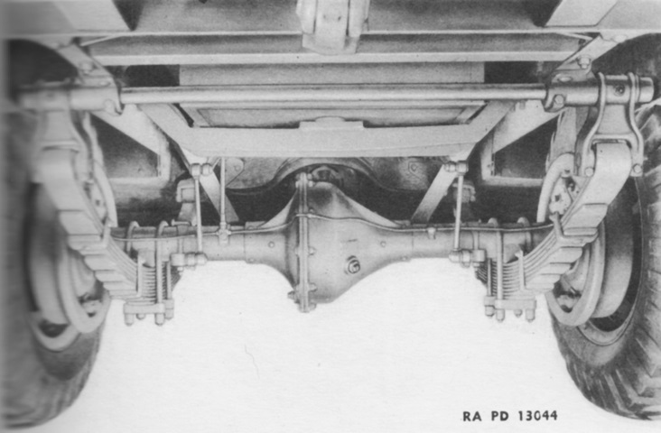
The rear axle was also a single-reduction, full-floating type with a straddle-mounted pinion gear and a standard type differential. It featured a split housing, and the drive pinion and differential assemblies were the same as those in the front axle. (Picture from TM 9-705 Scout Car M3A1.)
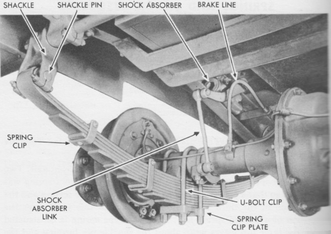
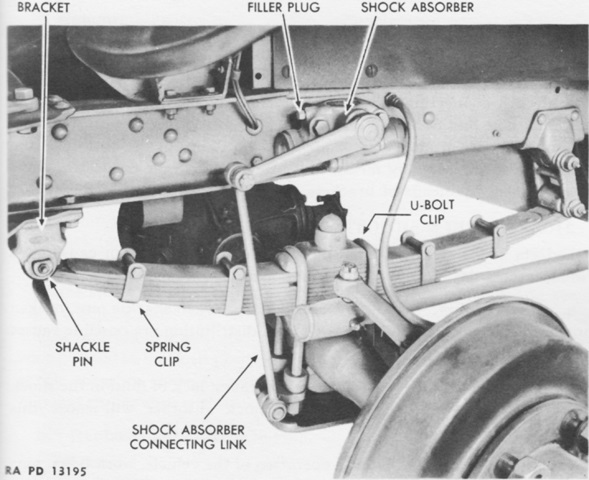
Components of the rear suspension are labeled in this picture. (Picture from TM 9-705 Scout Car M3A1.)
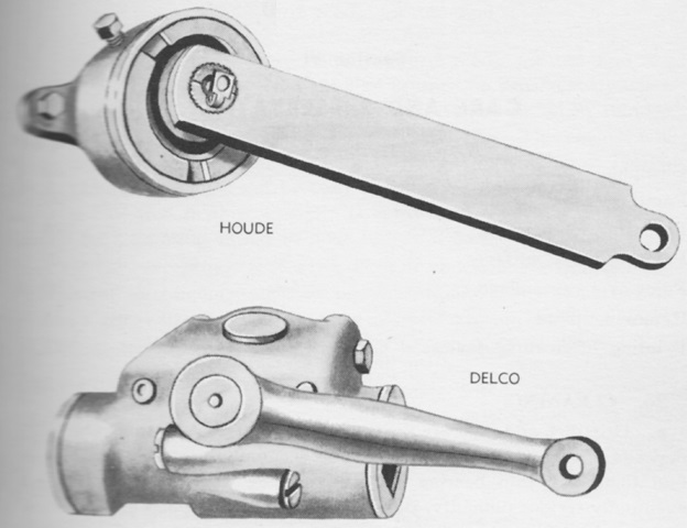
Two types of double-acting shock absorbers were used, made by either Houde or Delco. The shock absorber mechanism was bolted to the car's frame above the relevant spring. The Houde type used heavy shock absorber fluid, while the Delco used light shock absorber fluid. (Picture from TM 9-705 Scout Car M3A1.)
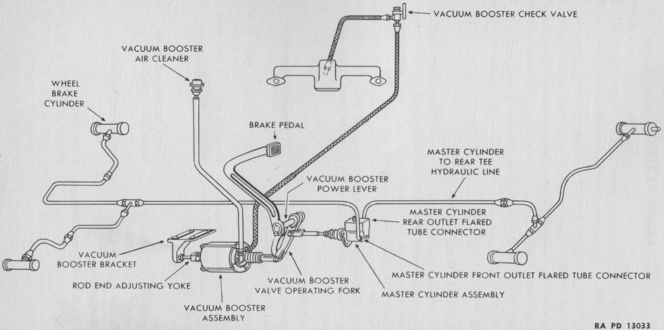
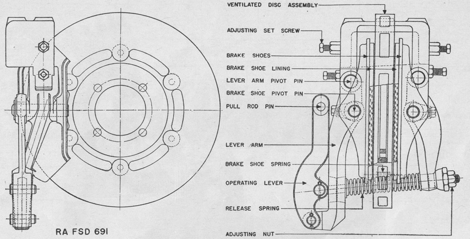
A schematic of the hydraulic brake system is sketched here. (Picture from TM 9-705 Scout Car M3A1.)
This image shows the machine gun mount carriage M30. The carriage could be locked at any point on the rail and canted to compensate for the vehicle's position. An anticant device also accounted for the track's horizontal displacement. (Picture from TM 9-705 Scout Car M3A1.)
 Scout Car M3A1.
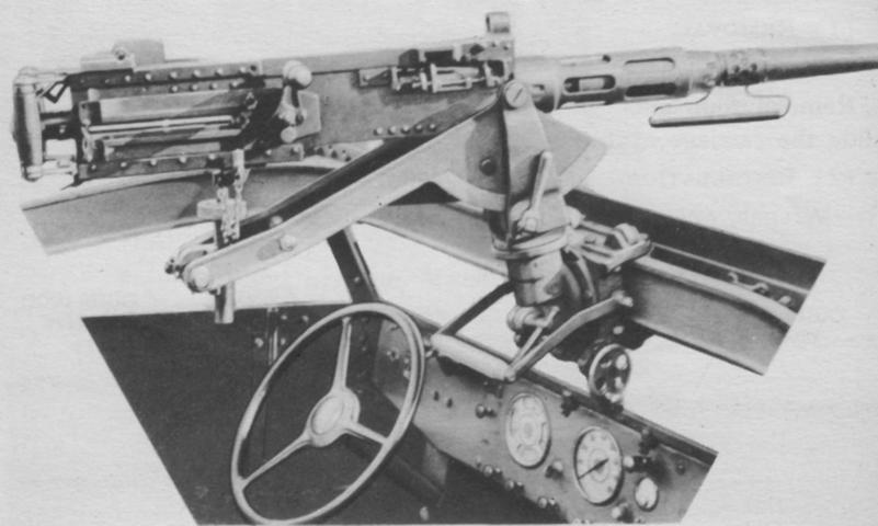
The cradle mount M30 for the .50cal machine gun is pictured here. The gun was restricted to traverse of 160° (80° left or right) in the mount, but the rail allowed 360° coverage. The M35 skate mount differed from the M30 by using a T-shaped support for the rear of the gun instead of the more complex support used in the M30, which allowed fine adjustments in elevation and traverse. The M35C supported the machine gun directly with the cradle, and only shared the pintle socket and carriage assembly with the M35. Traverse and elevation were the same for them all. (Picture from TM 9-705 Scout Car M3A1.)
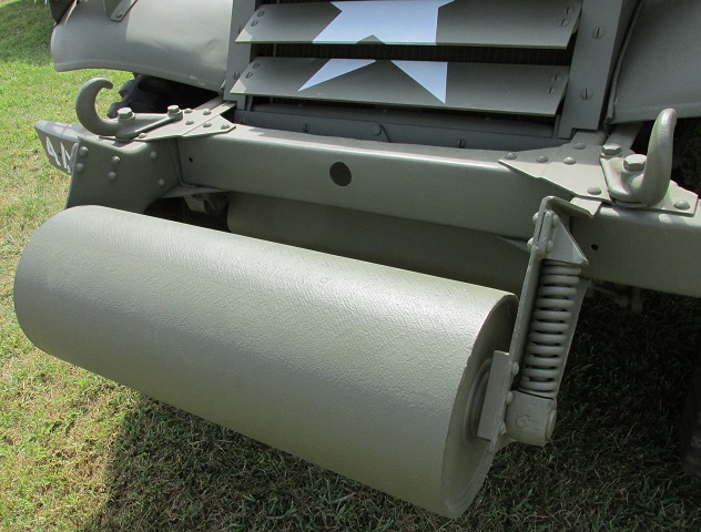
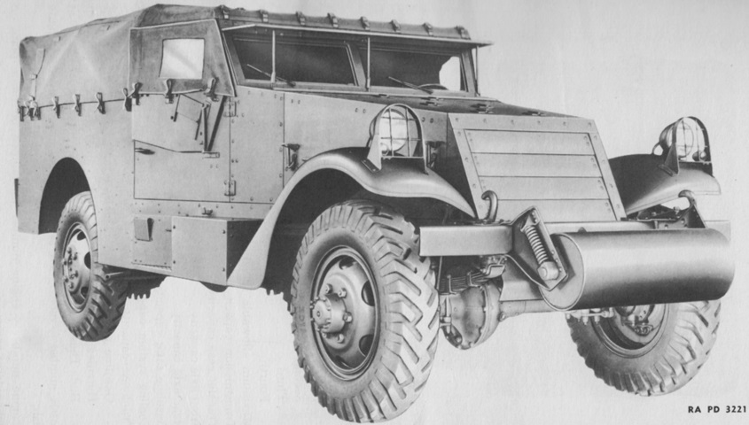
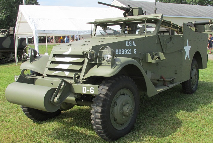
Details of the anti-ditching roller can be seen here.
