Medium Armored Car T17E1 Staghound I.
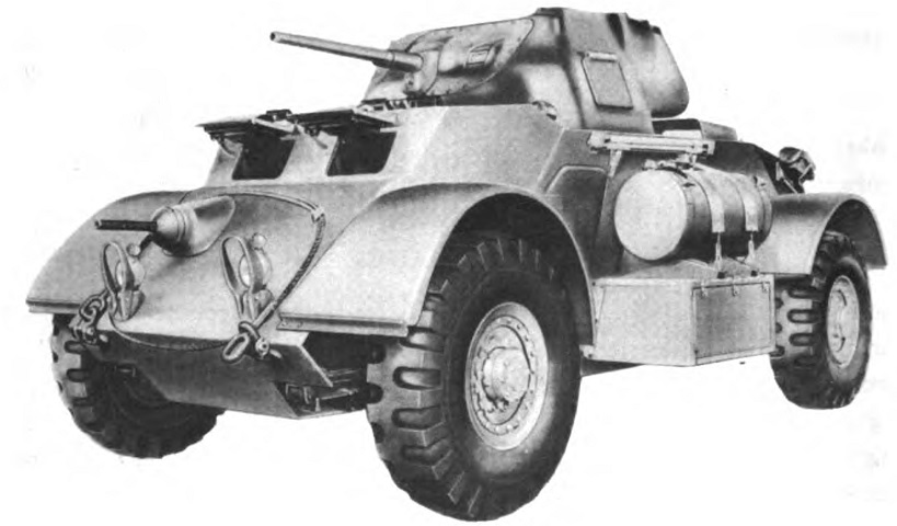
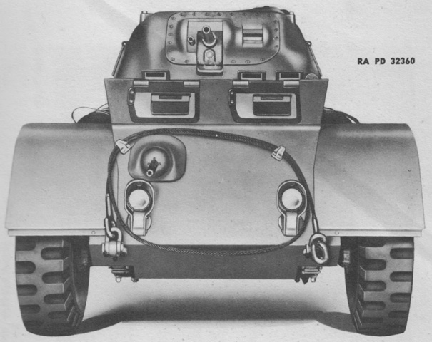
One of the jettison fuel tanks on the T17E1 can be seen strapped down above the luggage box between the wheels. The release lever was above the side door, and an automatic valve closed the gas line from the tank once it was released. The drivers' front vision doors are open on this vehicle, and blackout marker lamps are attached above the head lamps. (Picture from TM 9-2800 Standard Military Motor Vehicles.)
The gun shield of this late-production car's combination gun mount M24A1 can be compared with the above car's combination gun mount M24.
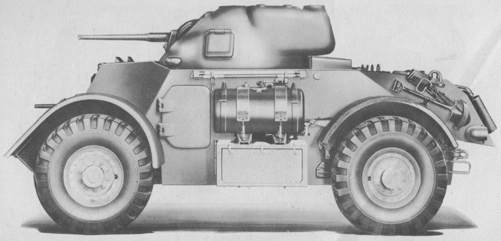
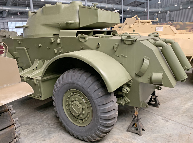
The side door can be better seen in this angle. A shovel and a machine gun tripod and pintle are stowed above and behind the rear wheel. A rammer staff resides above the jettison fuel tank. (Picture from TM 9-741 Medium Armored Car T17E1.)
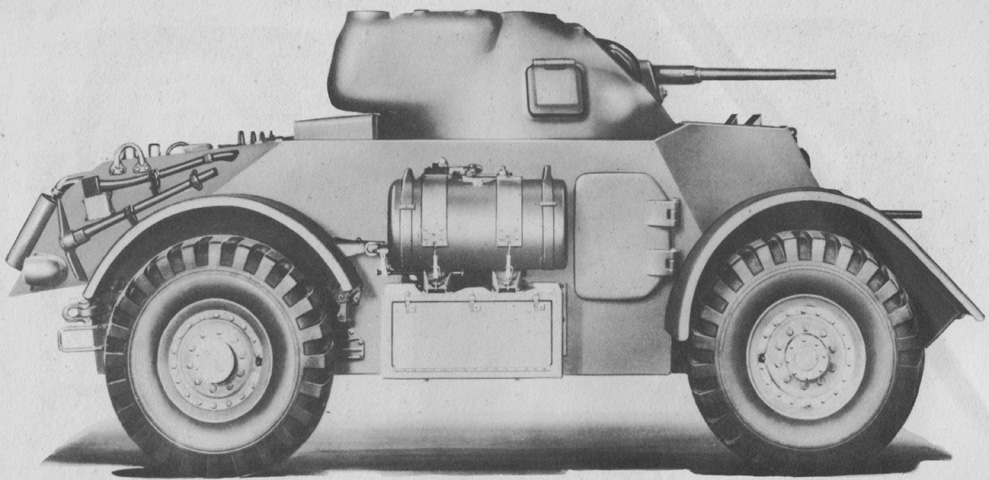
A second jettison fuel tank was mounted on the opposite side. (Picture from TM 9-741 Medium Armored Car T17E1.)
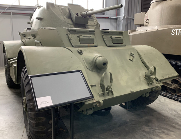
The asymmetrical nature of the turret can be seen in this head-on view. (Picture from TM 9-741 Medium Armored Car T17E1.)
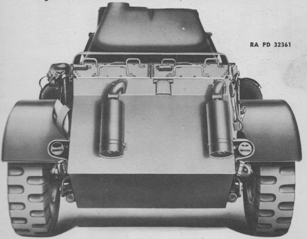
The engine mufflers were mounted on the vehicle's rear slope, and the handles for the engine compartment doors can be seen. The right-hand light housing contains a blackout tail lamp and a stop lamp. The left-hand light housing has a blackout tail lamp, a service tail lamp, and a stop lamp. (Picture from TM 9-741 Medium Armored Car T17E1.)
In addition to the luggage boxes on the lower hull sides, a stowage box could be mounted on the turret rear.
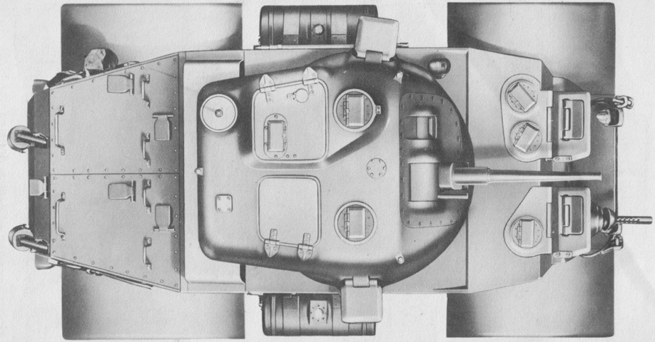
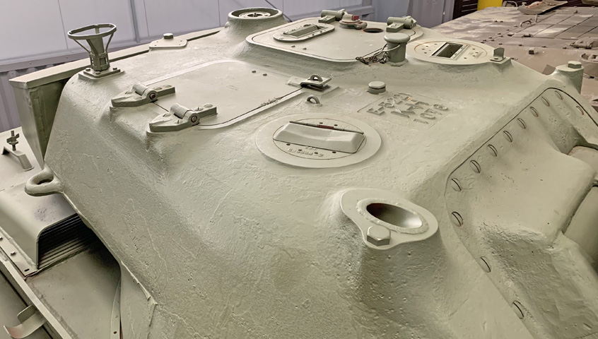
This early car lacks the smoke mortar found in the turret roof of later vehicles. Periscopes M6 were provided for the driver (2), assistant driver, and on each side of the turret roof and in the gunner's hatch. Behind this hatch is the base for an antenna MP 37; an antenna MP 48 could be fitted near the front of the turret roof. (Picture from TM 9-741 Medium Armored Car T17E1.)
This later-production machine was equipped with a 2" smoke mortar, the aperture for which can be seen at the right front corner of the turret roof.
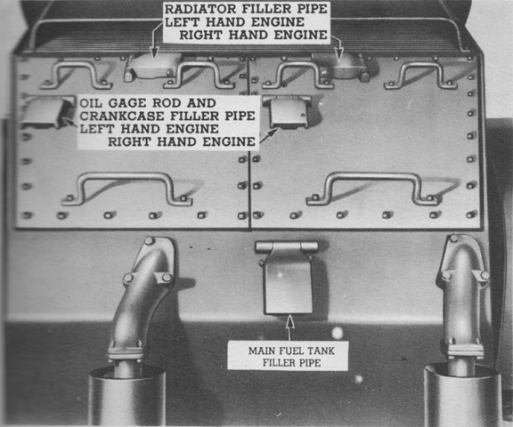
The filler pipes located on the rear of the vehicle are labeled in this picture. (Picture from TM 9-741 Medium Armored Car T17E1.)
A closer view of the rear deck and the protected engine air intake under the stowage box is provided here.
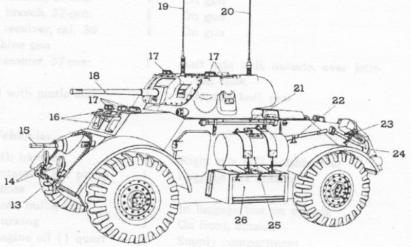
Equipment on the left side of the car is detailed here. 13. Towing cable. 14. Headlight socket plugs. 15. .30 cal machine gun and muzzle cover. 16. Front vision doors. 17. Periscopes M6. 18. 37 m/m gun M6 and muzzle cover. 19. Antenna MP 48. 20. Antenna MP 37. 21. Rammer staff. 22. Pick. 23. Tripod with pintle. 24. Shovel. 25. Jettison tank. 26. Luggage box: spare bulbs box; collapsible bucket; rations (Type C); blanket rolls; tire pump and hose. (Picture from TM 9-741 Medium Armored Car T17E1.)
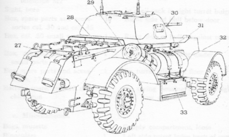
Equipment on the right side of the car is detailed here. 27. Axle [sic]. 28. Crowbar. 29. Camouflage net and tarpaulin. 30. Cal .30 machine gun and muzzle cover. 31. Antenna sections. 32. Jettison tank. 33. Luggage box: tire chains; flexible nozzle (fuel can); heavy tools; wrench and handle; jack and handle. (Picture from TM 9-741 Medium Armored Car T17E1.)
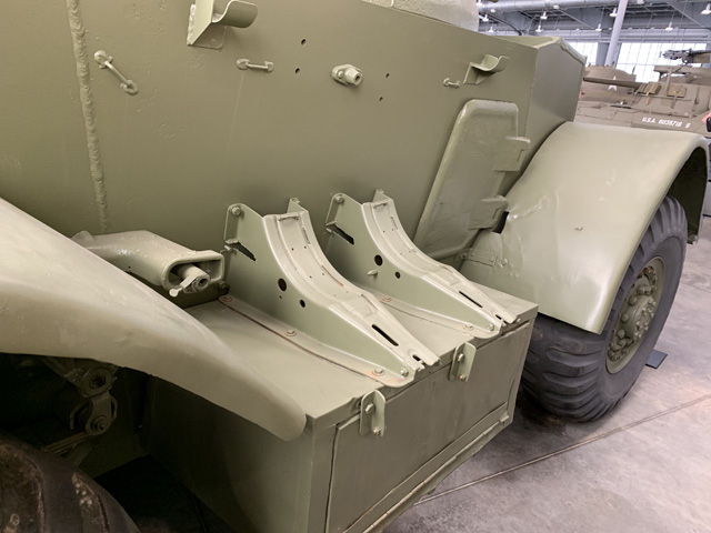
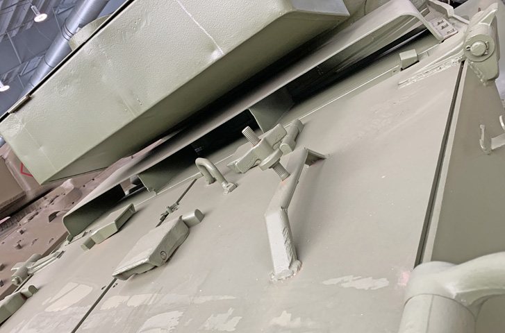
Details of the right side luggage box and the supports for the jettisonable fuel tank can be seen here.
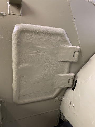
A door was found on each side of the hull. The locking bolts for the doors were held in the off position with a spring-loaded detent ball.
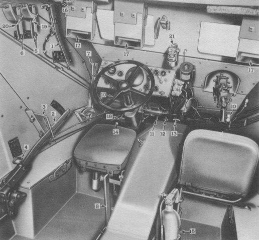
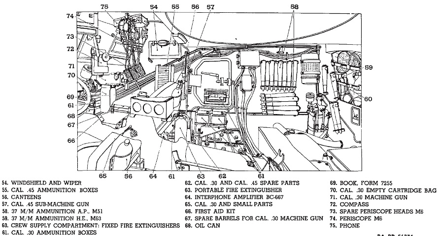
The driver's compartment is shown here. 1. Transmission manual control lever. 2. Transfer case shift lever. 3. Transfer case shift lever gate plate. 4. Engine selector lever. 5. Carburetor choke levers--left and right engines. 6. Hand throttles--left and right engines. 7. Hand brake lever. 8. Transfer case front axle lever. 10. Head lamp release buttons. 11. Brake pedal. 12. Accelerator pedal. 13. Steering gear motor switch. 14. Siren foot control. 15. Hand fire extinguisher. 16. Fire extinguishing system control handles. 17. Periscopes. 18. Hand brake assist pedal. 19. Choke levers clamp bolt. 20. Throttle levers clamp bolt. 21. Compass. (Picture from TM 9-741 Medium Armored Car T17E1.)
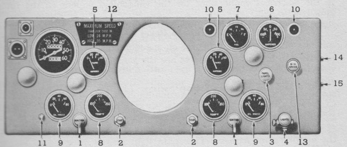
The driver's instrument panel is labeled. 1. Ignition switches--left and right engines. 2. Starting buttons--left and right engines. 3. Instrument panel light switch. 4. Lighting switch. 5. Ammeters--left and right engines. 6. Ammeter--total output, both generators. 7. Fuel gage--main fuel tank. 8. Engine temperature indicators--left and right engines. 9. Oil pressure gages--left and right engines. 10. Electrical sockets--left and right windshield wipers. 11. Speedometer trip mileage reset. 12. Speed caution plate. 13. Blackout driving lamp lighting switch circuit. 14. Lighting switch circuit breaker reset button. 15. Fuel pump circuit breaker reset button. (Picture from SNL G-122 Service Parts Catalog for Chevrolet Medium Armored Car M6.)
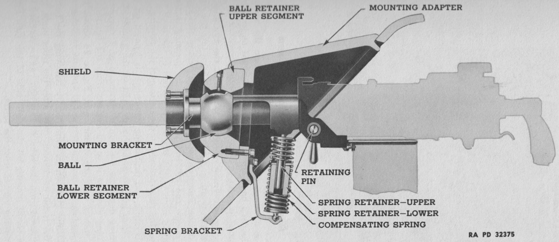
A cross-section of the assistant driver's machine gun mount is shown here. A screw in the upper segment of the ball retainer engaged a milled slot in the ball to ensure that the machine gun could not rotate around its axis in the mount. Due to the majority of the gun's weight being behind the ball, a spring was installed to help compensate for the uneven weight distribution. (Picture from TM 9-741 Medium Armored Car T17E1.)
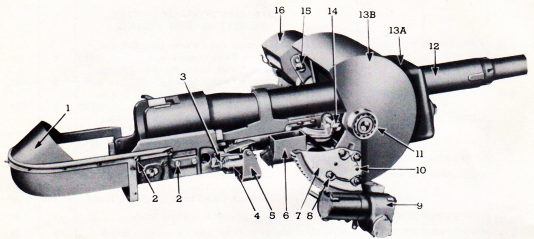
The combination gun mount M24 is shown here from the right with its front plate attached. 1. Breech guard. 2. Screw/washer. 3. Bracket. 4. Solenoid. 5. Bracket. 6. Chute. 7. Sector. 8. Bolt. 9. Elevating mechanism. 10. Pin. 11. Bearing. 12. Sleigh. 13. Rotor unit, composed of: 13A. Shield. 13B. Rotor. 14. Pin assy. 15. Cam/nut. 16. Periscope mounting. (Picture from SNL G-122 Service Parts Catalog for Chevrolet Medium Armored Car M6.)
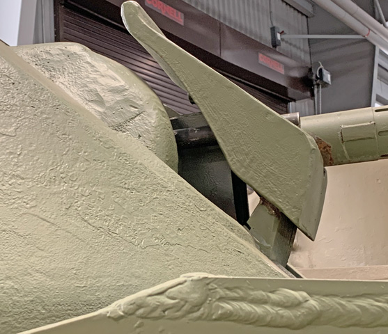
The profile of the later M24A1's gun shield is illustrated by this image, and the 37mm and coaxial guns can be seen protruding through it.
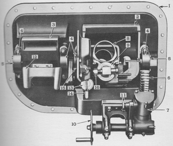
The inside of the gun mount is detailed in this image. 1. Front plate. 2. Rotor. 3. Periscope holder. 4. Trunnion bearing cap. 5. Trunnion bearing thrust plate. 6. Sector. 7. Worm gear housing. 8. Sleigh. 9. Recoil mechanism. 10. Handwheel. 11. Lock plunger. 12. Head rest. 13. Gun firing solenoid - 37 mm gun. 14. Firing lever. 15. Safety. 16. Attaching bolt 37 mm. gun. (Picture from TM 9-741 Medium Armored Car T17E1.)
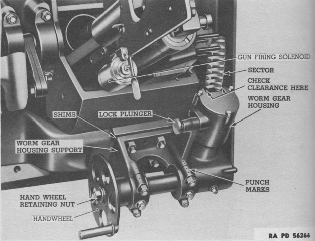
A closer look at the elevation system is provided in this image. (Picture from TM 9-741 Medium Armored Car T17E1.)
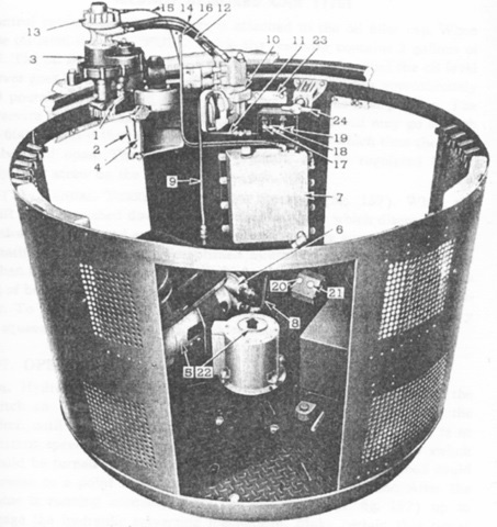
The parts of the turret traverse system are diagrammed in this picture. The gunner could choose manual traverse by moving the traverse shift lever down, or hydraulic traverse by moving the shift lever up. 1. Traverse shift lever. 2. Handwheel brake trigger. 3. Traversing gear box. 4. Handwheel crank. 5. Electric motor. 6. Hydraulic pump. 7. Oil reservoir. 8. Suction hose. 9. Pressure line. 10. Hydraulic control valve. 11. Exhaust line. 12. Short motor hose. 13. Hydraulic motor. 14. Long motor hose. 15. Motor drain line. 16. Reservoir breather. 17. Turret motor switch. 18. Dome lamp switch. 19. Foot firing safety switch. 20. Foot firing switch (37 mm.). 21. Foot firing switch (30 cal.). 22. Vehicle directional indicator. 23. Turret direction indicator scale. 24. Turret lock. (Picture from TM 9-741 Medium Armored Car T17E1.)
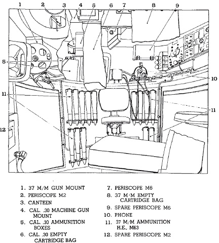
An illustration of stowage on the left side of the hull is provided here. (Picture from TM 9-741 Medium Armored Car T17E1.)
This is stowage on the right side of the hull. (Picture from TM 9-741 Medium Armored Car T17E1.)
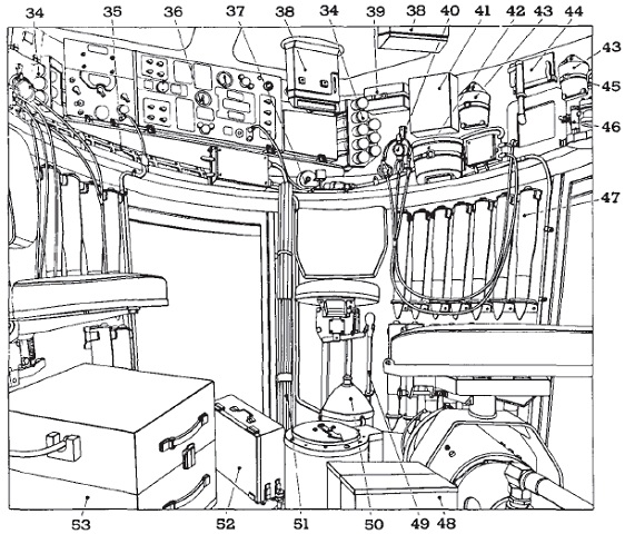
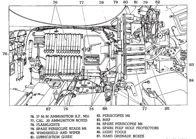
The left side of the turret basket is shown in this drawing. 34. 37 m/m cannister [sic] M2 ammunition. 35. Spare periscope heads M2 and M6. 36. Radio SCR-506 or SCR-508. 37. Spotlight handle and reel. 38. Periscopes M6. 39. Cal. .30 and 37mm small parts. 40. Phone. 41. Spare periscope M6. 42. Binoculars. 43. Canteens. 44. Map. 45. Compass. 46. Flashlight. 47. 37 m/m ammunition A.P., M51. 48. Hand grenade boxes. 49. Spot light shaft. 50. Spot light. 51. Signal flags. 52. 37 m/m spare parts. 53. Radio SCR-510. (Picture from TM 9-741 Medium Armored Car T17E1.)
This is the right side of the turret basket. (Picture from TM 9-741 Medium Armored Car T17E1.)
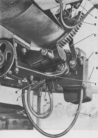
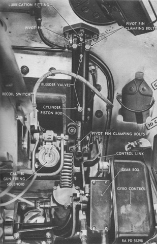
Various parts of the gyrostabilizer found on early vehicles are shown here. The gun mount elevating gear is visible. A. Piston and cylinder assembly. B. Piston rod end mounting bracket. C. Control link. D. Gear box. E. Gyro control unit. F. Mounting bracket. G. Flexible shaft. H. Disengaging switch. J. Switch plunger. K. Flexible shaft gear box. (Picture from TM 9-741 Medium Armored Car T17E1.)
Another view of the installed stabilizer components is provided in this image. (Picture from TM 9-741 Medium Armored Car T17E1.)
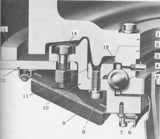
This is a cross-section of the turret ring. The turret ball ring assembly was made of one hundred twenty 1¼" (3.18cm) balls and twelve ball retainers. 1. Turret. 2. Ball inner race. 3. Lubrication fitting. 4. Ball. 5. Turret basket. 6. Turret direction indicator scale. 7. Indicator scale mounting block. 8. Ball ring pad retainer. 9. Ball ring pad. 10. Outer race and ring gear. 11. Ball ring. 12. Hull. 13. Hull front roof plate turret ring guard. 14. Ball outer race attaching bolt. 15. Ball retainer. (Picture from TM 9-741 Medium Armored Car T17E1.)
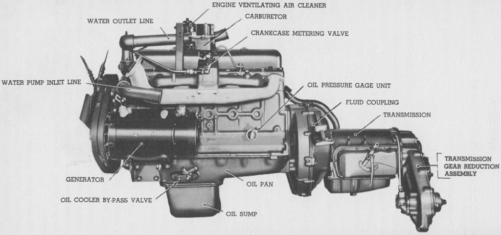
The left engine's left side is shown here; the flywheel and transmission side of the engines faced toward the vehicle's center. Each engine displaced 269.52in³ (4416.6cm³) with a bore of 3.78125" (9.60438cm) and a stroke of 4" (10cm). One engine with accessories weighed 830lb (380kg) and had an oil capacity of 8qt (7.6L). (Picture from TM 9-741 Medium Armored Car T17E1.)
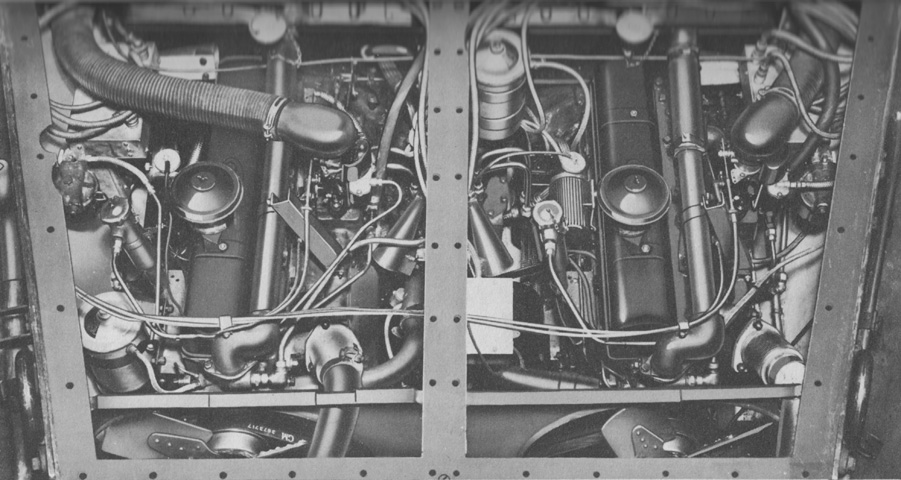
This image shows engines installed with the rear deck plates removed. (Picture from TM 9-741 Medium Armored Car T17E1.)
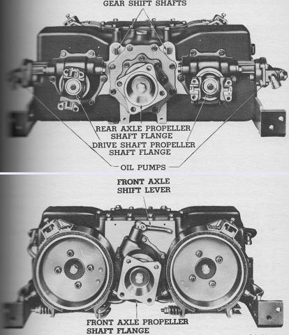
The engine end of the transfer case and brake assembly is shown in this picture. It was essentially a two-speed transmission that connected the engines' two power lines with the front and rear axles. Separate shifters allowed the engagement of the front axle and the ability to change between high and low speeds. The transfer case speed selector could be shifted to high or low from a central position to affect both engines, or off to either side where it would only affect a single engine. This enabled the use of a single engine if necessary. At the front end of each transfer case propeller shaft was mounted a parking brake. (Picture from TM 9-741 Medium Armored Car T17E1.)
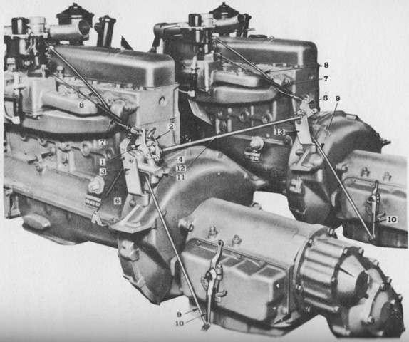
The foot throttle was hydraulically operated, using the same fluid reservoir as the brake system. Control rods connected the engines, carburetors, and transmissions, and these rods required synchronization. 1. Slave cylinder idler lever. 2. Cross shaft accelerator lever. 3. Slave cylinder support bracket. 4. Cross shaft coupling lever. 5. Cross shaft operating lever. 6. Slave cylinder coupling lever return spring. 7. Throttle rod return springs. 8. Throttle rods. 9. Transmission throttle control rods. 10. Throttle valve levers. 11. Slave cylinder. 12. Cross shaft. 13. Cross shaft support bracket. (Picture from TM 9-741 Medium Armored Car T17E1.)
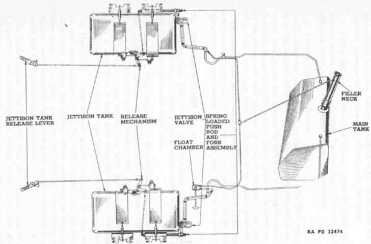
The fuel system is sketched here, including the two jettison tanks. The jettison tanks were each 25 or 38 gallons (95 or 140L). (Picture from TM 9-741 Medium Armored Car T17E1.)
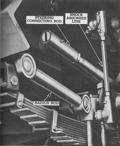
The front and rear semi-elliptic leaf springs were 50.5" (128cm) long and 3.5" (8.9cm) wide. The radius rods transmitted the drive from the wheels to the hull. The rods were tubular with sealed, lubricated ball studs at each end, which were attached to brackets on the axle housings and hull sides. The shock absorbers were hydraulic double-acting units. (Picture from TM 9-741 Medium Armored Car T17E1.)
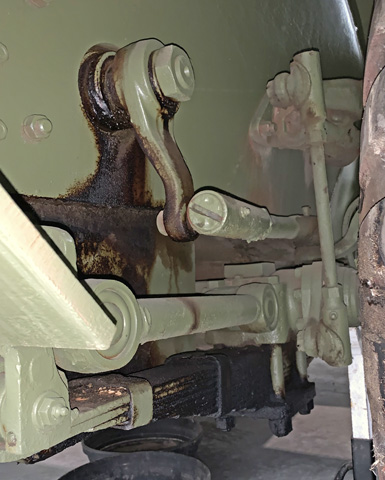
The radius rod, leaf spring assembly, shock absorber, and pitman arm attached to the steering connecting rod can all be seen here.
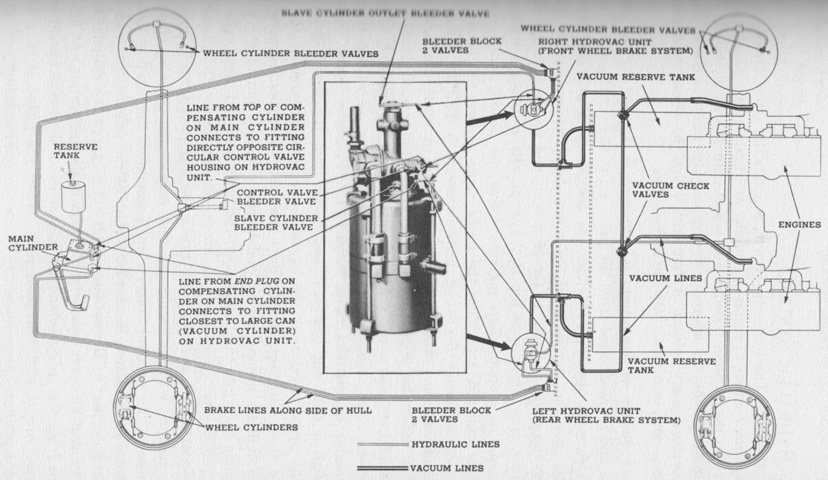
The layout of the brake system is sketched here. In addition to the hydraulic system, a Hydrovac unit used vacuum to assist the driver with brake application. (Picture from TM 9-741 Medium Armored Car T17E1.)
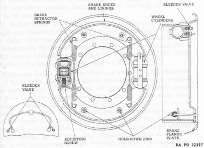
The construction of a brake at the wheel is given in this diagram. (Picture from TM 9-741 Medium Armored Car T17E1.)
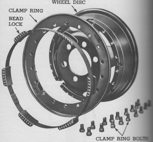
The wheels had divided rims, and a bead lock assembly was inserted on the rim between the beads of the casing to prevent the tire's sidewalls from collapsing if it needed to be run while flat. (Picture from TM 9-741 Medium Armored Car T17E1.)
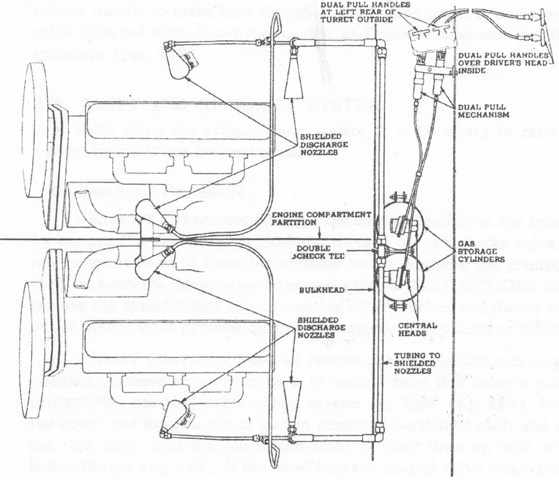
The fire extinguishing system is diagrammed in this sketch. Two cylinders containing 10lb (4.5kg) of Lux or carbon dioxide were used to suffocate fires in the engine compartment. These could be actuated by pulling handles located on the hull exterior behind the turret and above the driver, or via the control heads on the cylinders themselves. A separate handle actuated its respective cylinder at the outer hull and driver's locations. A 4lb (2kg) portable extinguisher was also carried. (Picture from TM 9-741 Medium Armored Car T17E1.)
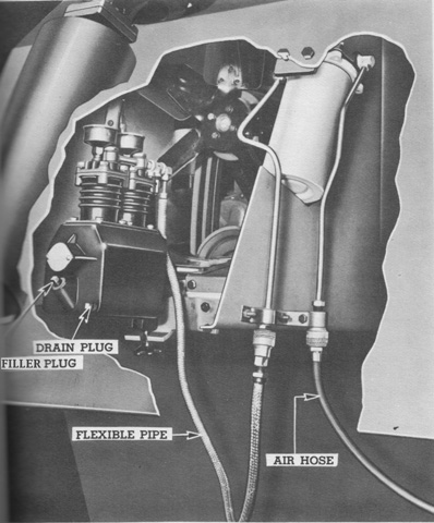
A powered air pump was stowed in a metal box in the side luggage box. It was a 2-cylinder engine-driven pump with the necessary attaching clamps and drive shaft, a flexible metal pipe to connect the pump to the air filter (the white cylinder in the image), and 22' (6.7m) of flexible airhose. When needed, the pump was installed on a bracket under the rear armor plate. The pump's propeller shaft was then engaged with a special drive cup on the engine crankshaft. The engine was run at 600-800rpm to fill the tires. (Picture from TM 9-741 Medium Armored Car T17E1.)
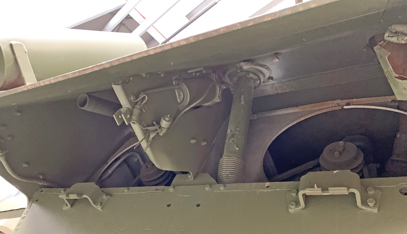
The underside of the rear armor plate is seen here, with the left engine exhaust at the upper left. Each engine had its own 25-quart (24L) cooling system, and the engines' fan shrouds and pulleys are also visible. The belts were not interchangeable between the left and right engine fans. The air filter for the powered air pump was permanently mounted adjacent to the fuel filler neck, inside the vertical support attached to the upper hull rear plate. The filter's inlet and outlet pipes are attached to the near side of the vertical support.
