


| M36: General | |||
| Date of first acceptance | April 1944 | Total acceptances | 1,413 |
| Manufacturers |
|
Crew |
|
| M36: Dimensions | |||
| Combat weight | 63,000lbs 29,000kg |
Height over AAMG | 129" 328cm |
| Length without gun | 235.1" 597.2cm |
Gun overhang forward without muzzle brake | 58.8" 149cm |
| Width | 120" 305cm |
Tread | 83" 211cm |
| Ground clearance | 17" 43cm |
Fire height | 85" 220cm |
| Turret ring diameter | 69" 175cm |
Ground pressure, zero penetration | 12.9psi .906kg/cm² |
| M36: Armament | |||||
| Type | Mount | Ammunition | Traverse | Max traverse rate | Elevation |
| 90mm Gun M3 | M4 in turret | 47 rounds (11 ready) |
360° (manual and hydraulic) |
24°/sec | +20° to -10° (manual) |
| .50cal M2HB MG | Concentric ring mount D94428 on turret | 1,000 rounds | 360° (manual) |
-- | +85° to -13° (manual) |
| Aiming equipment | |||||
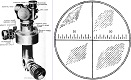
| Telescope M71C, M76D, M76F, M76P, or M83C; panoramic telescope M12 for gunner | |||||
| M36: Armor | ||
| Assembly | ||
| Welding | ||
| Hull | ||
| Rolled and cast homogeneous steel | ||
| Location | Thickness | Angle from vertical |
| Upper front | 1.5" 3.8cm |
55° |
| Lower front | 2.0" 5.1cm |
0° to 56° |
| Upper sides | .75" 1.9cm |
38° |
| Lower sides | 1.0" 2.5cm |
0° |
| Upper rear | .75" 1.9cm |
38° |
| Lower rear | 1.0" 2.5cm |
0° |
| Front top | .75" 1.9cm |
90° |
| Rear top | .375" .953cm |
90° |
| Floor | .50" 1.3cm |
90° |
| Turret | ||
| Rolled and cast homogeneous steel | ||
| Location | Thickness | Angle from vertical |
| Front (gun shield) | 3.0" 7.6cm |
0° |
| Sides | 1.25" 3.18cm |
5° |
| Rear | 1.75" to 5.0" 4.45cm to 13cm |
0° |
| Top | .375" to 1.0" .953cm to 2.5cm |
90° |
| M36: Automotive | |||||
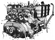
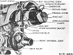
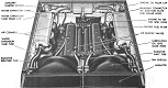
| Engine | Ford GAA; 8 cylinder, 4 cycle, 60� vee gasoline | ||||
| Horsepower | Net: 450@2,600rpm Gross: 500@2,600rpm |
Torque | Net: 950 ft-lb@2,200rpm Gross: 1,040 ft-lb@2,200rpm |
Fuel capacity | 192gal 727L |
| Transmission | Synchromesh, 5 speeds forward, 1 reverse | ||||
| Steering | Controlled differential, steering levers | ||||
| Brakes | Mechanical, external contracting | ||||
| M36: Suspension | ||
| Type | Road wheels | Track return rollers |
| Vertical volute spring | 3 bogies/track; 2 wheels/bogie |
1 at rear of each bogie |
| Drive sprockets | Idlers | Shock absorbers | 13-tooth front drive | Adjustable at rear of track | None |
| M36: Track | |||||||
| T48 | |||||||
| Outside guide, double pin, chevron, rubber | |||||||
| Width | 16.56" 42.06cm |
Pitch | 6" 15cm |
Shoes/track | 79 | Ground contact length | 147" 373cm |
| T49 | |||||||
| Outside guide, double pin, parallel bar, steel | |||||||
| Width | 16.56" 42.06cm |
Pitch | 6" 15cm |
Shoes/track | 79 | Ground contact length | 147" 373cm |
| T51 | |||||||
| Outside guide, double pin, smooth, rubber | |||||||
| Width | 16.56" 42.06cm |
Pitch | 6" 15cm |
Shoes/track | 79 | Ground contact length | 147" 373cm |
| T54E1 | |||||||
| Outside guide, double pin, chevron, steel | |||||||
| Width | 16.56" 42.06cm |
Pitch | 6" 15cm |
Shoes/track | 79 | Ground contact length | 147" 373cm |
| M36: Performance | |||
| Max level road speed | 26mph 42kph |
Max trench | 90" 230cm |
| Max grade | 60% | Max vertical obstacle | 24" 61cm |
| Min turning diameter | 62' 19m |
Max fording depth | 36" 91cm |
| Cruising range | ~150mi, roads ~240km, roads |
||
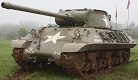
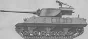
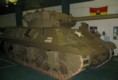
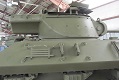
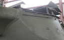
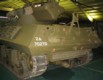
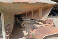
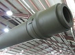
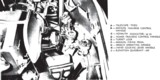
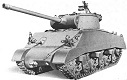
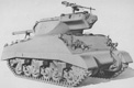
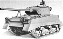
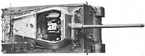
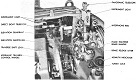
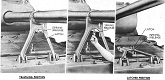
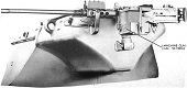
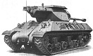
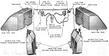
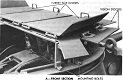
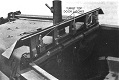
The 90mm GMC M36 was completed by installing a new turret on the hull of the 3" GMC M10A1; both new production hulls and M10A1s returning from the field were converted. Muzzle brakes were able to be fitted to all M36s except the first 600, since these early vehicles lacked the new equilibrator, stronger elevation mechanism, and stronger gun travel lock that were prerequisites for muzzle brake installation. Like other US tank destroyers, the M36 was open-topped, but a folding armored roof kit was developed to protect the crew from artillery airbursts. The kit still allowed 360° visibility, however, since it was elevated a short distance from the top of the turret.
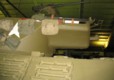
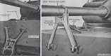
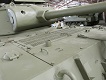
The M36 had a large bustle on the turret rear that acted both as a counterweight to the 90mm gun as well as holding eleven 90mm ready rounds. The gun shield on the M36 was rounded, compared to the more pointed appearance of the M10's gun shield. Due to the high ground pressure, later M36s were fitted with the spaced-out suspension that was tested in the -E9 series of M4 Sherman which allowed extended end connectors to be attached to both the inside and outside of each track.
| M36B1: General | |||
| Date of first acceptance | October 1944 | Total acceptances | 187 |
| Manufacturer | Fisher Tank Arsenal | Crew |
|
| M36B1: Dimensions* | |||
| Loaded weight | ~68,000lbs ~31,000kg |
Height over-all | 104.625" 265.746cm |
| Length over-all with gun in firing position | 294.5" 748.0cm |
Length over-all with gun in traveling position | 286" 726cm |
| Width with sandshields | 104.5" 265.4cm |
Tread | 83" 211cm |
| Ground clearance | 17.125" 43.498cm |
Turret ring diameter | 69" 175cm |
| M36B1: Armament | |||||
| Type | Mount | Ammunition | Traverse | Max traverse rate | Elevation |
| 90mm Gun M3 | M4 or M4A1 in turret | 47 rounds (11 ready) |
360° (manual and hydraulic) |
24°/sec | M4: +30° to -10°; M4A1: +20° to -10° (manual) |
| .50cal M2HB MG | Concentric ring mount D94428 on turret | 1,000 rounds | 360° (manual) |
-- | +85° to -13° (manual) |
| .30cal M1919A4 MG | Ball mount D51070 in right bow | 2,000 rounds | 20° left, 25° right (manual) |
-- | +20° to -10° (manual) |
| Aiming equipment | |||||
| Telescope M71C, M76D, M76F, M76P, or M83C; panoramic telescope M12 for gunner | |||||
| M36B1: Armor | ||
| Assembly | ||
| Welding | ||
| Hull | ||
| Rolled and cast homogeneous steel | ||
| Location | Thickness | Angle from vertical |
| Upper front | 2.5" 6.4cm |
47° |
| Lower front | 4.25" to 2.0" 10.8cm to 5.1cm |
0° to 56° |
| Sides | 1.5" 3.8cm |
0° |
| Rear | 1.5" 3.8cm |
10° to 22° |
| Top | .75" 1.9cm |
83° to 90° |
| Front floor | 1.0" 2.5cm |
90° |
| Rear floor | .50" 1.3cm |
90° |
| Turret | ||
| Rolled and cast homogeneous steel | ||
| Location | Thickness | Angle from vertical |
| Front (gun shield) | 3.0" 7.6cm |
0° |
| Sides | 1.25" 3.18cm |
5° |
| Rear | 1.75" to 5.0" 4.45cm to 13cm |
0° |
| Top | .375" to 1.0" .953cm to 2.5cm |
90° |
| M36B1: Automotive | |||||
| Engine | Ford GAA; 8 cylinder, 4 cycle, 60� vee gasoline | ||||
| Horsepower | Net: 450@2,600rpm Gross: 500@2,600rpm |
Torque | Net: 950 ft-lb@2,200rpm Gross: 1,040 ft-lb@2,200rpm |
Fuel capacity | 168gal 636L |
| Transmission | Synchromesh, 5 speeds forward, 1 reverse | ||||
| Steering | Controlled differential, steering levers | ||||
| Brakes | Mechanical, external contracting | ||||
| M36B1: Suspension | ||
| Type | Road wheels | Track return rollers |
| Vertical volute spring | 3 bogies/track; 2 wheels/bogie |
1 at rear of each bogie |
| Drive sprockets | Idlers | Shock absorbers | 13-tooth front drive | Adjustable at rear of track | None |
| M36B1: Track | |||||||
| T48 | |||||||
| Outside guide, double pin, chevron, rubber | |||||||
| Width | 16.56" 42.06cm |
Pitch | 6" 15cm |
Shoes/track | 79 | Ground contact length | 147" 373cm |
| T49 | |||||||
| Outside guide, double pin, parallel bar, steel | |||||||
| Width | 16.56" 42.06cm |
Pitch | 6" 15cm |
Shoes/track | 79 | Ground contact length | 147" 373cm |
| T51 | |||||||
| Outside guide, double pin, smooth, rubber | |||||||
| Width | 16.56" 42.06cm |
Pitch | 6" 15cm |
Shoes/track | 79 | Ground contact length | 147" 373cm |
| T54E1 | |||||||
| Outside guide, double pin, chevron, steel | |||||||
| Width | 16.56" 42.06cm |
Pitch | 6" 15cm |
Shoes/track | 79 | Ground contact length | 147" 373cm |
| M36B1: Performance | |||
| Max level road speed | 26mph sustained 42kph sustained |
Max trench | 90" 230cm |
| Max grade | 60% | Max vertical obstacle | 24" 61cm |
| Min turning diameter | 62' 19m |
Max fording depth | 36" 91cm |
| Cruising range | ~100mi, roads ~160km, roads |
||
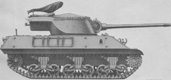
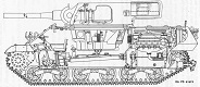
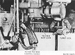
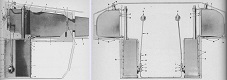
The M36B1 was constructed by mating the 90mm M36 gun turret with the hull of the late-production M4A3 Sherman. Internal stowage was rearranged to accommodate the larger 90mm rounds, and contrary to other tank destroyers the bow machine gun was retained.


| M36B2: General | |||
| Date of first acceptance | May 1945 | Total acceptances | 724 |
| Manufacturer |
|
Crew |
|
| M36B2: Dimensions* | |||
| Fighting weight | 66,000lbs 30,000kg |
Height over-all | 123.6875" 314.1663cm |
| Length over-all | 293.875" 746.443cm |
Width with sandshields | 120" 305cm |
| Tread | 91" 230cm |
Ground clearance | 18.375" 46.673cm |
| Turret ring diameter | 69" 175cm |
Ground pressure, zero penetration | 15psi 1.1kg/cm² |
| M36B2: Armament | |||||
| Type | Mount | Traverse | Max traverse rate | Elevation | |
| 90mm Gun M3 | M4A1 in turret | 360° (manual and hydraulic) |
24°/sec | +20° to -10° (manual) |
|
| .50cal M2HB MG | Concentric ring mount D94428 on turret | 360° (manual) |
-- | +85° to -13° (manual) |
|
| Aiming equipment | |||||
| Telescope M71C, M76D, M76F, M76P, or M83C; panoramic telescope M12 for gunner | |||||
| M36B2: Armor | ||
| Assembly | ||
| Welding | ||
| Hull | ||
| Rolled and cast homogeneous steel | ||
| Location | Thickness | Angle from vertical |
| Upper front | 1.5" 3.8cm |
55° |
| Lower front | 2.0" 5.1cm |
0° to 56° |
| Upper sides | .75" 1.9cm |
38° |
| Lower sides | 1.0" 2.5cm |
0° |
| Upper rear | .75" 1.9cm |
38° |
| Lower rear | 1.0" 2.5cm |
0° |
| Front top | .75" 1.9cm |
90° |
| Rear top | .375" .953cm |
90° |
| Floor | .50" 1.3cm |
90° |
| Turret | ||
| Rolled and cast homogeneous steel | ||
| Location | Thickness | Angle from vertical |
| Front (gun shield) | 3.0" 7.6cm |
0° |
| Sides | 1.25" 3.18cm |
5° |
| Rear | 1.75" to 5.0" 4.45cm to 13cm |
0° |
| Top | .375" to 1.0" .953cm to 2.5cm |
90° |
| M36B2: Automotive | |||||
| Engine | General Motors 6046; 12 cylinder (6/engine), 2 cycle, twin in-line diesel | ||||
| Horsepower | Net: 375@2,100 crankshaft rpm (188/engine) Gross: 410@2,900 propeller shaft rpm (205/engine) |
Torque | Net: 1,000 ft-lb@1,400 crankshaft rpm (500/engine) Gross: 885 ft-lb@1,900 propeller shaft rpm (443/engine) |
Fuel capacity | 165gal 625L |
| Transmission | Synchromesh, 5 speeds forward, 1 reverse | ||||
| Steering | Controlled differential, steering levers | ||||
| Brakes | Mechanical, external contracting | ||||
| M36B2: Suspension | ||
| Type | Road wheels | Track return rollers |
| Vertical volute spring | 3 bogies/track; 2 wheels/bogie |
1 at rear of each bogie |
| Drive sprockets | Idlers | Shock absorbers | 13-tooth front drive | Adjustable at rear of track | None |
| M36B2: Track | |||||||
| T48 | |||||||
| Outside guide, double pin, chevron, rubber | |||||||
| Width | 16.56" 42.06cm |
Pitch | 6" 15cm |
Shoes/track | 79 | Ground contact length | 147" 373cm |
| T49 | |||||||
| Outside guide, double pin, parallel bar, steel | |||||||
| Width | 16.56" 42.06cm |
Pitch | 6" 15cm |
Shoes/track | 79 | Ground contact length | 147" 373cm |
| T51 | |||||||
| Outside guide, double pin, smooth, rubber | |||||||
| Width | 16.56" 42.06cm |
Pitch | 6" 15cm |
Shoes/track | 79 | Ground contact length | 147" 373cm |
| T54E1 | |||||||
| Outside guide, double pin, chevron, steel | |||||||
| Width | 16.56" 42.06cm |
Pitch | 6" 15cm |
Shoes/track | 79 | Ground contact length | 147" 373cm |
| M36B2: Performance | |||
| Max level road speed | 25mph sustained 40kph sustained |
Max trench | 90" 230cm |
| Max grade | 50% | Max vertical obstacle | 19" 48cm |
| Min turning diameter | 62' 19m |
Max fording depth | 42" 110cm |
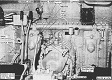
Eventually supplies of M10A1 hulls were used up, so diesel-powered M10 hulls were converted to the 90mm turret, yielding M36B2.


*Dimensional and performance information for the M36 was reprinted with permission from Hunnicutt's Sherman, while that for the M36B1 and M36B2 came from their respective technical manuals. Any inconsistencies should presumably simply be chalked up to differences in source data and not to actual differences in production.
