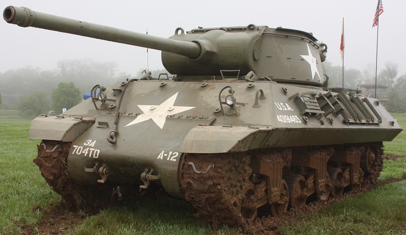
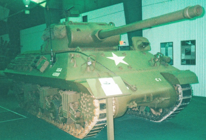
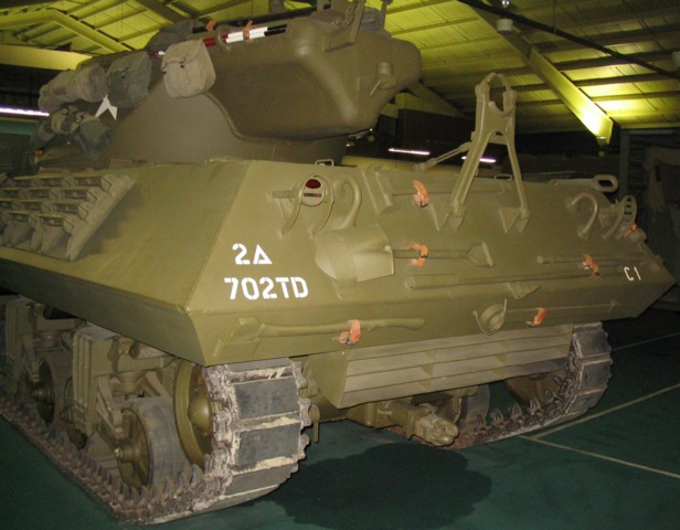
90mm Gun Motor Carriage M36 at the US Army Heritage and Education Center at Carlisle Barracks.
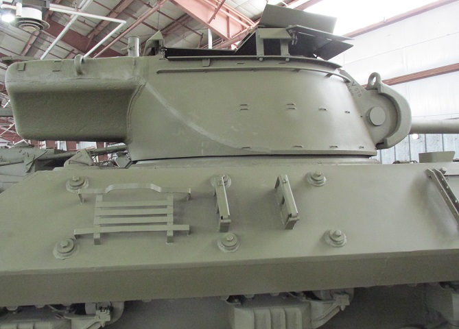
The large 90mm gun on this vehicle is imposing and indicates the power of these tank destroyers. As no coaxial machine gun was mounted and the gunner was stationed to the gun's right side, the left side of the gun shield was bereft of apertures. Track grousers and spare track shoes are stowed on the hull sides, and bosses for auxiliary armor can be seen on on the hull front and sides. (Photo by Richard S. Eshleman.)
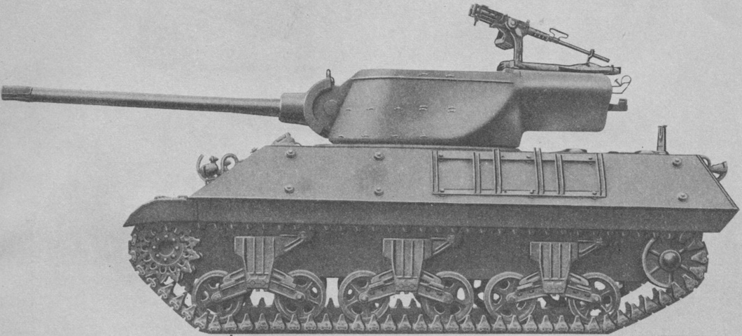
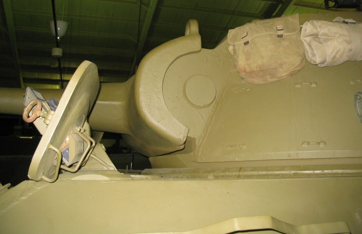
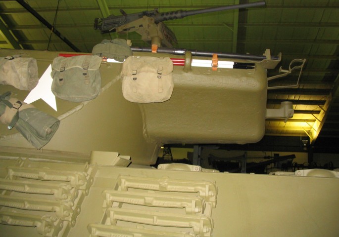
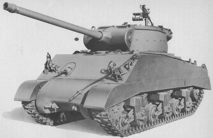
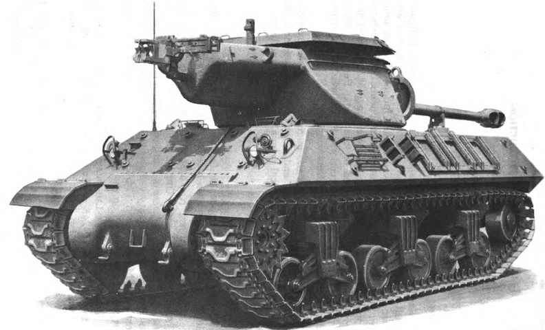
The long turret bustle is obvious from the side, and the semicircular cross-section of the gun shield can easily be seen. The .50cal machine gun barrel is secured in its travel lock, while stowage mounts for the machine gun are attached to the turret bustle rear. This early vehicle retains a gun rest on the rear hull deck and bosses for auxiliary armor on the hull sides. (Picture from ORD 8-9 SNL G-210 Field and Base Maintenance Spare Parts and Equipment and List of All Service Parts for Carriage, Motor, 90-mm Gun, M36.)
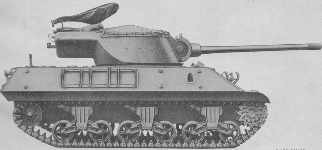
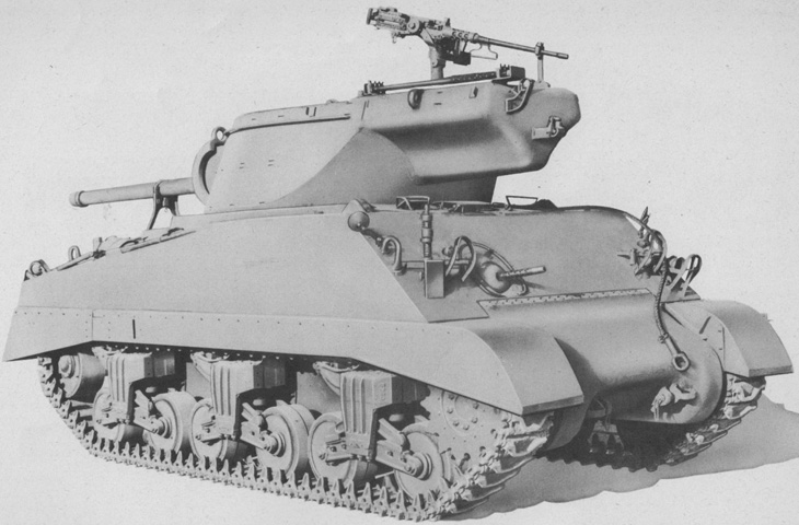
Canvas covers have been installed over the machine gun and open turret top. A radio antenna mount is present in the hull side just to the rear of the forward auxiliary armor bosses. (Picture from ORD 8-9 SNL G-210 Field and Base Maintenance Spare Parts and Equipment and List of All Service Parts for Carriage, Motor, 90-mm Gun, M36.)
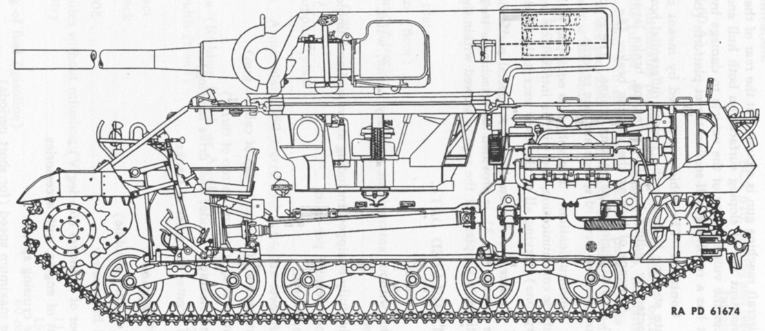
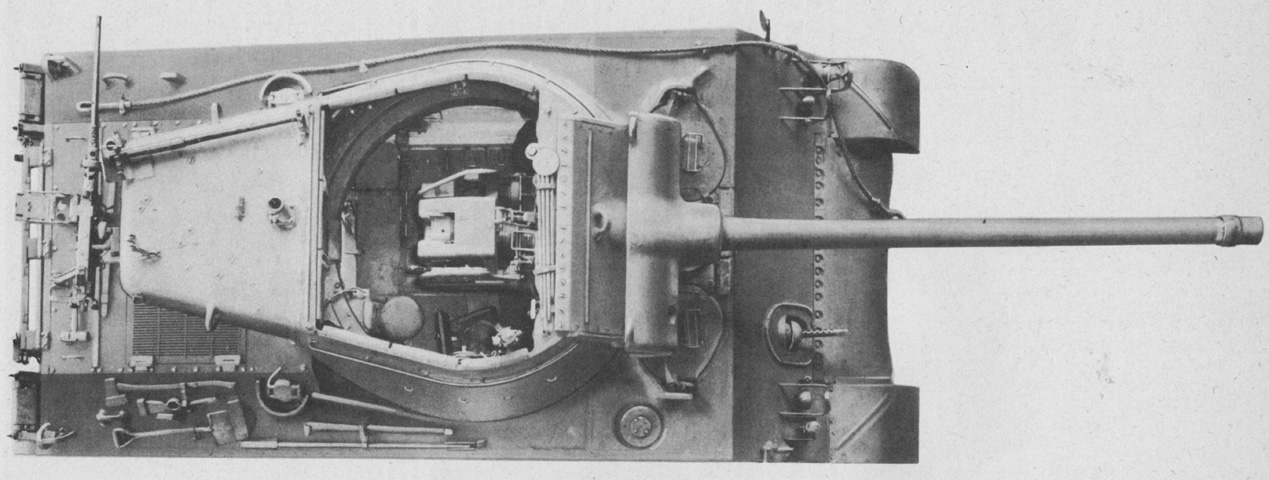
The internal layout can be seen in this cross-section. (Picture from TM 9-758 90-mm Gun Motor Carriage T71.)
This vehicle was based on a late-production hull, since the auxiliary armor bosses have been omitted from the hull sides. The driver's periscope in its open hatch door can be seen. The vehicle's siren is placed just outboard of the left-hand headlight group.
The semi-circular gun shield helps differentiate this vehicle from the M10, as the M10's gun shield was more pyramidal.
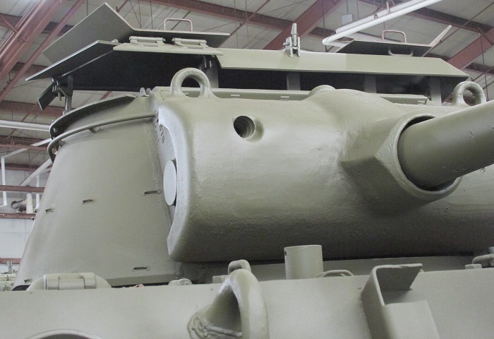
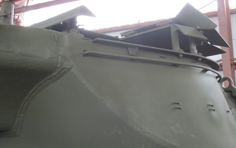
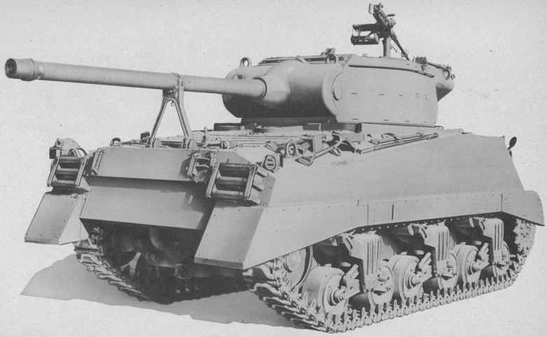
A frontal view of the gun shield is provided here; note that the turret on this vehicle is pointed to the rear. This carriage has been fitted with the folding armored roof, the outboard doors of which are open.
The aperture for the gunner's M76D telescope was stepped.
A side view of the armored roof kit is provided here. Three doors could be folded forward to provide unfettered access, and the kit itself allowed a small distance from the turret top to retain all-round vision. Bosses for applique armor are present on the hull, but the 90mm gun turret was not similarly outfitted.
Further details of the roof kit are provided here. The middle door remains latched, while the two outer doors are folded forward. The front vision doors are opened upward as well.
The large turret bustle helped to counterbalance the heavy 90mm gun as well as provide an ammunition stowage space. Placement of the .50cal machine gun mount can also be seen.
The exhaust deflector associated with the Ford GAA engine is present on this vehicle, and the later-production 90mm gun travel lock is raised.
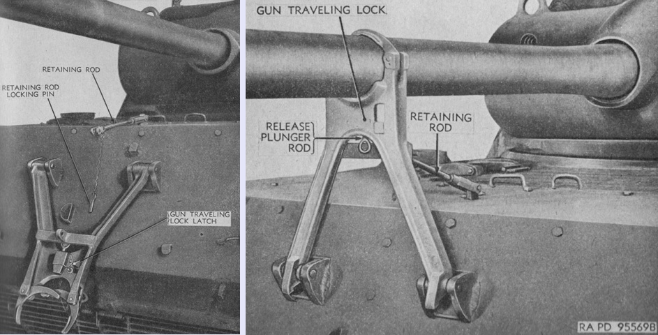
The travel lock is shown here stowed on the left and in use on the right. After the travel lock was unlatched from the hull, it was swung up and secured to the retaining rod by the locking pin chained to the retaining rod, and the gun could then be lowered into the lock. To disengage the travel lock, the release plunger rod was pulled down, and the gun could then be elevated to clear the lock, which was finally swung down and latched to the hull rear. (Picture from TM 9-374 C1 90-mm Guns M3 and M3A1 for Combat Vehicles.)
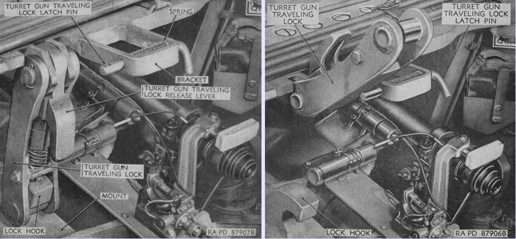
In addition, the gun could be locked for elevation by a traveling lock inside the turret that engaged a hook on the gun mount. The lock is shown engaged on the left, and on the right the lock is stowed and secured by a spring-loaded pin. (Picture from TM 9-374 C1 90-mm Guns M3 and M3A1 for Combat Vehicles.)
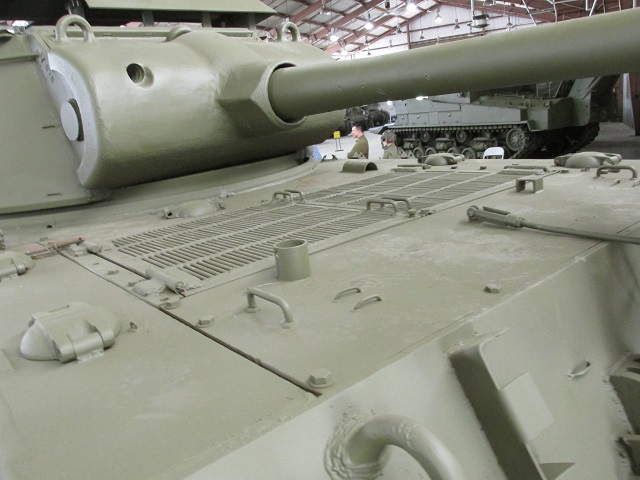
The wide air intake grilles were a hallmark of the GAA engine. The filler cap in the foreground was for the left rear fuel tank, and the one between the turret and the air intake grilles was for the cooling system.
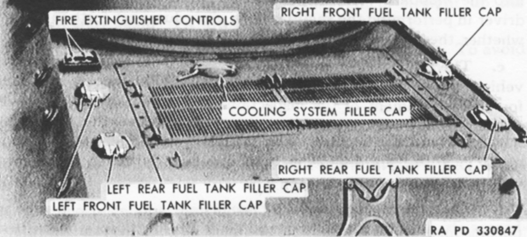
The various filler caps are labeled in this image. (Picture from TM 9-758 90-mm Gun Motor Carriage T71.)
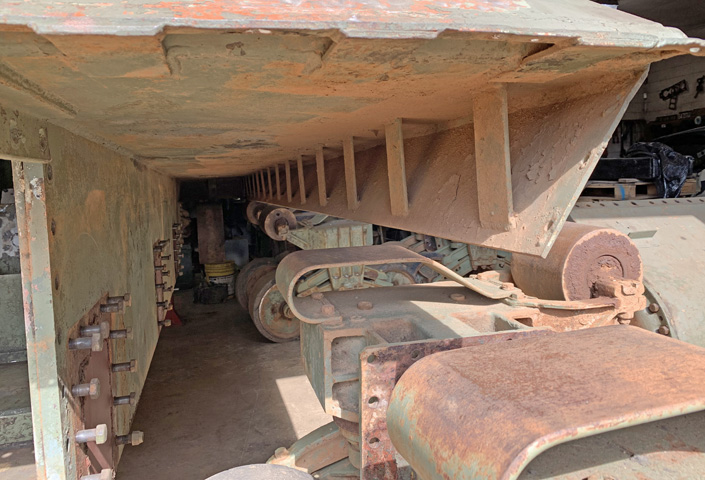
This vehicle is undergoing restoration. With the suspension bogies and final drive and differential cover removed, details of the sponson construction and hull side armor thickness can be seen.
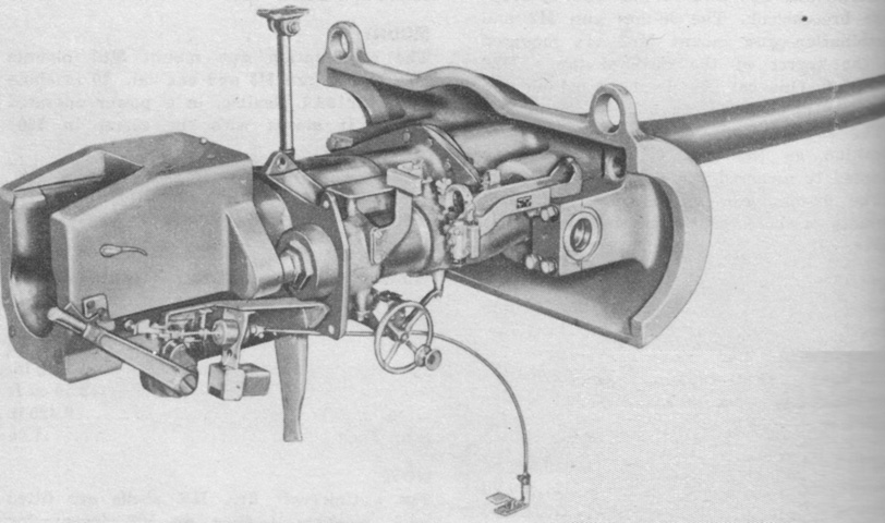
The 90mm gun M3 and mount M4 are seen from the right rear. The mount M4 weighed 1,640lb (743.9kg) without the gun, while the gun's tube and breech mechanism weighed 2,260lb (1,030kg). Normal recoil length for the hydrospring recoil mechanism was 11¾" (29.85cm), with a maximum of 14" (36cm). (Picture from TM 9-2300 Artillery Matériel and Associated Equipment.)
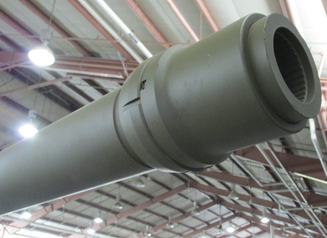
Although threaded for a muzzle brake, one is not mounted on this vehicle. A thread protector is installed instead.
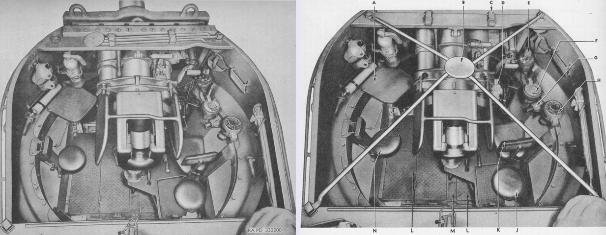
The interior of the turret is shown here. A folding frame for a canvas foul weather cover is stowed above the gun shield on the left, and is erected on the right. A fire extinguisher is mounted on the turret front wall next to the canteens. The loader sat to the left of the gun, while the other two turret crew were positioned to its right. The legend for the right image is: A. Platform, ass'y. B. Support, ass'y. C. Strap. D. Pump, ass'y. E. Motor, ass'y. F. Mechanism, ass'y. G. Lock, ass'y. H. Indicator, ass'y. J. Seat, ass'y. K. Seat, ass'y. L. Floor, ass'y. M. Support, ass'y. N. Seat, ass'y. (Pictures from ORD 8-9 SNL G-210 Field and Base Maintenance Spare Parts and Equipment and List of All Service Parts for Carriage, Motor, 90-mm Gun, M36.)
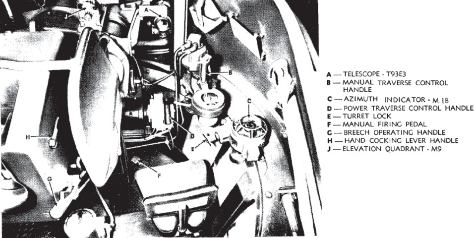
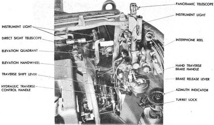
A closer view of the gunner's position is shown in this image. (Picture from TM 9-374 90-mm Gun M3 Mounted in Combat Vehicles.)
The panoramic telescope M12 has been mounted in the telescope mount M69 to the gunner's right front. (Picture from TM 9-374 C1 90-mm Guns M3 and M3A1 for Combat Vehicles.)
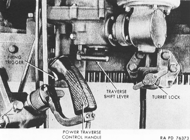
A closeup of the power traverse control handle reveals the firing trigger on its front. The traverse shift lever was moved towards the center of the turret for power operation, or pushed towards the turret wall for manual operation. (Picture from TM 9-758 90-mm Gun Motor Carriage T71.)
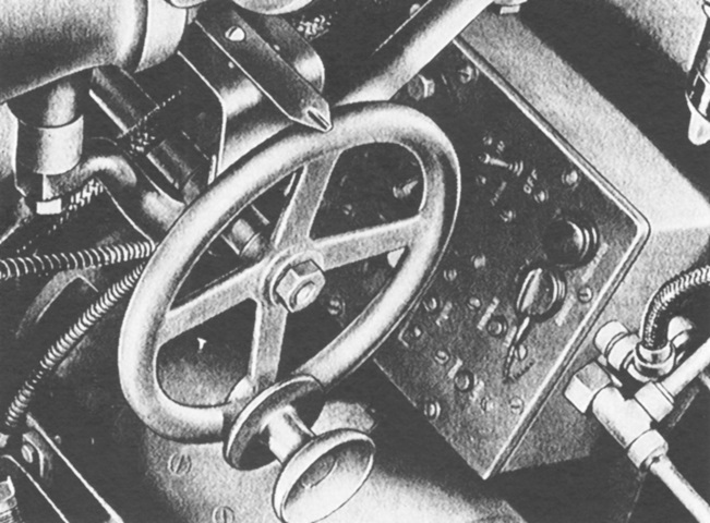
The elevation handwheel was on the right side of the gun mount. The box to the front of the handwheel was for the traversing and firing switches that energized the traversing motor and firing circuits. (Picture from TM 9-758 90-mm Gun Motor Carriage T71.)
The drivers' compartment appeared sparse on the assistant driver's side, since he lacked both driving controls and the machine gun found in tank hulls. (Picture from TM 9-758 90-mm Gun Motor Carriage T71.)
The engine compartment is seen here from above. (Picture from TM 9-758 90-mm Gun Motor Carriage T71.)
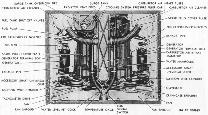
A view into the open rear engine access doors is provided in this image. (Picture from TM 9-758 90-mm Gun Motor Carriage T71.)
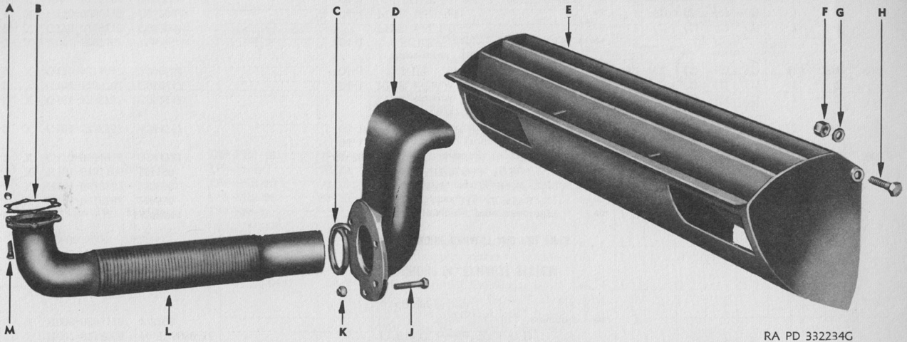
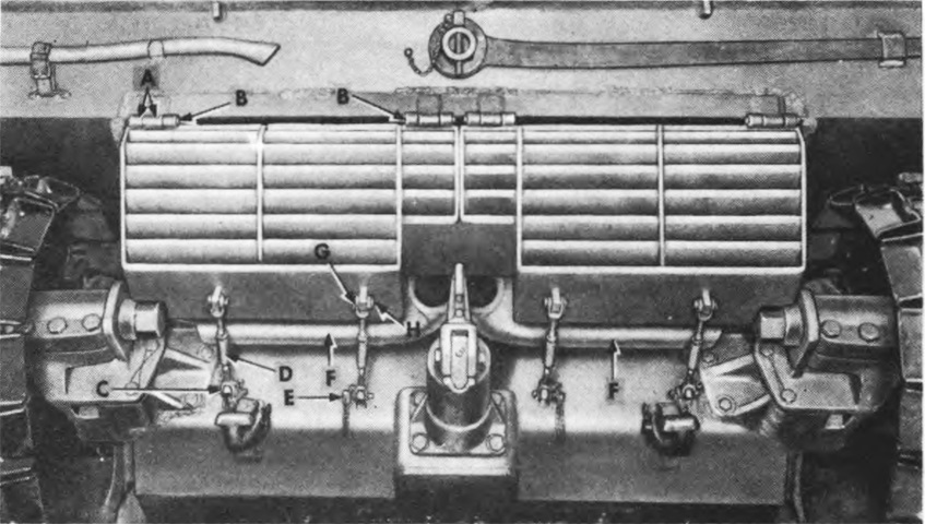
The assembly of an engine exhaust pipe and the exhaust deflector can be gleaned from this image. A. Nut. B. Gasket. C. Packing. D. Pipe. E. Deflector. F. Nut. G. Washer. H. Bolt. J. Bolt. K. Nut. L. Pipe. M. Screw. (Pictures from ORD 8-9 SNL G-210 Field and Base Maintenance Spare Parts and Equipment and List of All Service Parts for Carriage, Motor, 90-mm Gun, M36.)
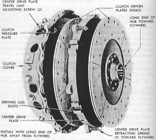
The clutch was a double-plate type similar to the standard automotive variety. The two driven plates had friction facing riveted to each side, and the release fork and release levers were mounted on needle roller bearings. (Picture from TM 9-758 90-mm Gun Motor Carriage T71.)
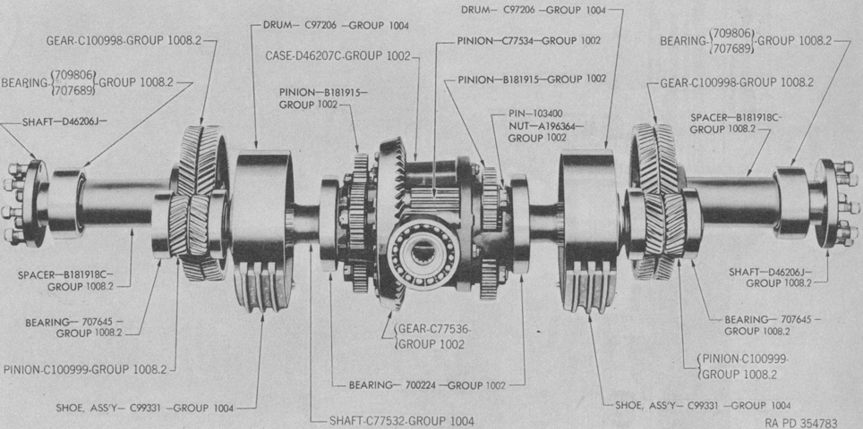
The differential and final drive gears have been assembled in this image. (Pictures from ORD 8-9 SNL G-210 Field and Base Maintenance Spare Parts and Equipment and List of All Service Parts for Carriage, Motor, 90-mm Gun, M36.)
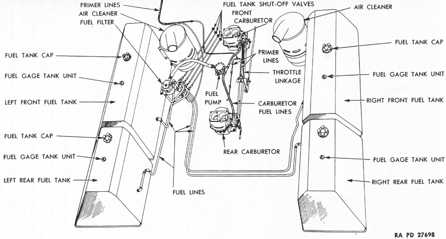
The four fuel tanks were in the engine compartment sponsons. The rear two tanks each held 39.5gal (150L), the front right tank held 58gal (220L), and the front left tank held 55gal (210L). (Picture from TM 9-758 90-mm Gun Motor Carriage T71.)
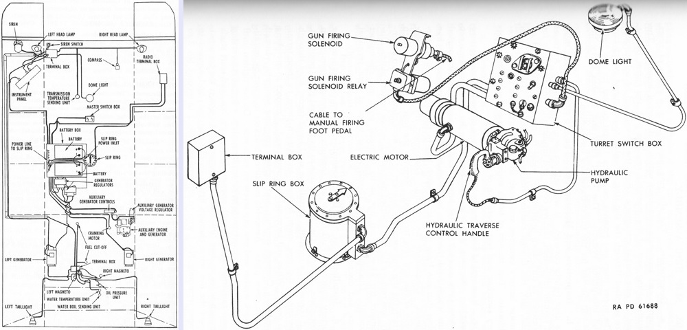
Wiring diagrams for the hull and turret are sketched on the left and right, respectively. Two generators were in the engine compartment, each rated at 30 volts and 50 amperes, with a combined capacity of 1,500 watts. Two 12-volt batteries were connected in series on the left side of the hull. The starting, lighting, turret traverse, turret dome light, and gun firing circuits operated on 24 volts, while the radio and interphone used 12 volts. A slip ring assembly permitted current to be provided to the turret while allowing turret traverse. Note the arrow on top of the slip ring, which the crew could use to determine where the turret was pointed. (Picture from TM 9-758 90-mm Gun Motor Carriage T71.)
The hull of this vehicle is that of the late-production M4A3 with stowage rearranged to accommodate 90mm ammunition; hence, the bow machine gun is present. (Picture from ORD 9 SNL G-233 List of All Service Parts for Carriage, Motor, 90-mm. Gun, M36B1.)
The turret has been traversed to the rear, and the 90mm gun is secured in its travel lock. On the medium tank, the radio was mounted in the turret bulge, but the M36B1 necessarily retained the M36's radio position adjacent to the assistant driver. An antenna mast was routed to the exterior above the right fender. (Picture from ORD 9 SNL G-233 List of All Service Parts for Carriage, Motor, 90-mm. Gun, M36B1.)
The travel lock was relocated from the hull rear plate to the hull roof. Track blocks are stowed above the rear fenders, and a folding blanket rack for the crew is attached to the rear hull plate. (Picture from ORD 9 SNL G-233 List of All Service Parts for Carriage, Motor, 90-mm. Gun, M36B1.)
The open-topped turret is showcased from this angle. The length of the turret bustle is better illustrated, and the .50cal machine gun is stowed on the rear of the bustle. A spare .50cal barrel is on top of the turret bustle. (Picture from ORD 9 SNL G-233 List of All Service Parts for Carriage, Motor, 90-mm. Gun, M36B1.)
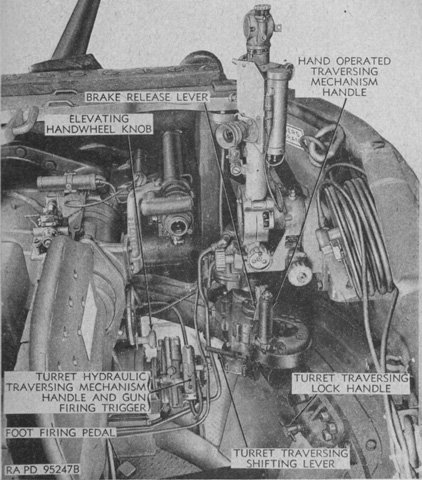
Another view of the turret controls is provided here. (Picture from TM 9-748 90-mm Gun Motor Carriage M36B1.)
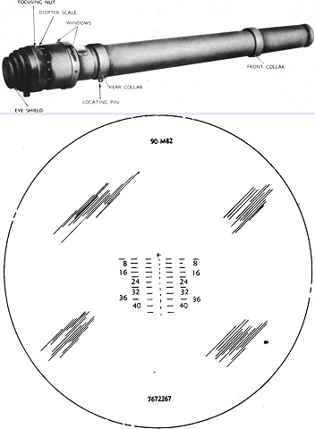
The telescope M76F is seen at the top with its reticle sketched below. It was a 3x instrument with a field of view of 21°30'. (Picture from TM 9-748 90-mm Gun Motor Carriage M36B1.)
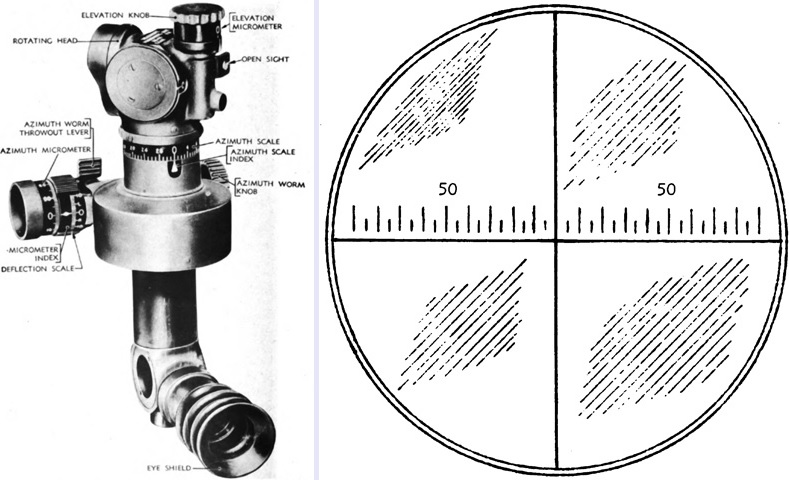
The panoramic telescope M12 was a 4x device with a 10° field of view used to aim the gun in azimuth for indirect fire. The horizontal line of the reticle was graduated in 5-mil intervals up to 100 mils left and right of center. (Picture from TM 9-748 90-mm Gun Motor Carriage M36B1.)
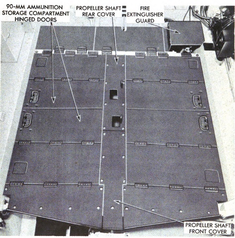
The hull hull floor was made up of the lids of 90mm ammunition boxes. Besides the 11 90mm rounds stowed in the turret bustle, a further 36 were stowed in the hull. (Picture from TM 9-748 90-mm Gun Motor Carriage M36B1.)
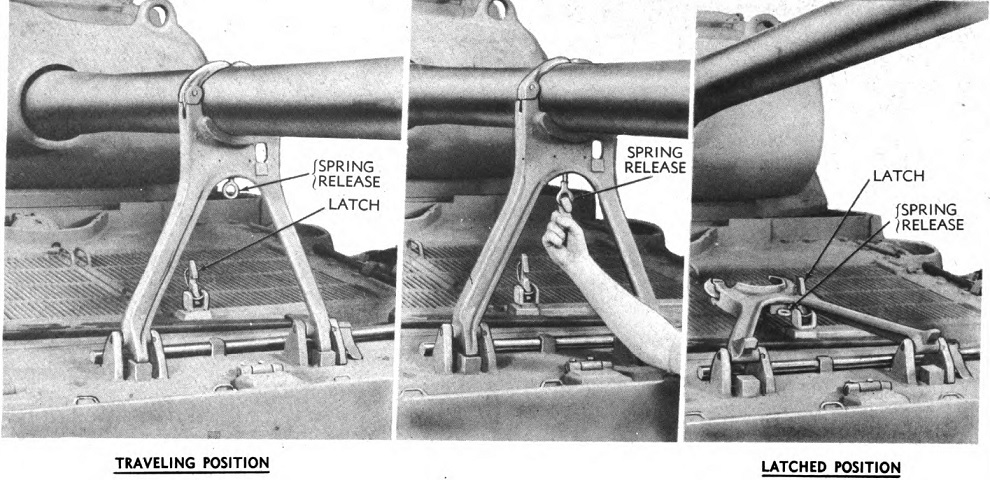
To release the travel lock, the spring release was pulled down and the gun was then elevated. Once free, the travel lock was latched to the rear deck. (Picture from TM 9-748 90-mm Gun Motor Carriage M36B1.)
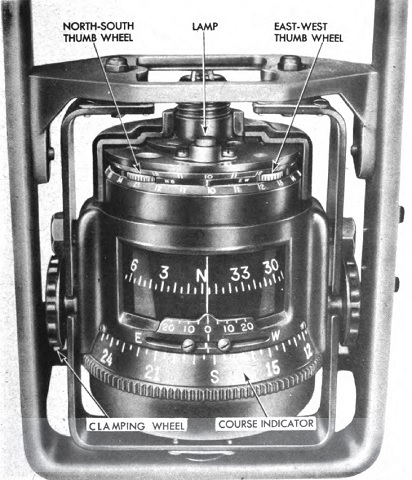
A Sherril AEG-1 compass was mounted above the driver's instrument panel. (Picture from TM 9-748 90-mm Gun Motor Carriage M36B1.)
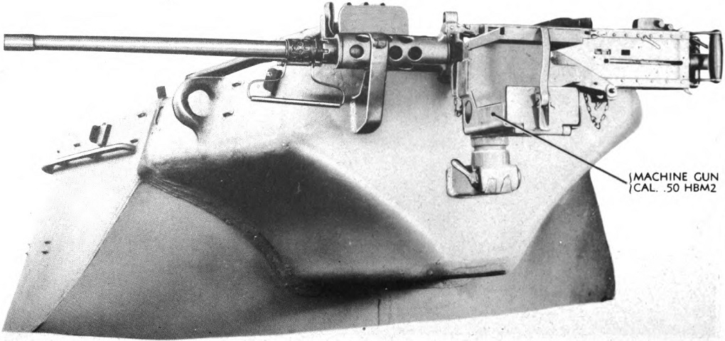
The .50cal machine gun was stowed on the turret rear as shown. (Picture from TM 9-748 90-mm Gun Motor Carriage M36B1.)
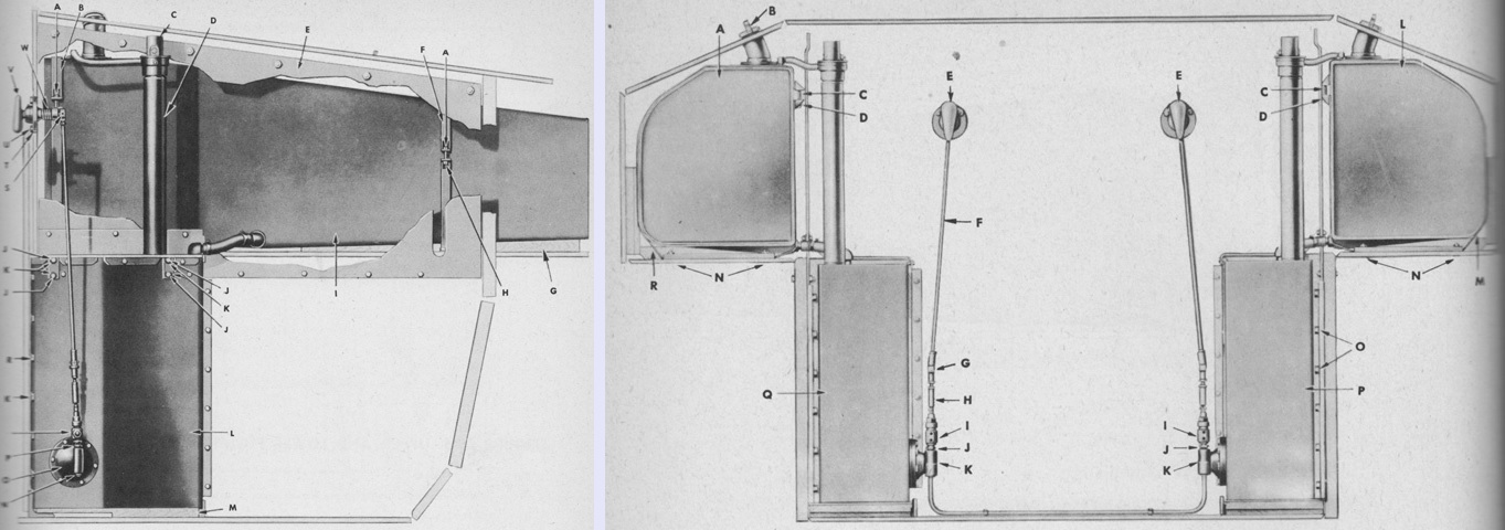
The spatial relationship of the fuel tanks is illustrated in these images; the right-side fuel tanks are on the left, and all four fuel tanks are viewed from the front on the right. The key for the left image is: A. Bolt. B. Strap, assembly. C. Unit, assembly. D. Standpipe, assembly. E. Plate, assembly. F. Strap, assembly. G. Spacer. H. Nut. I. Tank, assembly. J. Screw. K. Washer. L. Tank, assembly. M. Spacer. N. Plug. O. Filter, assembly. P. Nipple. Q. Valve. R. Screw. S. Joint. T. Washer. U. Screw. V. Handle, assembly. W. Spring.
The key for the right image is: A. Tank, assembly. B. Cap. C. Bolt. D. Nut. E. Handle, assembly. F. Rod. G. Clevis. H. Overload, assembly. I. Valve. J. Nipple. K. Filter, assembly. L. Tank, assembly. M. Strap, assembly. N. Bolt. O. Screw. P. Tank, assembly. Q. Tank, assembly. R. Strap, assembly. (Pictures from ORD 9 SNL G-233 List of All Service Parts for Carriage, Motor, 90-mm. Gun, M36B1.)
From this angle, it would be very difficult to differentiate this M36B2 from an M36. This vehicle is fitted with the folding turret roof armor which provided overhead protection while still allowing all-around vision. This vehicle has a muzzle brake, and the .50cal MG is stowed on the turret rear. In addition, it has been modified with the spaced-out suspension that allowed extended end connectors to also be mounted on the inner track run. (Picture from TM 9-745 90-mm Gun Motor Carriage M36B2.)
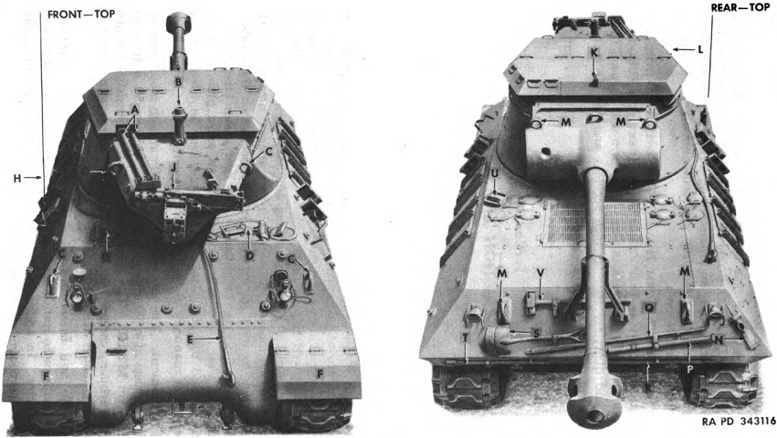
The turret is still reversed, and the image on the right allows us to positively identify the diesel engine deck with its characteristic smaller air inlet grilles and filler cap configuration. The legend is as follows: A. Spare machine gun barrels. B. Machine gun pedestal. C. Lifting eyes. D. Driver's door. E. Towing cable. F. Fenders. G. Assistant driver's door. H. Antenna. J. Machine gun. K. Turret doors' latch. L. Turret top. M. Lifting eyes. N. Pick mattock. P. Pick mattock handle. Q. Crow bar. R. Track adjusting wrench. S. Shovel. T. Ax. U. Exterior fire extinguisher pull handles. V. Sledge. (Picture from TM 9-745 90-mm Gun Motor Carriage M36B2.)
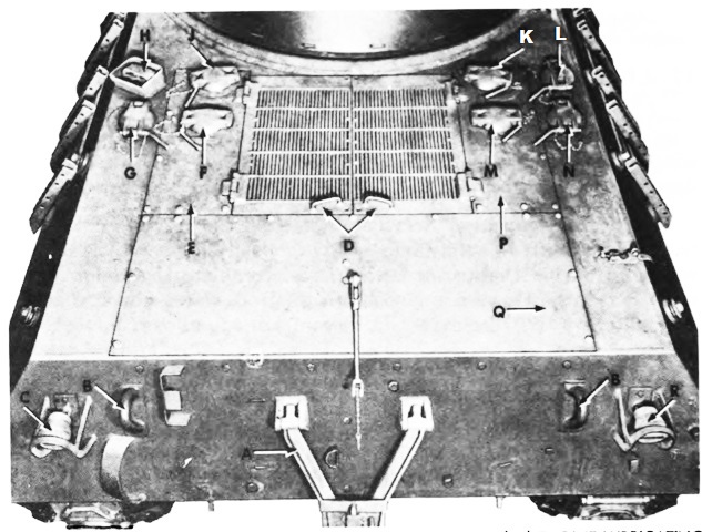
This is a closer view of the engine deck. A. Gun traveling lock. B. Lifting hooks. C. Left taillight. D. Engine compartment doors. E. Engine compartment left cover plate. F. Left water expansion tank filler cover. G. Left fuel tank filler cap cover. H. Fire extinguisher exterior pull handles. J. Left (LC) engine lubricating oil tank filler cap cover. K. Right (LA) engine lubricating oil tank filler cap cover. L. Auxiliary generator fuel tank filler cap cover. M. Right water expansion tank filler cap cover. N. Right fuel tank filler cap cover. P. Engine compartment right cover plate. Q. Engine compartment rear cover plate. R. Right taillight. (Picture from TM 9-745 90-mm Gun Motor Carriage M36B2.)
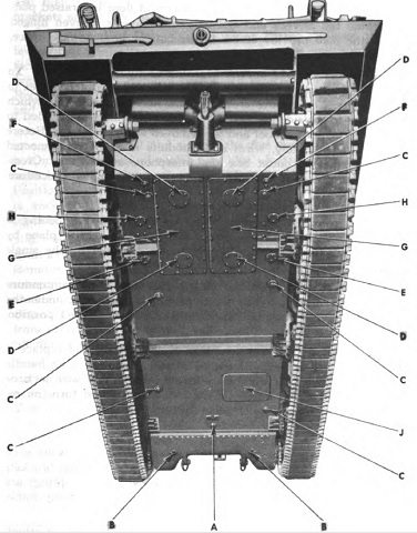
The underside of the hull is illustrated here. A. Transmission drain plug. B. Differential drain plugs. C. Hull drain valves. D. Crankcase drain cover plates. E. Lubricating oil tank drain cover plates. F. Water drain plugs. G. Engine compartment floor plates. H. Lower fuel tank drain cover plates. J. Escape hatch. (Picture from TM 9-745 90-mm Gun Motor Carriage M36B2.)
A two-part exhaust deflector was installed. It was hinged at the top so that it could be swung up and attached to the hull rear to enable access to be gained to the mufflers and supports. A. Hinge. B. Hinge pin. C. Anchor rod boss lowered position. D. Anchor rod. E. Anchor rod locking pin. F. Muffler and support. G. Cotter pin. H. Anchor rod pin. (Picture from TM 9-745 90-mm Gun Motor Carriage M36B2.)
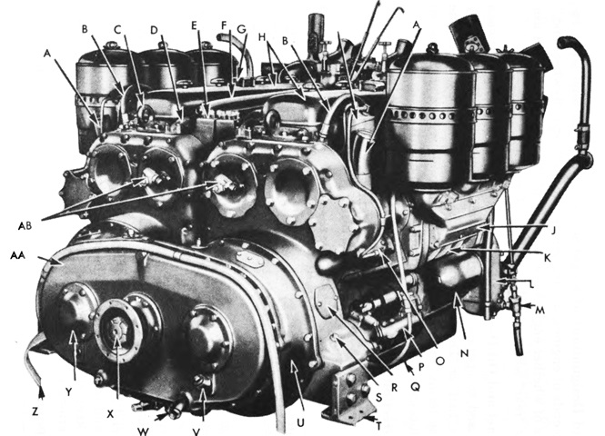
The flywheel end of the twinned engines are shown in this picture. As seen here, the generators previously found on each engine were eventually deleted. A. Oil filler tube. B. Fuel return hose. C. Engine lifting bracket. D. Cylinder head vent. E. Junction plate. F. Water outlet manifold. G. Rocker arm cover breather elbow. H. Rocker arm cover. I. Engine fuel filter. J. Air intake housing. K. Blower. L. Oil cooler. M. Water drain valve. N. Oil strainer. O. Fuel pump. P. Starter. Q. Oil pan. R. Flywheel housing inspection hole cover. S. Starter oil cover plug. T. Rear support bracket. U. Clutch housing. V. Transfer gear housing filter plug. W. Transfer gear housing drain plug. X. Engine driven gear shaft. Y. Engine drive shaft cover. Z. Engine ground strap. AA. Transfer gear housing. AB. Tachometer drive adapters. (Picture from TM 9-745 90-mm Gun Motor Carriage M36B2.)
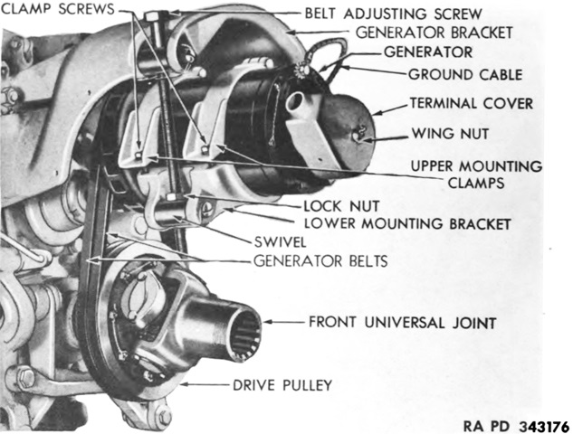
Instead of each engine having a generator, a single 24-volt, 50-ampere generator was mounted on a bracket on the rear of the transmission and driven via a belt by the propeller shaft. (Picture from TM 9-745 90-mm Gun Motor Carriage M36B2.)
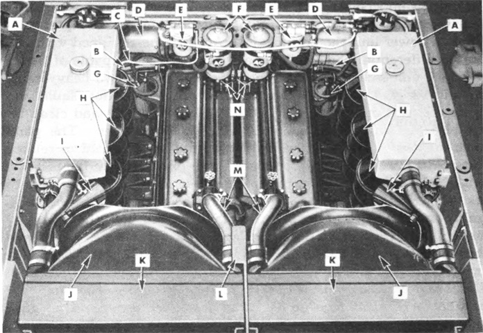
Both dry and wet sump power units were installed, and a dry sump is illustrated here. Each engine in the dry sump unit had an independent pressure-type lubrication system. The oil supply was contained in separate oil supply tanks mounted in the engine compartment next to the lower fuel tanks.
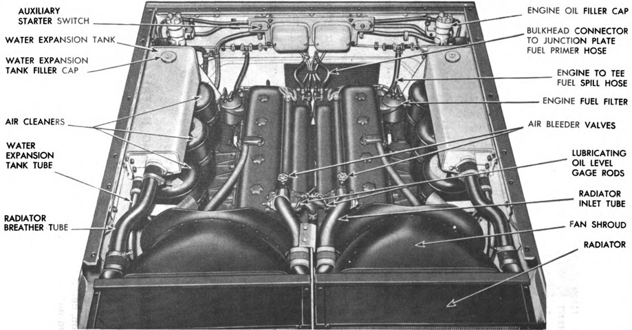
A. Auxiliary water tank. B. Flywheel housing breather hose. C. Air heater pump intake tube. D. Air heater coil box. E. Primary fuel filter. F. Lubricating oil filter. G. Secondary fuel filter. H. Air cleaners. I. Fire extinguisher nozzle. J. Fan shroud. K. Radiator. L. Support plate. M. Radiator inlet tubes. N. Upper junction plates. (Picture from TM 9-745 90-mm Gun Motor Carriage M36B2.)
In the wet sump unit, the oil supply was carried in the crankcase similarly to conventional automobile engines, and was pumped from there to various moving parts. (Picture from TM 9-745 90-mm Gun Motor Carriage M36B2.)
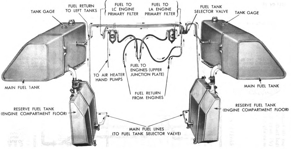
Fuel supply units for a dry sump power unit are shown here. (Picture from TM 9-745 90-mm Gun Motor Carriage M36B2.)
A schematic of the transfer gear unit is provided here. Each engine flywheel drove a dry disk clutch, the driven plates of which were splined to drive shafts that carried helical gears driving the center driven gear on the engine drive shaft. The drive gears had 85 teeth and the driven gear 62, yielding the 1.37x speed increase of the driveshaft compared to the engines' speed.
A. Flywheel housing. B. Flywheel. C. Large oil slinger. D. Clutch spring. E. Release bearing cover. F. Small oil slinger. G. Pilot bearing baffle. H. Engine drive shaft. I. Crankshaft. J. Driven disk hub. K. Release bearing sleeve guide. L. Clutch spring hub. M. Release bearing sleeve. N. Clutch release yoke. O. Clutch driven disk. P. Clutch pressure plate. Q. Clutch cover plate. R. Release shaft. S. Engine drive gear. T. Engine driven shaft. U. Driven shaft flange. V. Engine driven gear. W. Transfer gear housing. X. Clutch housing. (Picture from TM 9-745 90-mm Gun Motor Carriage M36B2.)
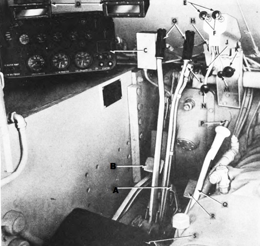
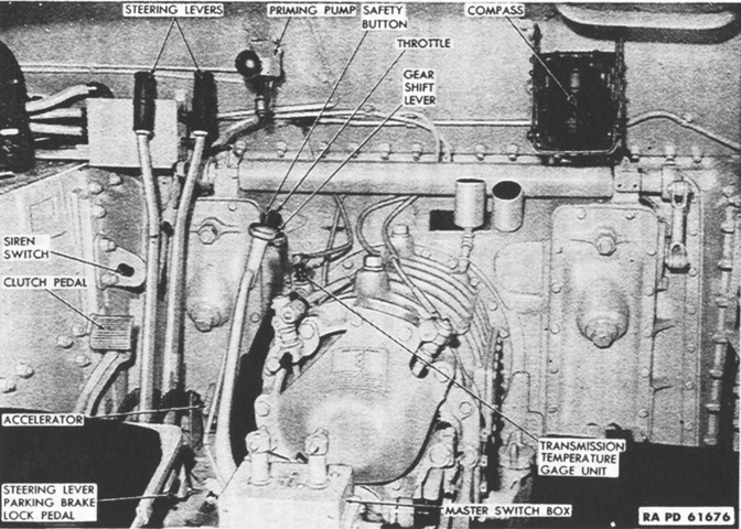
The driver's position is labeled in this picture. A. Parking brake lever. B. Clutch pedal. C. Instrument panel. D. Driver's periscope. E. Clutch lock-out buttons. F. Release buttons. G. Steering levers. H. Air heater pump shut-off valve. J. Left (LC) engine air heater pump. K. Right (LA) engine air heater pump. L. Horn switch. M. Throttle lock lever. N. Throttle. P. Gearshift lever button. Q. Gearshift lever. R. Accelerator pedal. S. Driver's seat. (Picture from TM 9-745 90-mm Gun Motor Carriage M36B2.)
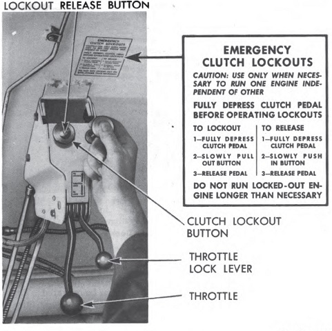
The clutch lockout controls were peculiar to vehicles powered by the twin GM diesels. The lockouts held either or both engine clutches in the disengaged position so one or both engines could be started or used independently or disconnected from the propeller shaft without the driver keeping the clutch pedal pressed. The throttle lever was used to provide sufficient fuel to start and idle the engines, to control the engine speed when the vehicle was stationary, and when moved to the "NO-FUEL" position to stop fuel flow and therefore stop the engines. The throttle lock lever locked the throttle lever in whatever position it occupied. (Picture from TM 9-745 90-mm Gun Motor Carriage M36B2.)
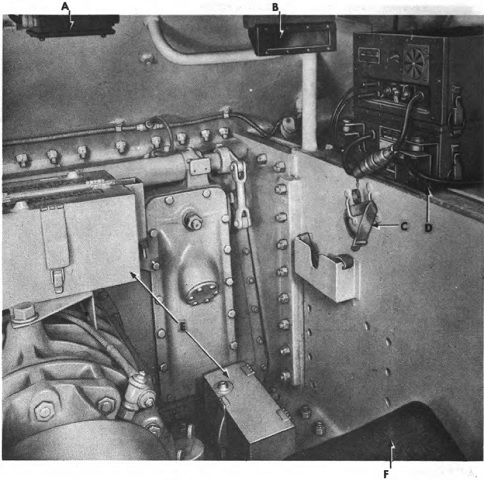
The assistant driver's station is highlighted in this image. A. Hull radio terminal box. B. Assistant driver's periscope. C. Cal. .30 rifle stowage strap. D. Radio set. E. Periscope spare heads stowage box. F. Assistant driver's seat. (Picture from TM 9-745 90-mm Gun Motor Carriage M36B2.)
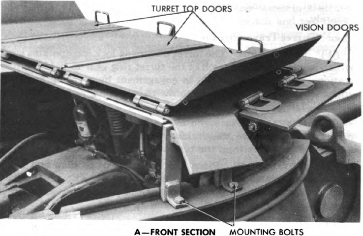
The armored turret top consisted of a front section with hinged turret top doors and vision doors, and a rear shield. The vision doors were equipped with an angular adjustment to balance the need for vision and protection. (Picture from TM 9-745 90-mm Gun Motor Carriage M36B2.)
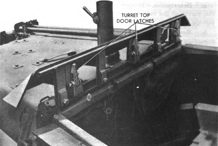
The rear shield mounted the latches for the turret top doors on the front section. (Picture from TM 9-745 90-mm Gun Motor Carriage M36B2.)
