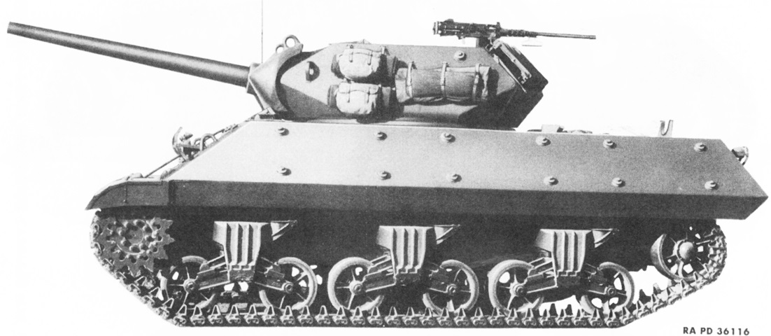
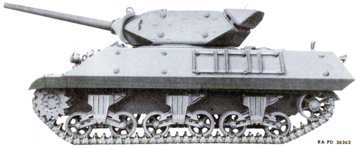
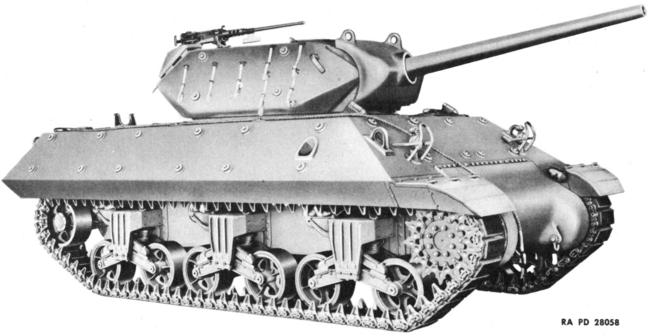
3" Gun Motor Carriage M10.
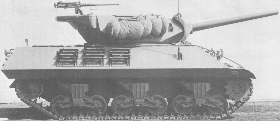
This early-production carriage lacks the rear turret counterweights, instead using that space for stowing track grousers. Bosses for mounting auxiliary armor line the hull and turret sides. (Picture from SNL G-130 Service Parts Catalog for Carriage, Motor, 3-inch Gun, M10.)
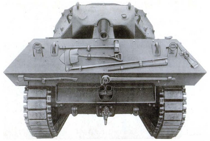
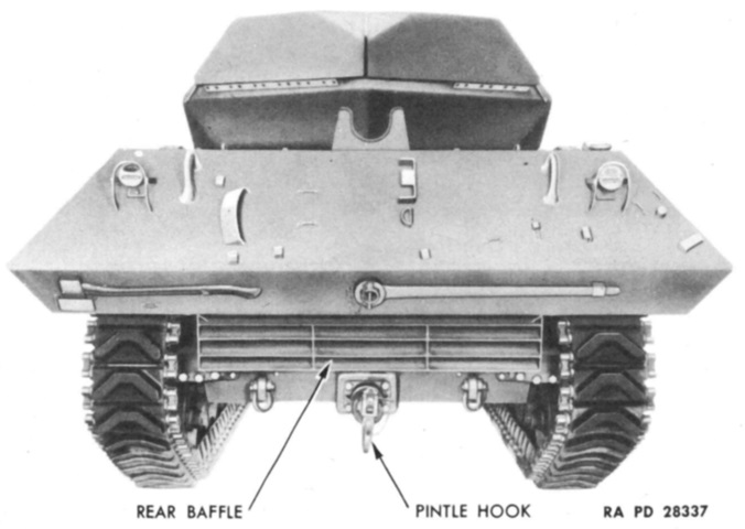
This rear view shows tool stowage on the rear plate as well as the shape of the exhaust baffle. The gun is in its rest on the rear of the top deck, and the tow pintle can be seen below the two engine exhaust outlets. (Picture from TM 9-752 3-inch Gun Motor Carriage M10.)
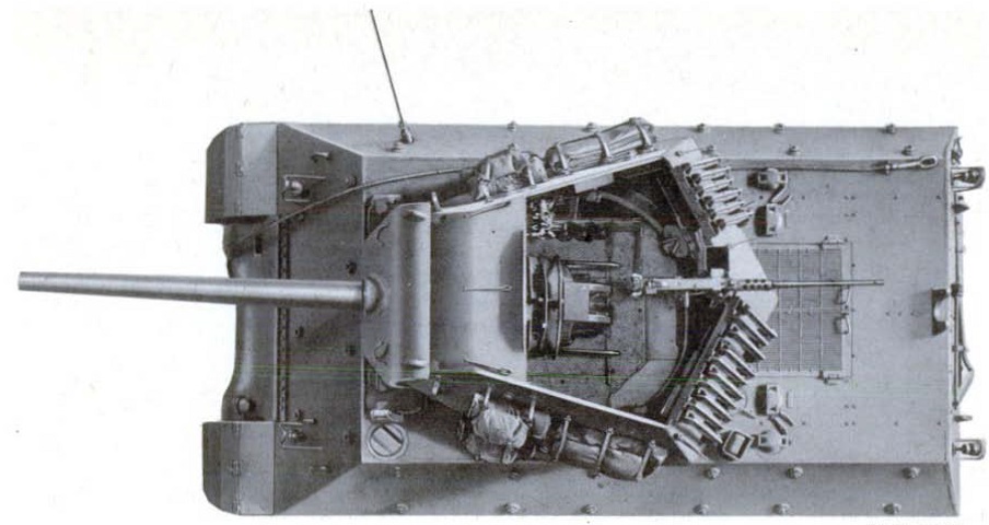
This overhead view allows us to see the partial roof provided to the turret crew. An antenna is present in the mount on the hull right. (Picture from TM 9-752 3-inch Gun Motor Carriage M10.)
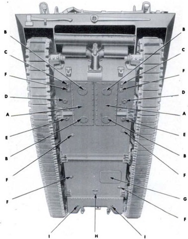
The hull underside is labeled in this picture. A. Engine compartment floor plates. B. Crankcase drain cover plates. C. Water drain plugs. D. Lower fuel tank drain cover plates. E. Lubricating oil tank drain cover plates. F. Hull drain valves. G. Escape hatch. H. Transmission drain plug. I. Differential drain plugs. (Picture from TM 9-752 3-inch Gun Motor Carriage M10.)
Looking under the left sponson from the rear, the supports welded to the bottom of the sponsons and to the inward sloping side armor can be seen in this image. The upper track run is at the right.
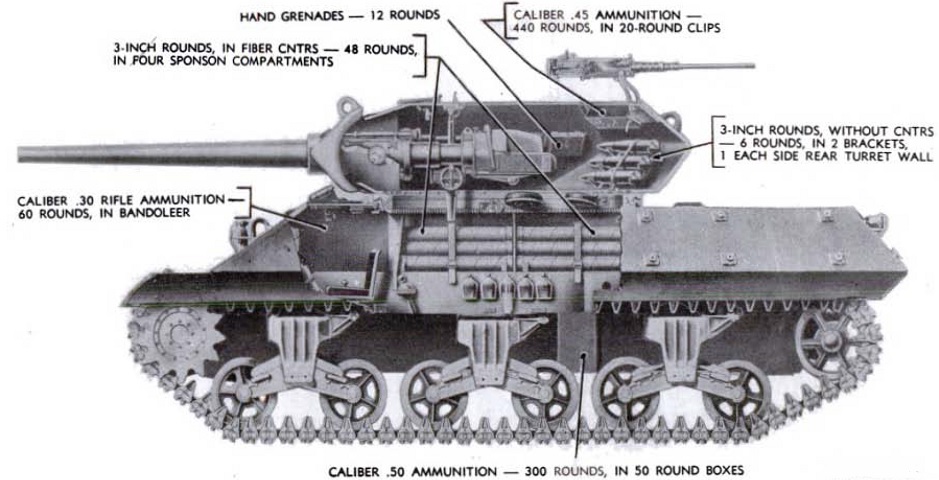
Details of ammunition stowage are diagrammed here. Typically, the 3" ammunition mix was 75% armor-piercing and 25% high explosive. (Picture from TM 9-752 3-inch Gun Motor Carriage M10.)
Counterweights have been added to the turret rear, forcing a relocation of the track grousers. Brackets for stowing the track grousers are instead on the hull side, conveniently mounted via the auxiliary armor bosses. (Picture from TM 9-752 3-inch Gun Motor Carriage M10.)
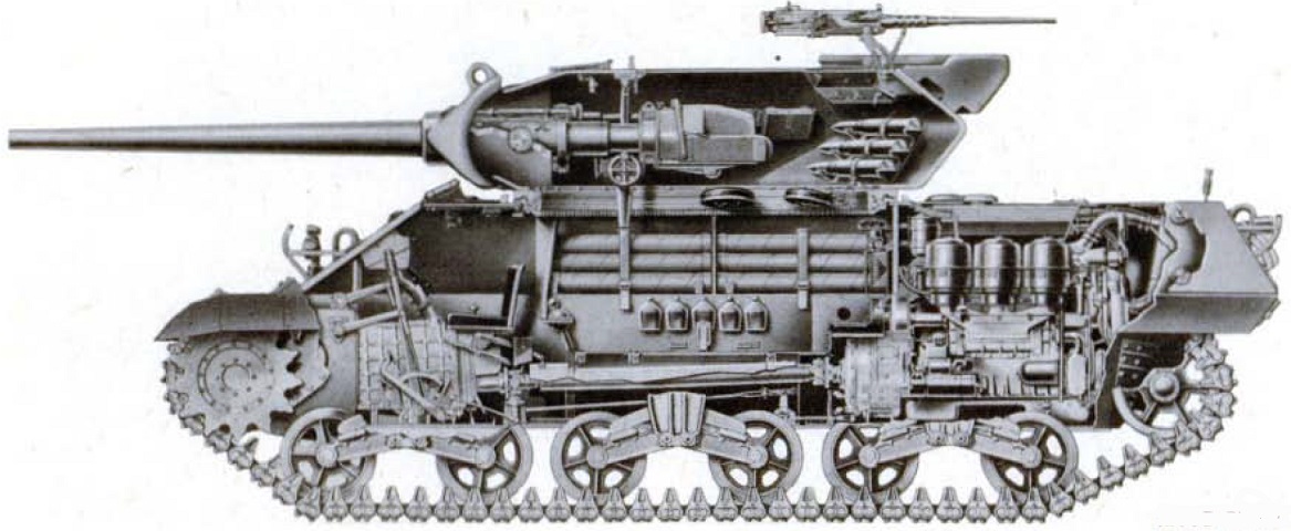
The internal arrangement of the vehicle can be seen in this cross-sectional view. (Picture from TM 9-752 3-inch Gun Motor Carriage M10.)
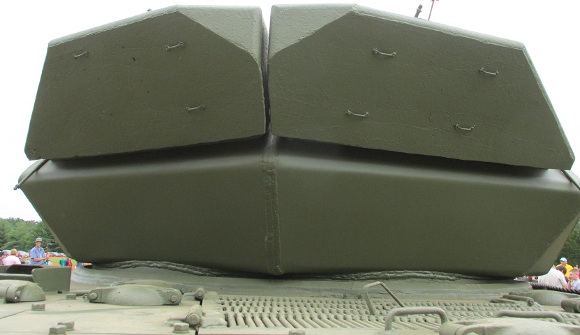
Each counterweight added 1,800lb (820kg) to the back of the turret, easing the manual traverse effort on uneven ground.
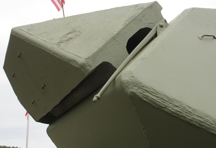
The attachment of the counterweights on the turret rear is highlighted here.
The later duckbill-style counterweights can be seen on this machine. Track grousers are present, and the stowage brackets are mounted directly to the hull after the deletion of the auxiliary armor bosses. (Picture from Tank Data, volume 3.)
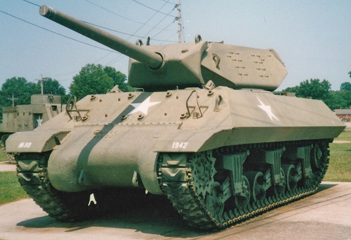
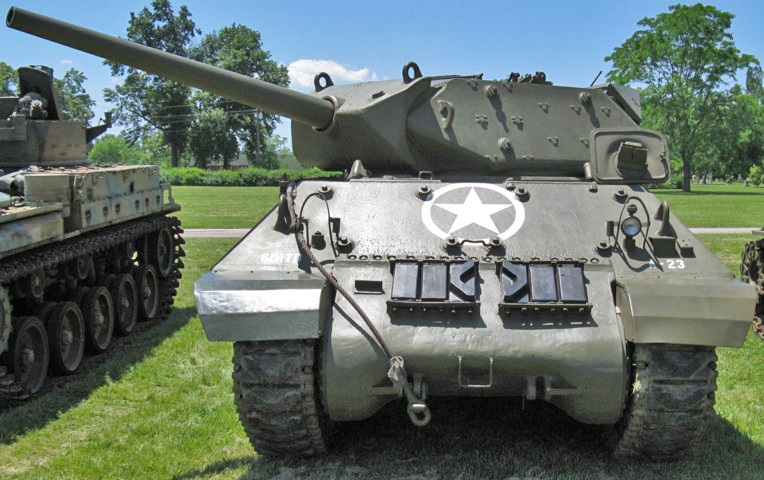
This is a later-production M10, evidenced by the lack of auxiliary armor bosses on the turret and hull sides. Under the sloping hull armor, the M4A2 Sherman origins of the M10 can be made out by focusing on the running gear and lower hull front. The gun shield on the M10 is triangular, compared to the more rounded one on the 90mm GMC M36. This vehicle is sitting on T48 rubber track.
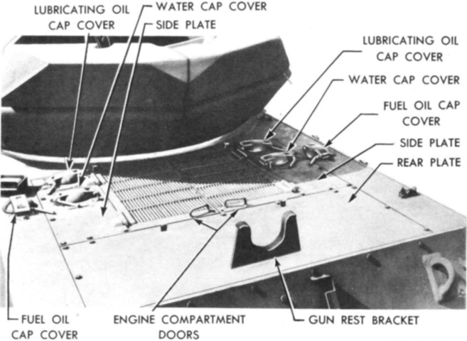
Fixtures on the rear deck of the M10 are labeled in this illustration. (Picture from TM 9-1750L Hull and Turret Electrical Systems, Tracks and Suspension for 3-inch Gun Motor Carriages M10 and M10A1.)
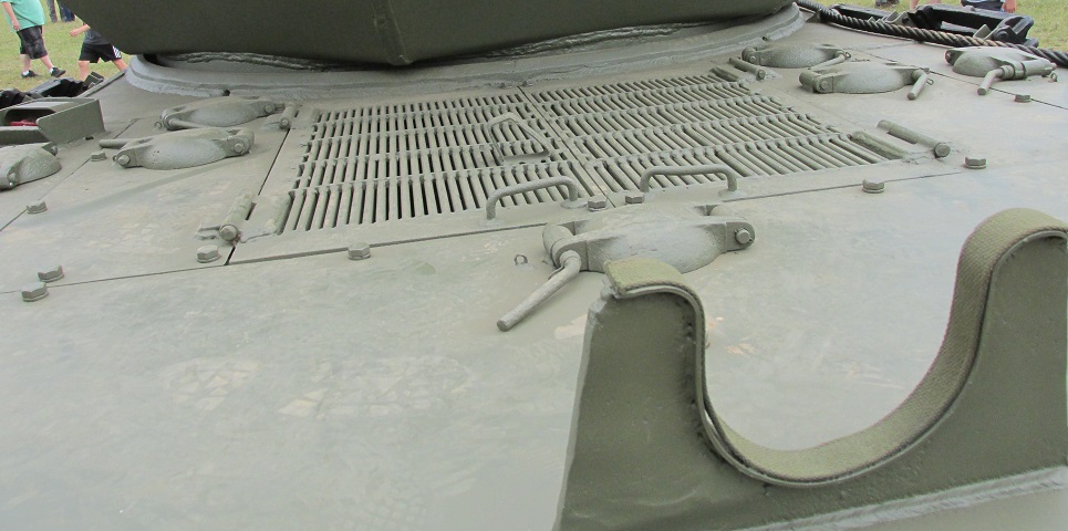
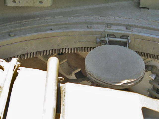
A later version of the engine deck is shown here; note the extra armored cap between the engine grilles and the gun rest bracket in the foreground. Later in production, improvements to the engine lubrication system were introduced that reduced particulate levels and increased cooling. The new cover protected an engine oil gauge added at the same time. The red fire extinguisher controls can be see surrounded by a housing to the upper left of the image.
This is an earlier-production vehicle, as it retains the auxiliary armor bosses on the hull and turret sides. Both T48 and T51 track blocks are stowed on the vehicle's final drive and differential cover.
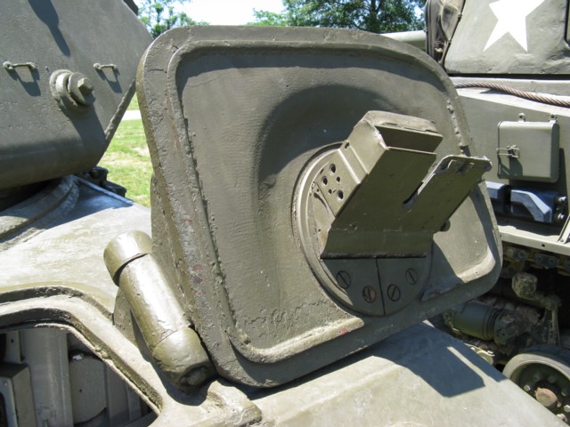
The underside of the driver's hatch is highlighted here. The periscope mount is obvious, but the periscope itself is missing.
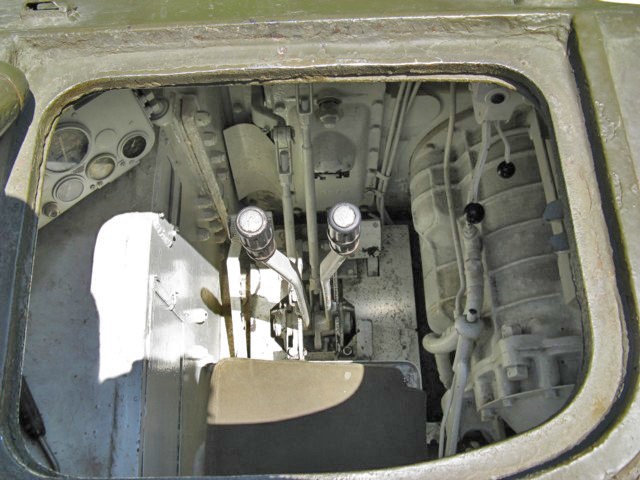
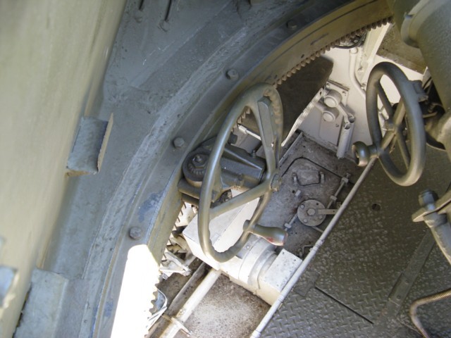
The driver's position is shown here from outside of his hatch. His instrument panel is visible to the left, steering levers are present in front of his seat, and the white gear shift lever is between the seat and the transmission itself to the right.
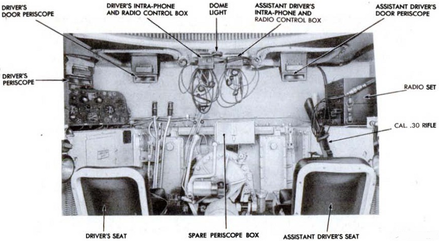
The drivers' compartment is illustrated in this image. (Picture from TM 9-752 3-inch Gun Motor Carriage M10.)
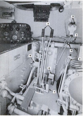
The driver's controls are labeled here. A. Steering levers. B. Clutch lockouts. C. Throttle locking lever. D. Throttle. E. Gearshift lever. F. Brake locking pedal. G. Accelerator pedal. H. Clutch pedal. (Picture from TM 9-752 3-inch Gun Motor Carriage M10.)
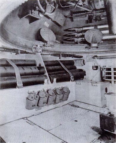
The left side of the fighting compartment is seen here from the front right corner of the hull. Ammunition stowage in the sponson and turret rear can be seen, as well as the traverse handwheel to the right of the image and an elevation handwheel at the top. The vehicle was not equipped with a stowage basket, and the fighting compartment platform left 16" (41cm) of space above the hull floor for stowage. The corner of the driver's seat backrest is in the lower right corner of the image. (Picture from TM 9-752 3-inch Gun Motor Carriage M10.)
The opposite side of the fighting compartment is shown in this image. (Picture from TM 9-752 3-inch Gun Motor Carriage M10.)
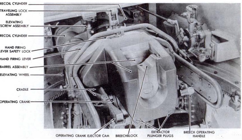
Details of the gun's breech assembly are shown in this picture. Normal recoil distance for its hydrospring recoil system was 11-12" (28-30cm), and maximum recoil was 14" (36cm). (Picture from TM 9-752 3-inch Gun Motor Carriage M10.)
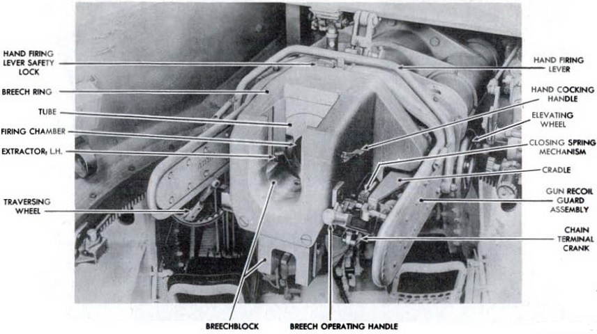
The opposite side of the breech assembly is shown here. An elevation handwheel was available on each side of the weapon. (Picture from TM 9-752 3-inch Gun Motor Carriage M10.)
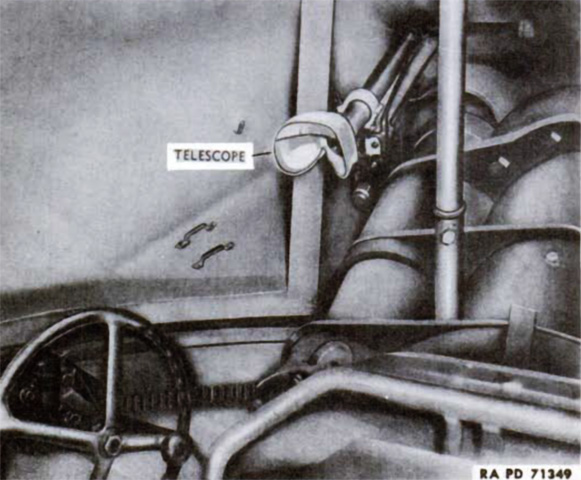
The gunner was provided with a telescope mounted to the left of the gun that elevated and depressed with the gun mount. (Picture from TM 9-752 3-inch Gun Motor Carriage M10.)
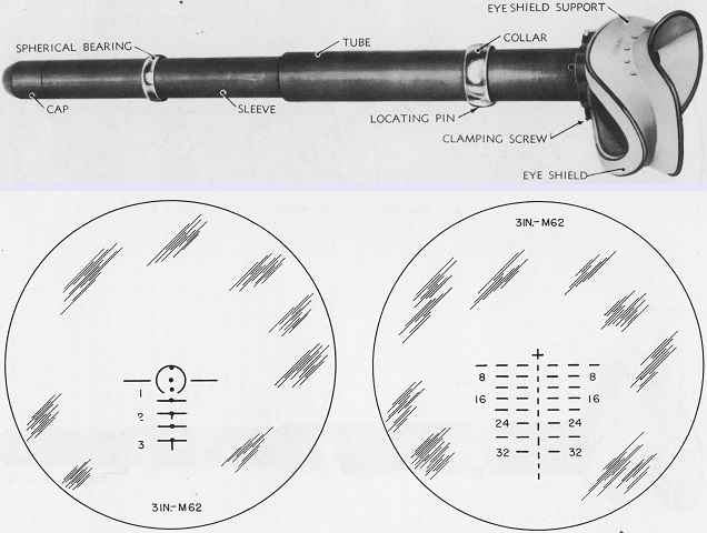
The telescope M51 is seen at the top, and was identical to the telescope M70G except for the reticle. Both were 3x erect image instruments with a 12°19' field of view. The M51's reticle is drawn at the bottom left. The top dot was at the geometric center and represented zero range and deflection. The dot below the top dot represented 600 yards (550m) range, and the arc centered about this dot had a radius of 5 mils. The 10-mil wide lines to each side of the 600 yard dot began 5 mils from the circle and 10 mils from the circle's center. The third dot down was for 1,000 yards (910m) range, and below this were lines representing 1,500, 2,000, 2,500, and 3,000 yards (1,370, 1,830, 2,290, and 2,740m). These lines were 10 mils wide and centered on the center vertical axis of the reticle. Short vertical lines descended from the 2,000 and 3,000 yard lines to assist in centering targets.
The reticle for the telescope M70G is at the bottom right. The center of the upper cross was zero range and deflection, and the horizontal lines and spaces were each 5 mils wide. The broken horizontal lines represented 400-yard (370m) intervals and were numbered in hundreds of yards. Both telescopes were graduated based on the 3" armor-piercing shot M62, as etched in the reticles at the bottom and top, respectively. (Picture from TM 9-323 3-inch Gun M7 Mounted in Combat Vehicles.)
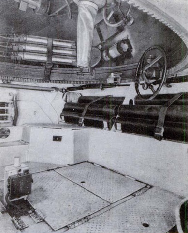
The turret of this vehicle is traversed to the right, and this view is looking through the turret into the hull. The fighting compartment floor is green, while the white hull floor and assistant driver's seat can be seen to the left. The propeller shaft is visible just to the left of the hull floor escape hatch. The handwheel to the left of the image is for turret traverse, and the other is for gun elevation. The electrical firing button can be seen recessed in the elevation handwheel's handle. Each revolution of the elevation handwheel produced a vertical movement of .0833" (.212cm).
The turret crew was provided with folding seats affixed to the turret ring. Stowage for 3" ammunition can be seen in the hull.
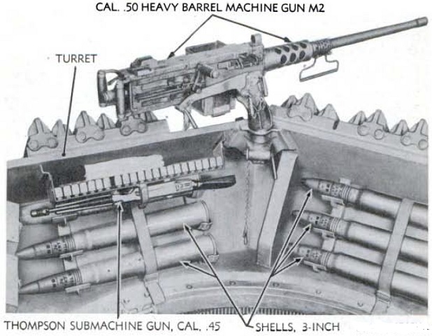
Rear turret stowage of 3" ammunition and a submachine gun is illustrated here. Six 3" rounds, one of which is obscured by the Thompson, were stowed in this area. (Picture from TM 9-752 3-inch Gun Motor Carriage M10.)
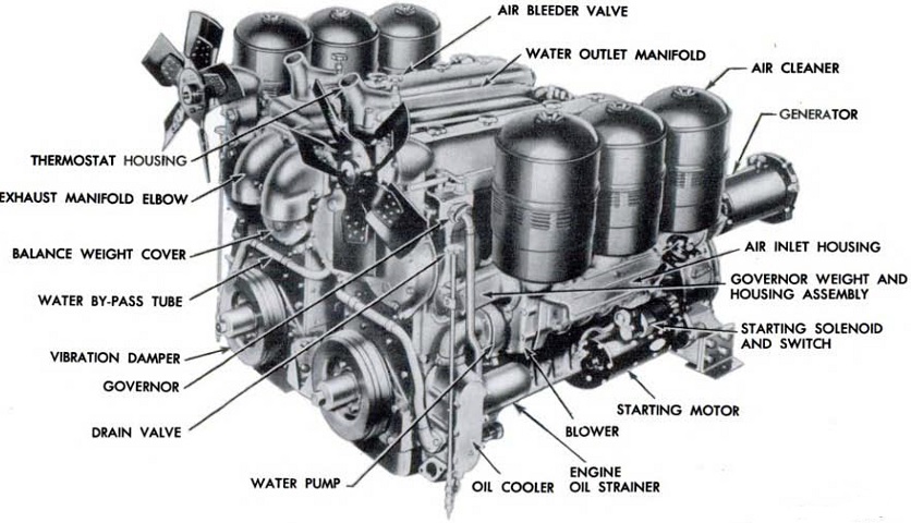
The fan end of the twin diesel engines is shown outside of the engine compartment in this picture. Confusion with the initial engine orientation system was alleviated by using the terms "fan end" or "flywheel end" instead of "front" and "rear;" also, the right and left engines were based on the hull's orientation. The LC engine was the therefore left engine, and the LA engine was the right engine. (Picture from TM 9-752 3-inch Gun Motor Carriage M10.)
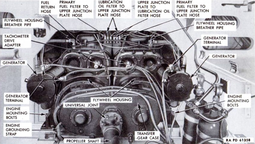
The flywheel end of the power unit is shown here with the bulkhead opening covers removed. (Picture from TM 9-752 3-inch Gun Motor Carriage M10.)
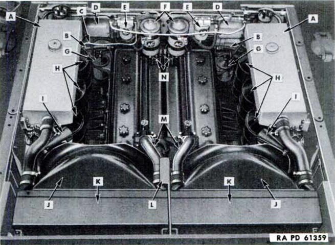
The engine compartment is labeled here with the cover plates removed. A. Auxiliary water tank. B. Flywheel housing breather hose. C. Air heater pump intake tube. D. Air heater coil box. E. Primary fuel filter. F. Lubricating oil filter. G. Secondary fuel filter. H. Air cleaners. I. Fire extinguisher nozzle. J. Fan shroud. K. Radiator. L. Support plate. M. Radiator inlet tubes. N. Upper junction plates. (Picture from TM 9-752 3-inch Gun Motor Carriage M10.)
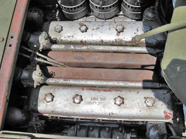
The rear of the vehicle is to the left of this image. The twin GM 6-71 engines that make up the 6046 are visible here. Red paint is fading from the now silver valve rocker covers. The water outlet manifolds are just inboard of the rocker covers, and the exhaust manifolds are in the middle. The black cylindrical air cleaners can be seen to the top of the image. The knobs to the left are for the drain valve and handle assembly.
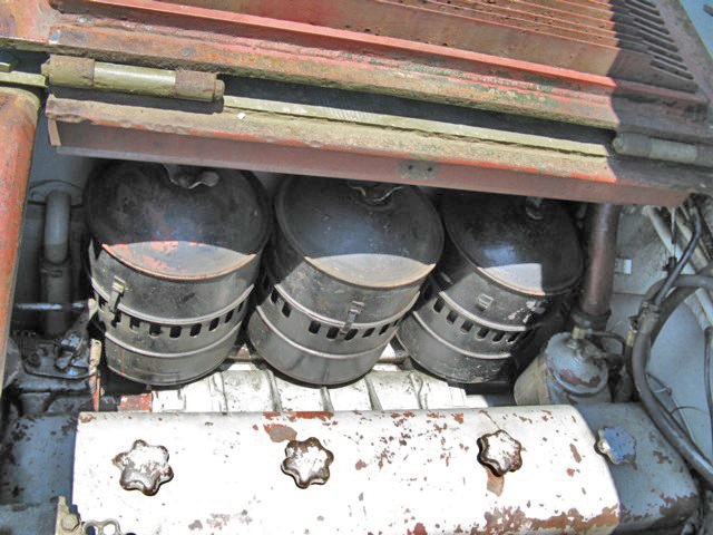
The engine air cleaners can be better seen in this picture. The cylinder to the right of the forward air cleaner is a secondary fuel filter.
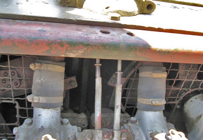
The rear of the engine compartment is shown here. The engine fans are behind their protective mesh shrouds, and the thermostat housings and water outlet tubes are visible in the center of the image. The engine oil gauge added during production can also be seen.
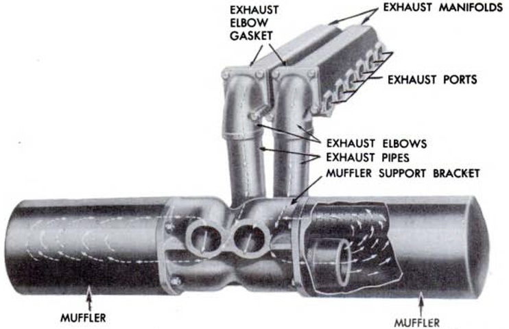
Each engine had its own exhaust manifold, exhaust pipe, and muffler. The exhaust airflow is diagrammed in this picture. (Picture from TM 9-752 3-inch Gun Motor Carriage M10.)
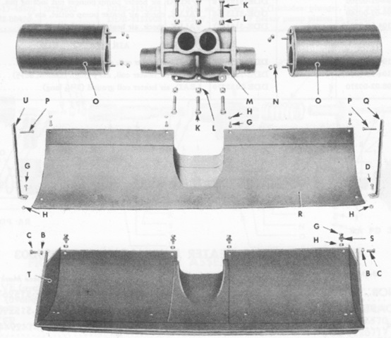
A disassembled view of the muffler and the early and late exhaust deflectors is provided here. B. Washer. C. Screw. D. Screw. G. Screw. H. Nut. K. Bolt. L. Nut. M. Support. N. Nut. O. Muffler. P. Screw. Q. Strap. R. Deflector. S. Washer. T. Deflector. U. Strap. (Picture from SNL G-130 Service Parts Catalog for Carriage, Motor, 3-inch Gun, M10.)
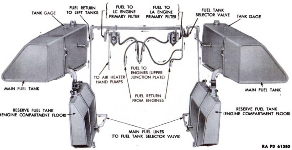
Each main fuel tank held 68gal (260L), and each reserve tank had a capacity of 14.5gal (36.8L). The reserve tanks were connected to the main tanks, and were filled through the main tanks, but only the main tanks were provided with fuel gages. Fuel flowed to the power unit from the lower reserve tank on either side, depending on the fuel tank selector valve setting, and overflow from the injectors was returned to the main tank of the currently-selected pair. (Picture from TM 9-752 3-inch Gun Motor Carriage M10.)
The transmission gearing and shift forks are shown assembled. A. Shaft, ass'y. B. Gear. C. Sleeve. D. Gear. E. Bracket. F. Gear, w Cone and Rollers, ass'y. G. Synchronizer, ass'y. H. Fork. I. Gear, w Cone and Rollers, ass'y. J. Gear, ass'y. K. Gear, ass'y. L. Fork. M. Screw. N. Gear, w Cone and Rollers, ass'y. O. Fork. P. Synchronizer, ass'y. Q. Gear, w Cone and Rollers, ass'y. R. Rod. S. Shaft. T. Rod. U. Rod. (Picture from SNL G-130 Service Parts Catalog for Carriage, Motor, 3-inch Gun, M10.)
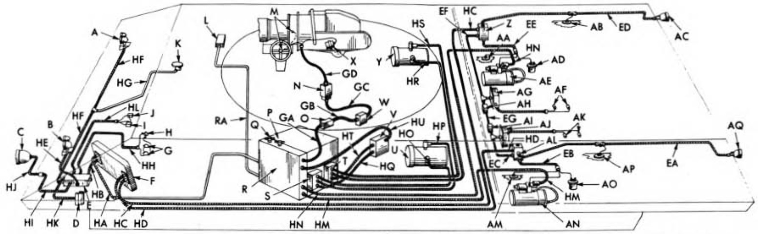
Though using manual traverse and diesel engines, the electrical system was still extensive. Two 12-volt batteries under the left side of the fighting compartment floor were connected in series to form a 24-volt single wire type electrical system. A. Right headlight. B. Left headlight. C. Siren. D. Blackout driving light resistor box. E. Hull terminal box. F. Instrument panel. G. Stoplight switches. H. Siren switch. I. LC oil pressure micro switch. J. LA oil pressure micro switch. K. Domelight. L. Radio terminal box. M. Gun firing switches. N. Turret interphone control box bracket. O. Gun firing circuit breaker box. P. Radio master switch. Q. Battery master switch. R. Battery box. S. LC generator regulator. T. LA generator regulator. U. LC generator. V. Generator radio filter box. X. Gun firing solenoid. Y. LA generator. Z. LA engine terminal box. AA. Right lubricating oil tank gage unit. AB. Right upper fuel tank gage unit. AC. Right taillight. AD. LA emergency stop solenoid. AE. LA starter. AF. LA air heater electrodes. AG. LA air heater ignition coils. AH. LA auxiliary starter switch. AI. LC auxiliary starter switch. AJ. LC air heater ignition coils. AK. LC air heater electrodes. AL. LC engine terminal box. AM. Left lubricating oil tank gage unit. AN. LC starter. AO. LC emergency stop solenoid. AP. Left upper fuel tank gage unit. AQ. Left taillight. (Picture from TM 9-752 3-inch Gun Motor Carriage M10.)
This earlier-production vehicle also has auxiliary armor bosses on the turret and hull sides. There is an indentation for an antenna mount in the hull side. The .50cal machine gun is mounted, and stowage for a towing cable is visible. (Picture from TM 9-1750L Hull and Turret Electrical Systems, Tracks and Suspension for 3-inch Gun Motor Carriages M10 and M10A1.)
The different exhaust baffle for the GAA engine serves to identify this machine as an M10A1. (Picture from TM 9-1750L Hull and Turret Electrical Systems, Tracks and Suspension for 3-inch Gun Motor Carriages M10 and M10A1.)
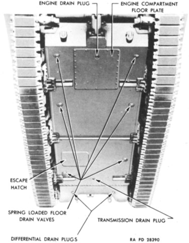
Openings on the hull underside are labeled here. (Picture from TM 9-1750L Hull and Turret Electrical Systems, Tracks and Suspension for 3-inch Gun Motor Carriages M10 and M10A1.)
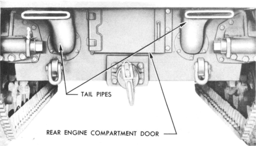
The GAA-type exhaust and engine compartment rear door can be seen in this picture. (Picture from TM 9-1750L Hull and Turret Electrical Systems, Tracks and Suspension for 3-inch Gun Motor Carriages M10 and M10A1.)
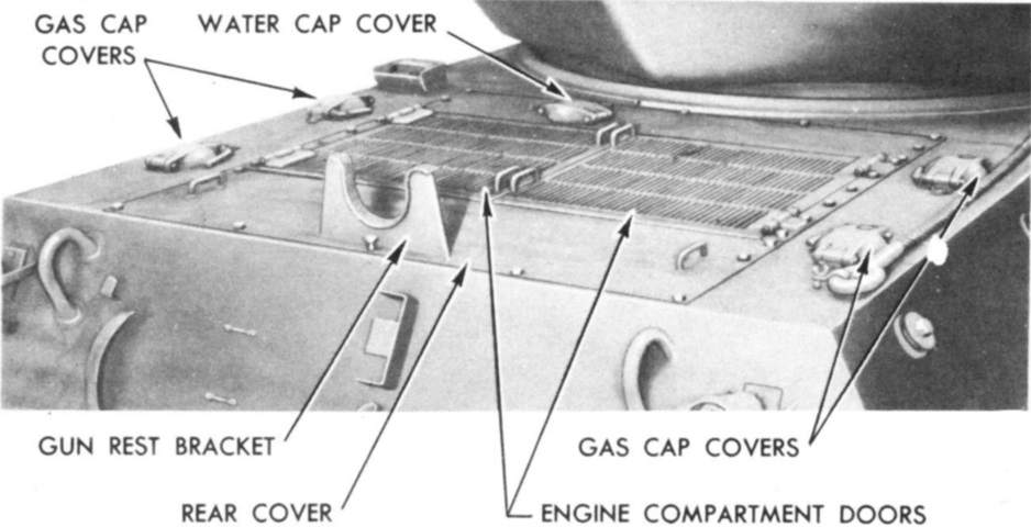
Compared to the rear deck on the M10, that of the M10A1 featured wider air intake grille doors. The different arrangement of the various filler caps and the fire extinguisher handles can also be seen. (Picture from TM 9-1750L Hull and Turret Electrical Systems, Tracks and Suspension for 3-inch Gun Motor Carriages M10 and M10A1.)
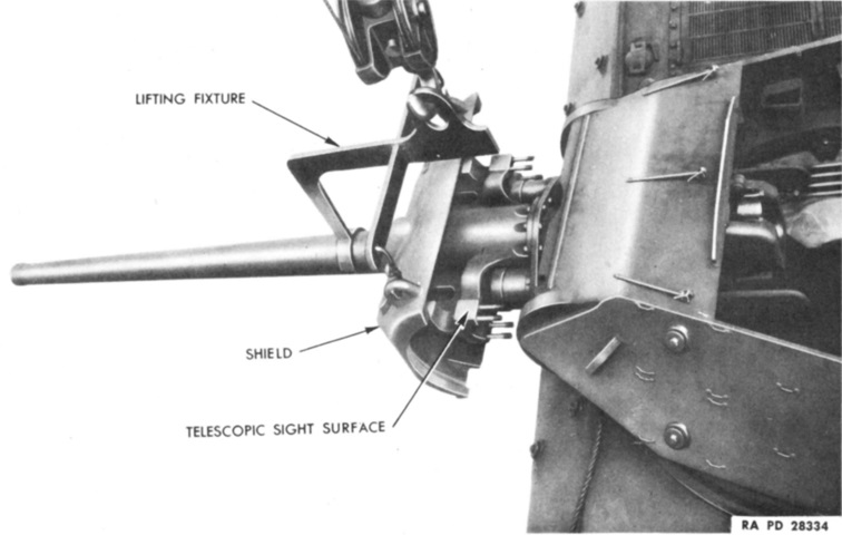
The ordnance and gun mount are shown here in the process of removal. (Picture from TM 9-1750L Hull and Turret Electrical Systems, Tracks and Suspension for 3-inch Gun Motor Carriages M10 and M10A1.)
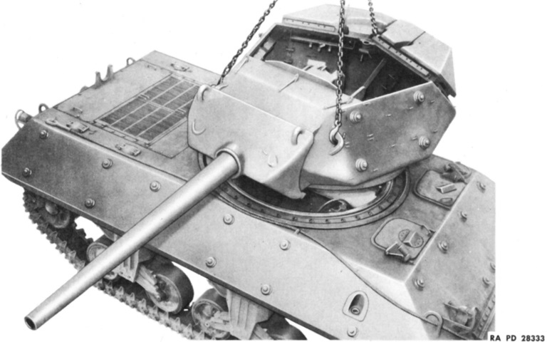
The turret is being removed in this picture. Note the lack of a turret basket. (Picture from TM 9-1750L Hull and Turret Electrical Systems, Tracks and Suspension for 3-inch Gun Motor Carriages M10 and M10A1.)
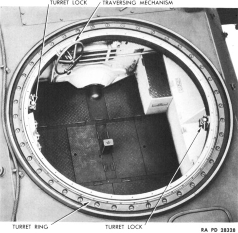
The hull interior with the turret removed is revealed in this image. (Picture from TM 9-1750L Hull and Turret Electrical Systems, Tracks and Suspension for 3-inch Gun Motor Carriages M10 and M10A1.)
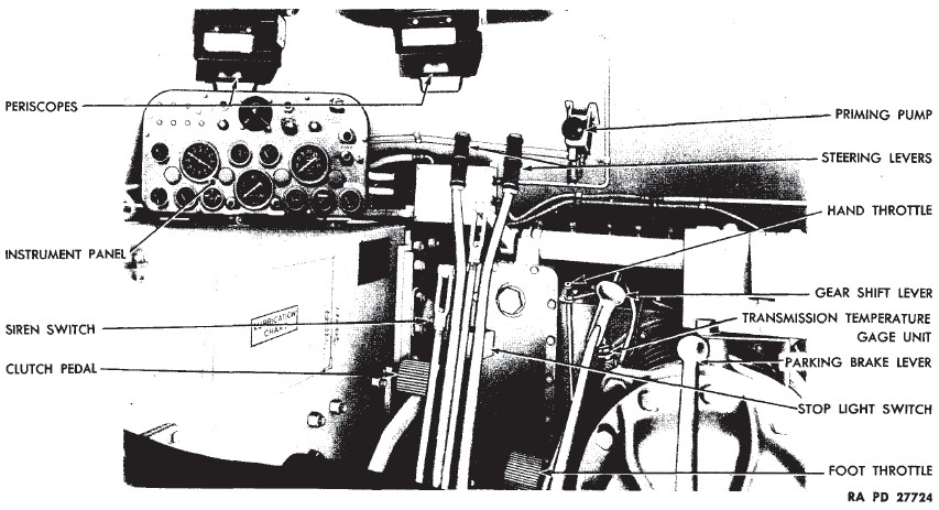
The driver's station is shown in this picture. Since the M10A1 had a single engine, the clutch lockouts found on the M10 were absent. (Picture from TM 9-731G 3-inch Gun Motor Carriage M10A1.)
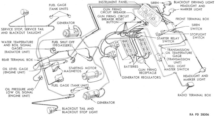
The electrical system is diagrammed here. Two 12-volt storage batteries were connected in series on the left side of the hull floor in the fighting compartment, forming a 24-volt system. (Picture from TM 9-1750L Hull and Turret Electrical Systems, Tracks and Suspension for 3-inch Gun Motor Carriages M10 and M10A1.)
