Smoke Generator Carrier M1059.
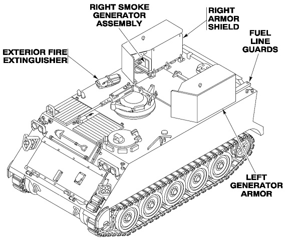
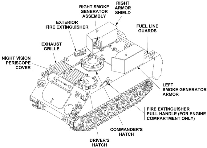
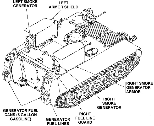
The arrangement of the smoke generator assemblies and roof stowage can be seen here. (Picture from TM 9-2350-261-10.)
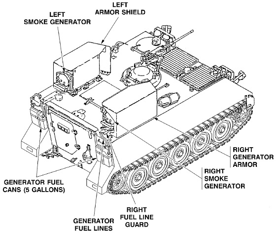
The smoke generators were fueled by cans on the rear of the vehicle. Note that the generators were not directly across from one another on the vehicle's roof. (Picture from TM 9-2350-261-10.)
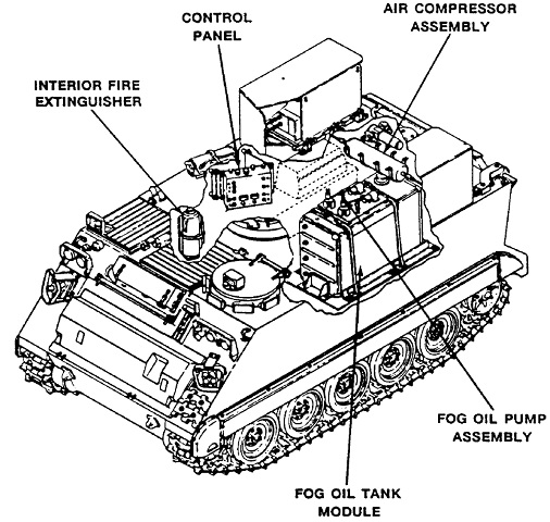
The interior arrangement can be seen here. (Picture from TM 9-2350-261-10.)
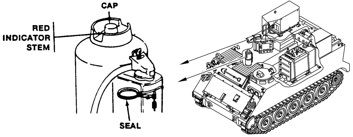
Two portable fire extinguishers were stowed, one on the top deck and the second on the right side of the passenger compartment. If the red indicator stem was extended, the extinguisher needed to be replaced. (Picture from TM 9-2350-261-10.)
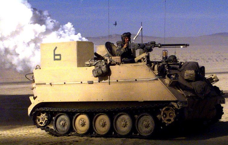
The two M54 smoke generators on the roof of this M1059 are doing their part to obscure the battlefield. The yellow strobe light and sensors on the vehicle's side are part of its MILES combat simulation equipment. (Picture take 19 Mar 1997 by SSgt. William Cronk; available from the Defense Visual Information Center.)
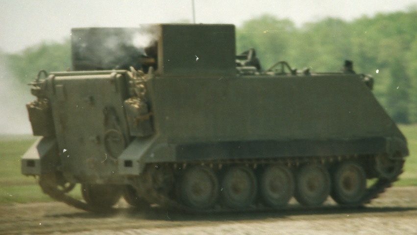
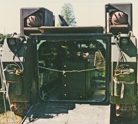
Details of rear stowage and the locations of the smoke generators can be seen here. The fuel cans stowed on each side of the rear ramp were for operating the generators. (Photo by Richard S. Eshleman.)
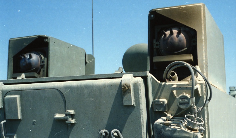
The smoke generator outlets are displayed in this image. Note the fuel lines leading from the stowed cans to the generators. (Photo by Richard S. Eshleman.)
The RISE-enhanced vehicle is shown here. (Picture from TM 9-2350-277-10.)
Note that the smoke generator fuel cans have been mounted on the external fuel tanks. (Picture from TM 9-2350-277-10.)
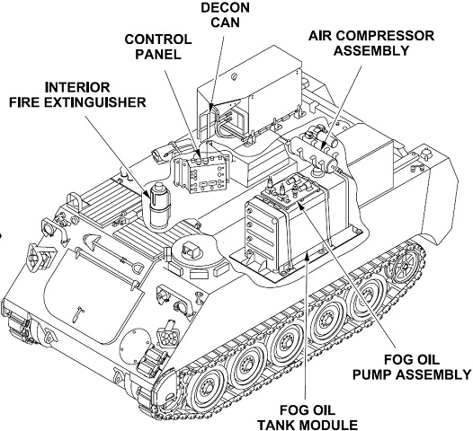
Internal arrangements are sketched here. (Picture from TM 9-2350-277-10.)
With the rear ramp lowered, the fog oil tank module dominates the passenger compartment, and the silver air compressor can be seen attached to the ceiling just inside the ramp opening. (Photo by Richard S. Eshleman.)
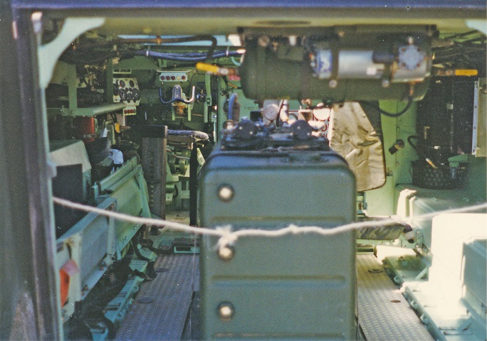
A closer view provides more detail of the air compressor and fog oil pump assemblies, and the driver's steering yoke can be seen to the front left. (Photo by Richard S. Eshleman.)
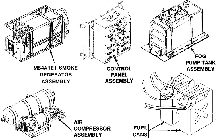
The different components of the smoke generator system M157A2 are drawn in this image. (Picture from TM 9-2350-277-10.)
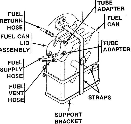
Details of the smoke generator fuel can fittings are sketched here. (Picture from TM 9-2350-277-10.)
